EP0703523A1 - Palm rest for a data processing apparatus keyboard - Google Patents
Palm rest for a data processing apparatus keyboard Download PDFInfo
- Publication number
- EP0703523A1 EP0703523A1 EP95306715A EP95306715A EP0703523A1 EP 0703523 A1 EP0703523 A1 EP 0703523A1 EP 95306715 A EP95306715 A EP 95306715A EP 95306715 A EP95306715 A EP 95306715A EP 0703523 A1 EP0703523 A1 EP 0703523A1
- Authority
- EP
- European Patent Office
- Prior art keywords
- palm rest
- lid
- keyboard
- data processing
- processing apparatus
- Prior art date
- Legal status (The legal status is an assumption and is not a legal conclusion. Google has not performed a legal analysis and makes no representation as to the accuracy of the status listed.)
- Withdrawn
Links
Images


Classifications
-
- G—PHYSICS
- G06—COMPUTING; CALCULATING OR COUNTING
- G06F—ELECTRIC DIGITAL DATA PROCESSING
- G06F1/00—Details not covered by groups G06F3/00 - G06F13/00 and G06F21/00
- G06F1/16—Constructional details or arrangements
-
- G—PHYSICS
- G06—COMPUTING; CALCULATING OR COUNTING
- G06F—ELECTRIC DIGITAL DATA PROCESSING
- G06F1/00—Details not covered by groups G06F3/00 - G06F13/00 and G06F21/00
- G06F1/16—Constructional details or arrangements
- G06F1/1613—Constructional details or arrangements for portable computers
- G06F1/1615—Constructional details or arrangements for portable computers with several enclosures having relative motions, each enclosure supporting at least one I/O or computing function
- G06F1/1616—Constructional details or arrangements for portable computers with several enclosures having relative motions, each enclosure supporting at least one I/O or computing function with folding flat displays, e.g. laptop computers or notebooks having a clamshell configuration, with body parts pivoting to an open position around an axis parallel to the plane they define in closed position
-
- B—PERFORMING OPERATIONS; TRANSPORTING
- B41—PRINTING; LINING MACHINES; TYPEWRITERS; STAMPS
- B41J—TYPEWRITERS; SELECTIVE PRINTING MECHANISMS, i.e. MECHANISMS PRINTING OTHERWISE THAN FROM A FORME; CORRECTION OF TYPOGRAPHICAL ERRORS
- B41J3/00—Typewriters or selective printing or marking mechanisms characterised by the purpose for which they are constructed
- B41J3/36—Typewriters or selective printing or marking mechanisms characterised by the purpose for which they are constructed for portability, i.e. hand-held printers or laptop printers
-
- G—PHYSICS
- G06—COMPUTING; CALCULATING OR COUNTING
- G06F—ELECTRIC DIGITAL DATA PROCESSING
- G06F1/00—Details not covered by groups G06F3/00 - G06F13/00 and G06F21/00
- G06F1/16—Constructional details or arrangements
- G06F1/1613—Constructional details or arrangements for portable computers
- G06F1/1633—Constructional details or arrangements of portable computers not specific to the type of enclosures covered by groups G06F1/1615 - G06F1/1626
- G06F1/1656—Details related to functional adaptations of the enclosure, e.g. to provide protection against EMI, shock, water, or to host detachable peripherals like a mouse or removable expansions units like PCMCIA cards, or to provide access to internal components for maintenance or to removable storage supports like CDs or DVDs, or to mechanically mount accessories
Definitions
- the present invention relates to a palm rest on which a keyboard operator can rest their palms and by which it is possible to carry the keyboard or to carry a data processing apparatus including the keyboard.
- a palm rest is provided for the keyboard of a data processing apparatus which both facilitates the carrying of the apparatus and improves the key input operation.
- One such palm rest can be stored in a body of a case assembly wherein a keyboard is mounted.
- the type of palm rest that can be stored which is generally called a sliding type, is mounted on a slide mechanism that is provided on a side wall, which extends from the front to the rear of the case assembly (the display side), and both ends of the palm rest are so supported on the slide that it can be extracted from and retracted within the case assembly.
- the slide mechanism of a sliding type palm rest must be formed of a plastic that slides easily, (2) precise manufacturing is required, and (3) the number of parts comprising the palm rest increases, manufacturing costs increase accordingly. Since the slide mechanism must have a predetermined mechanical strength in order to be used as a handle for carrying the data processing apparatus, a slide mechanism can not be provided at the front side of the case assembly (the key operator side) and the palm rest must be lengthened in the direction of the width of the case assembly so that it extends to the area beyond the portion where the palms of a key operator are normally rested (the area beyond the typing key area).
- Required is a simply structured palm rest that can be covered within the lid of a data processing apparatus and that does not have to extend beyond its usable length.
- the present invention provides a palm rest and a data processing apparatus as set out in the attached claims.
- a palm rest is installed into a data processing apparatus and is preferably rotatably hinged on shafts at a case assembly.
- the palm rest is capable of holding an operator's palms when rotated outward; is covered with the lid when the lid is closed; and forms a handle when rotated outward and the lid is closed.
- the surface of a palm rest, on which surface the palms of an operator are to be rested, is preferably in the same plane as that formed by the keyboard.
- a palm rest according to the invention is preferably hinged on the front of the casing.
- a palm rest according to the invention is preferably held upright and is held in contact with the internal wall of the lid when the palm rest has been rotated inwardly and the lid is closed.
- a casing mounts a keyboard and a lid, and the apparatus further comprises a palm rest rotatably hinged on the casing which is capable of holding an operator's palms when rotated outward, which is storable in the lid when the lid is closed, and which forms a handle when the palm rest is rotated outward and the lid is closed.
- a palm rest is thus preferably rotatably hinged on a case assembly within which a keyboard is mounted.
- the palm rest When the palm rest is rotated outward, the palms of an operator can be rested on it, thus facilitating the key input operation.
- the palm rest When lifted to an upright position, the palm rest can be stored in a lid that covers the keyboard so that it does not project outward from the data processing apparatus and does not enlarge the overall external dimensions of the apparatus.
- a palm rest which is so designed that it can be rotated between its use position and its storage position, can have a simpler mechanism with fewer components than a palm rest that is slid in for storage, and such precise manufacturing is not required. Manufacturing costs can therefore be reduced.
- the palm rest when rotated outward forms a gap between it and the front of the case assembly, a user can slip his fingers into the gap and while holding the palm rest use it as a handle by which to carry the data processing apparatus.
- the surface of the palm rest by which the palms of a key input operator are supported is preferably in the same plane as the surface of the keyboard. An operator can therefore input data while maintaining a natural posture.
- the palm rest is preferably hinged on the front wall of the case assembly. Therefore, it is not necessary to support both ends of the palm rest at the side walls of the case assembly as is conventional. Also, an uneconomical arrangement where a palm rest is lengthened so that it extends beyond the typing key area is not required, and an economical design can be provided.
- the palm rest is preferably held in contact with the internal wall of the lid by closing the lid while the palm rest is upright. The palm rest is therefore held securely when it is stored.
- the palm rest can be tightly stored in the lid.
- the apparatus can be stored in a desk drawer, etc. Further, by extracting the palm rest from the case assembly and using it as a handle, the data processing apparatus can be easily carried.
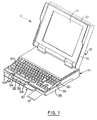
- Fig. 1 is a general perspective view illustrating a PC (personal computer) on which a palm rest is installed according to one embodiment of the present invention.
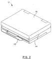
- Fig. 2 is a perspective view illustrating the state when the palm rest is used as a handle according to the embodiment of the present invention.
- Fig. 3 is a perspective view illustrating the state when the palm rest is stored in a lid according to the embodiment of the present invention.
- Fig. 4 is an exploded perspective view illustrating a case assembly to which a palm rest is attached according to the embodiment of the present invention.
- Fig. 5 is a perspective view illustrating the structure of the attachment arrangement for the palm rest according to the embodiment of the present invention.
- Fig. 6 is a cross section showing the attachment arrangement for the palm rest according to the embodiment of the present invention.
- Fig. 7 is a side view showing how the palm rest is used according to the embodiment of the present invention.
- Fig. 8 is a side view showing the pivoting function of the palm rest according to the embodiment of the present invention.
- Fig. 9 is a partial cross section showing the state when the palm rest is stored in the lid according to the embodiment of the present invention.
- Figs. 1 through 3 illustrate a PC (Personal Computer) 12 to which a palm rest 10 is attached according to one embodiment of the present invention.
- PC Personal Computer
- the PC 12 includes a rectangular case assembly 14 and a lid 18, which has a display 16 and which is so hinged on the case assembly 14 that it can be opened and closed.
- the case assembly 14 includes an upper case 20 and a lower case 22, as is shown in Fig. 4.
- Various packages and a battery that constitute the PC 12 are to be mounted on a base plate 22A of the lower case 22.
- Angle members 24 are located around the periphery of the base plate 22A. The angle members 24 engage the bottom ends of a front wall 26 and side walls 28, which are formed by folding the peripheral portions of the upper case 20 downward, so that a hollow storage portion is defined between the upper case 20 and the lower case 22.
- the side walls 28 of the upper case 20 have two levels, one runs from the center toward the rear and the other, which is lower, runs from the center toward the front.
- a slope 30 is formed at the center of the side walls 28 to communicate with those two levels.
- the upper edge of the thus structured side wall 28 contacts a circumferential wall 31 of the lid 18 when the lid 14 is closed.
- An auxiliary frame 32 which has a U-shaped form in Fig. 9, is provided at the free end of the circumferential wall 31.
- the lower edge of the auxiliary frame 32 abuts upon the lower levels of the side walls 28 and upon the slopes 30, so that between the lid 18 and a keyboard 34 is formed the storage space wherein the palm rest 10, which will be described later, is stored at the side that faces an operator (see Fig. 8).
- Inclined support plates 36 are installed from the midline of the upper case 20 to the front. To cover gaps that appear due to the inclination, a triangular plate 38 is provided at the inside of each side wall 28. As the keyboard 34 is attached to the inclined support plates 36, the keyboard 34 is inclined toward an operator to facilitate key input manipulation.
- slits 40 are formed on the front side of the base board 22A of the lower case 22, and shaft receiving members 42 that have openings at the top respectively are arranged at a predetermined interval.
- Each of the upper edges of each leg plate 44 of the shaft receiving members 42 is notched to form a semicircular shaft receiving groove 46.
- Ribs 48 and 50 are projected from the base board 22A on both sides of each of the slits 40 to ensure the rigidity of the shaft receiving members 42.
- the palm rest 10 a long plate, is so designed that when it is rotated forward, a support face 10A is formed that has the same inclination angle as that of the keyboard 34 (see Fig. 7).
- the center portion of the palm rest 10 is notched to form a rectangular handhold 52 that a user grasps.
- plate arms 54 extend in a direction that is perpendicular to the palm rest 10.
- Shaft pins 56 are integrally formed at the end of each arm 54 and project outward from both sides of the arms 54.
- the arms 54 are inserted into the shaft receiving members 42 through the slits 40, as is shown in Fig. 5, the arms 54 are supported by the shaft receiving grooves 46, which are formed in the leg plates 44.
- bottom faces 54A of the arms 54 abut upon the angle member 24 to restrict the rotation of the palm rest 54, and the support face 10A is so positioned that it becomes an extension of the surface of the keyboard 34.
- the palm rest 10 is so designed and sized that when it is upright, a rear face 10B contacts the top surface of the keyboard 34, the bottom face 10C abuts upon the internal wall of the auxiliary frame 32 of the lid 18, and the palm rest 10 is securely held.
- vertical slits 58 are formed in the front wall 26 of the upper case 20 at positions that correspond to those of the slits 40 in the shaft receiving members 42.
- Horizontal slits 62 are formed in pressure plates 60, which extend inward horizontally from the front wall 26, and communicate with the respective vertical slits 58.
- slits 64 (see Fig. 1) that correspond to the horizontal slits 62 are also formed in the operator side of the keyboard 34.
- the shaft pins 56 that are supported by the respective shaft receiving grooves 46 are pressed down by the pressure plates 60. Further, the vertical slits 58, the horizontal slits 62, and the slits 64 permit the palm rest 10 to be pivoted from the reclined state to the upright state at the shaft receiving pins 56.
- bosses 66 that are open at both ends are provided on the base board 22A of the lower case 22.
- Screws 68 are inserted from the bottom of the base board 22A and engage respective internal threads 70 provided on the upper case 20 to partially secure the upper and lower cases 20 and 22.
- the palm rest 10 is hinged on the front wall 26 of the case assembly 14, it is not necessary for both ends of the palm rest to be supported by using the side walls of the case assembly as done conventionally, and it is also not necessary to extend the palm rest into an area M that lies beyond the typing key area.
- the lid 18 is closed while the palm rest 10 is in the reclined position, as is shown Fig. 2.
- the palm rest 10 can then serve as a handle. A user may slip his fingers under the handhold 52 and while holding it carry the PC 12.
- the palm rest 10 is rotated toward the shaft pin 56 until it is upright. Then, when the rear face 10B of the palm rest 10 contacts the top face of the keyboard 34 the rotation is stopped.
- the internal wall of the auxiliary frame 32 contacts the bottom face 10C of the palm rest 10 and the palm rest 10 is held securely.
- the present invention with the above described arrangement can be employed as a palm rest and as a handle for carrying a data processing apparatus. Since the palm rest is so designed that by being pivoted upward it can be securely stored within the lid of a data processing apparatus, it will not project outward from the data processing apparatus, and will not expand the footprint of the apparatus. In addition, because of the employment of a palm rest that can be rotated, the structure of the apparatus is simple. Further, as the palm rest is hinged on the front wall of the case assembly of a data processing apparatus, the palm rest does not have to be lengthened more than is necessary for its use as a typing aid.
Applications Claiming Priority (2)
| Application Number | Priority Date | Filing Date | Title |
|---|---|---|---|
| JP228295/94 | 1994-09-22 | ||
| JP6228295A JPH0895690A (ja) | 1994-09-22 | 1994-09-22 | パームレスト及びこれを備えた情報処理装置 |
Publications (1)
| Publication Number | Publication Date |
|---|---|
| EP0703523A1 true EP0703523A1 (en) | 1996-03-27 |
Family
ID=16874231
Family Applications (1)
| Application Number | Title | Priority Date | Filing Date |
|---|---|---|---|
| EP95306715A Withdrawn EP0703523A1 (en) | 1994-09-22 | 1995-09-22 | Palm rest for a data processing apparatus keyboard |
Country Status (5)
| Country | Link |
|---|---|
| US (1) | US5596482A (ja) |
| EP (1) | EP0703523A1 (ja) |
| JP (1) | JPH0895690A (ja) |
| KR (1) | KR960011619A (ja) |
| CN (1) | CN1085355C (ja) |
Cited By (1)
| Publication number | Priority date | Publication date | Assignee | Title |
|---|---|---|---|---|
| EP1452947A1 (en) * | 2003-02-24 | 2004-09-01 | Kabushiki Kaisha Toshiba | Electronic apparatus having a latch to hold two units in a closed position and to be operated for release |
Families Citing this family (38)
| Publication number | Priority date | Publication date | Assignee | Title |
|---|---|---|---|---|
| US5860015A (en) * | 1995-12-14 | 1999-01-12 | Gateway 2000, Inc. | Detachable palm rest with backup battery |
| US5835344A (en) * | 1996-09-18 | 1998-11-10 | Compaq Computer Corporation | Portable computer system with integral carrying case |
| JPH10154023A (ja) | 1996-11-22 | 1998-06-09 | Fujitsu Ltd | 携帯情報処理装置 |
| US5971148A (en) * | 1997-01-27 | 1999-10-26 | Jackson; W. Shaun | Luggage for nomadic computing |
| US7103380B1 (en) * | 1997-04-04 | 2006-09-05 | Ditzik Richard J | Wireless handset communication system |
| TW339853U (en) * | 1997-07-15 | 1998-09-01 | Inventec Corp | A closing position element for notebook computer display with a wrist rest |
| US6008983A (en) * | 1997-07-29 | 1999-12-28 | Yen; Jung-Chuan | Adjusting device for a screen of a computer |
| US6269948B1 (en) | 1998-01-26 | 2001-08-07 | W. Shaun Jackson | Luggage for nomadic computing |
| US6262716B1 (en) * | 1998-07-01 | 2001-07-17 | Gateway, Inc. | Information processing apparatus having a numeric keypad with cover that functions as a palm rest |
| US6195255B1 (en) * | 1998-10-03 | 2001-02-27 | Stanley A. Kim | Notebook computer and wrist support |
| US6619597B1 (en) * | 1999-02-11 | 2003-09-16 | Robert J. Sheppard | Keyboard wrist support |
| US6012788A (en) * | 1999-04-30 | 2000-01-11 | Haworth, Inc. | Laptop computer desk |
| US6385037B2 (en) | 1999-05-19 | 2002-05-07 | Dell Products L.P. | User configured palm rests for a portable computer system |
| US6560726B1 (en) | 1999-08-19 | 2003-05-06 | Dell Usa, L.P. | Method and system for automated technical support for computers |
| US6606716B1 (en) | 1999-10-06 | 2003-08-12 | Dell Usa, L.P. | Method and system for automated technical support for computers |
| US6760708B1 (en) | 1999-08-19 | 2004-07-06 | Dell Products L.P. | Method and system for migrating stored data to a build-to-order computing system |
| US6556431B1 (en) | 1999-10-06 | 2003-04-29 | Dell Usa, L.P. | System and method for converting alternating current into direct current |
| US6539499B1 (en) | 1999-10-06 | 2003-03-25 | Dell Usa, L.P. | Graphical interface, method, and system for the provision of diagnostic and support services in a computer system |
| US6564220B1 (en) | 1999-10-06 | 2003-05-13 | Dell Usa, L.P. | System and method for monitoring support activity |
| US6317316B1 (en) | 1999-10-06 | 2001-11-13 | Dell Usa, L.P. | Method and system for integrated personal computer components |
| US6563698B1 (en) | 1999-10-06 | 2003-05-13 | Dell Usa, L.P. | System and method for providing a computer system with a detachable component |
| US6598223B1 (en) | 1999-10-06 | 2003-07-22 | Dell Usa, L.P. | Method and system for installing and testing build-to-order components in a defined configuration computer system |
| US6574615B1 (en) | 1999-10-06 | 2003-06-03 | Dell Usa, L.P. | System and method for monitoring support activity |
| US6442018B1 (en) * | 1999-12-01 | 2002-08-27 | International Business Machine Corporation | Briefcase computer |
| USD432538S (en) * | 1999-12-29 | 2000-10-24 | Intel Corporation | Keyboard |
| IL135717A0 (en) * | 2000-04-18 | 2001-05-20 | Wagner Issac | Forearm rest positioning the hands above a computer keyboard or other interface |
| US6462937B1 (en) | 2000-09-22 | 2002-10-08 | Dell Products L.P. | Computer having an integrated gaming control pad |
| JP3992455B2 (ja) * | 2001-06-04 | 2007-10-17 | ジーイー・メディカル・システムズ・グローバル・テクノロジー・カンパニー・エルエルシー | 超音波診断装置 |
| TWI269959B (en) * | 2001-08-03 | 2007-01-01 | Darfon Electronics Corp | Input device |
| US6618242B2 (en) | 2001-09-21 | 2003-09-09 | Dell Products L.P. | Method for retaining a user configurable wrist pad |
| US6654230B1 (en) | 2002-05-02 | 2003-11-25 | International Business Machines Corp. | Rotational wrist pad operably linked to extendable legs of a computer having a backside surface configured for flush storage of the wrist pad |
| US10671125B2 (en) | 2002-06-14 | 2020-06-02 | Benjamin J. Kwitek | Hand pads for tablet type computers |
| TWM255987U (en) * | 2004-01-05 | 2005-01-21 | Action Electronics Co Ltd | LCD display handle for DVD player |
| US7508662B2 (en) * | 2006-04-05 | 2009-03-24 | Apple Inc. | Handle arrangement with integrated heat pipe |
| WO2011093853A1 (en) | 2010-01-26 | 2011-08-04 | Hewlett-Packard Development Company, L.P. | Handle attachment |
| EP3540558B1 (en) * | 2010-10-18 | 2020-09-23 | Apple Inc. | Portable computer with touch pad |
| TWI502311B (zh) * | 2012-01-06 | 2015-10-01 | Wistron Corp | 可攜式電子裝置之擴充裝置 |
| JP2017185756A (ja) * | 2016-04-08 | 2017-10-12 | セイコーエプソン株式会社 | テープ印刷装置 |
Citations (3)
| Publication number | Priority date | Publication date | Assignee | Title |
|---|---|---|---|---|
| JPS6094377A (ja) * | 1983-10-31 | 1985-05-27 | Canon Inc | キヤリングケ−ス |
| JPS61213911A (ja) * | 1985-03-19 | 1986-09-22 | Canon Inc | 電子機器 |
| JPH02244210A (ja) * | 1989-03-17 | 1990-09-28 | Hitachi Ltd | 携帯形電子機器 |
Family Cites Families (5)
| Publication number | Priority date | Publication date | Assignee | Title |
|---|---|---|---|---|
| JPS5650037A (en) * | 1979-09-28 | 1981-05-07 | Hitachi Ltd | Electromagnetic focusing type colour picture tube |
| US5011198A (en) * | 1989-04-20 | 1991-04-30 | Apple Computer, Inc. | Handle latch assembly |
| JP3097065B2 (ja) * | 1991-04-23 | 2000-10-10 | セイコーエプソン株式会社 | 情報処理機器 |
| US5247285A (en) * | 1992-03-06 | 1993-09-21 | Everex Systems, Inc. | Standup portable personal computer with detachable wireless keyboard and adjustable display |
| JPH05342164A (ja) * | 1992-05-21 | 1993-12-24 | Internatl Business Mach Corp <Ibm> | 印刷機能付情報処理システム |
-
1994
- 1994-09-22 JP JP6228295A patent/JPH0895690A/ja active Pending
-
1995
- 1995-07-13 CN CN95107561A patent/CN1085355C/zh not_active Expired - Fee Related
- 1995-09-19 KR KR1019950031274A patent/KR960011619A/ko active IP Right Grant
- 1995-09-22 EP EP95306715A patent/EP0703523A1/en not_active Withdrawn
- 1995-09-22 US US08/532,345 patent/US5596482A/en not_active Expired - Fee Related
Patent Citations (3)
| Publication number | Priority date | Publication date | Assignee | Title |
|---|---|---|---|---|
| JPS6094377A (ja) * | 1983-10-31 | 1985-05-27 | Canon Inc | キヤリングケ−ス |
| JPS61213911A (ja) * | 1985-03-19 | 1986-09-22 | Canon Inc | 電子機器 |
| JPH02244210A (ja) * | 1989-03-17 | 1990-09-28 | Hitachi Ltd | 携帯形電子機器 |
Non-Patent Citations (3)
| Title |
|---|
| PATENT ABSTRACTS OF JAPAN vol. 11, no. 45 (P - 546) 10 February 1987 (1987-02-10) * |
| PATENT ABSTRACTS OF JAPAN vol. 14, no. 569 (P - 1144) 18 December 1990 (1990-12-18) * |
| PATENT ABSTRACTS OF JAPAN vol. 9, no. 242 (M - 417) 28 September 1985 (1985-09-28) * |
Cited By (2)
| Publication number | Priority date | Publication date | Assignee | Title |
|---|---|---|---|---|
| EP1452947A1 (en) * | 2003-02-24 | 2004-09-01 | Kabushiki Kaisha Toshiba | Electronic apparatus having a latch to hold two units in a closed position and to be operated for release |
| US7274562B2 (en) | 2003-02-24 | 2007-09-25 | Kabushiki Kaisha Toshiba | Electronic apparatus having a latch to hold two units in a closed position and to be operated for release |
Also Published As
| Publication number | Publication date |
|---|---|
| KR960011619A (ko) | 1996-04-20 |
| CN1085355C (zh) | 2002-05-22 |
| US5596482A (en) | 1997-01-21 |
| JPH0895690A (ja) | 1996-04-12 |
| CN1119295A (zh) | 1996-03-27 |
Similar Documents
| Publication | Publication Date | Title |
|---|---|---|
| EP0703523A1 (en) | Palm rest for a data processing apparatus keyboard | |
| US5107402A (en) | Portable computer provided with a tilting screen articulated thereon by tilting linkage with a bent shape | |
| US5490036A (en) | Portable computer with tiltable keyboard structure having releasably engageable latch assembly members extending therefrom | |
| US5646817A (en) | Adjustable keyboard | |
| US5260884A (en) | Brief case having integral computer | |
| US5445266A (en) | Carrying case and variable-angle support stand for portable computer | |
| JP3701097B2 (ja) | 開閉可能なカバーを有する機器 | |
| US20020163778A1 (en) | Protective case and keyboard system for a handheld computer | |
| EP0254889A2 (en) | Portable electronic apparatus | |
| JPH1091281A (ja) | 情報処理機器 | |
| JPH07219682A (ja) | ノートブック型パソコン及びバッテリーケース | |
| CA2131589A1 (en) | Combined notepad and notebook computer | |
| US4882684A (en) | Engaging device of a keyboard for a data processing unit | |
| JPH09206118A (ja) | 携帯情報機器用キャリングケース | |
| JP3924840B2 (ja) | 情報処理装置 | |
| JP2923389B2 (ja) | 手書き入力可能なハンドヘルド・コンピュータ装置 | |
| JPH02112010A (ja) | 電子機器 | |
| JPH0445053Y2 (ja) | ||
| JP2002108505A (ja) | 情報処理装置 | |
| JPH09244763A (ja) | 電子機器 | |
| JPH0822350A (ja) | キーボード面のチルト機構 | |
| JPS6234342Y2 (ja) | ||
| JPH07182068A (ja) | 情報処理装置 | |
| KR0131711Y1 (ko) | 노트북 컴퓨터의 키보드장치 | |
| JPH0793051A (ja) | 携帯型電子機器の収納ケース |
Legal Events
| Date | Code | Title | Description |
|---|---|---|---|
| PUAI | Public reference made under article 153(3) epc to a published international application that has entered the european phase |
Free format text: ORIGINAL CODE: 0009012 |
|
| AK | Designated contracting states |
Kind code of ref document: A1 Designated state(s): DE FR GB |
|
| STAA | Information on the status of an ep patent application or granted ep patent |
Free format text: STATUS: THE APPLICATION IS DEEMED TO BE WITHDRAWN |
|
| 18D | Application deemed to be withdrawn |
Effective date: 19960928 |