EP0700575B1 - Tete de bobine - Google Patents
Tete de bobine Download PDFInfo
- Publication number
- EP0700575B1 EP0700575B1 EP94911841A EP94911841A EP0700575B1 EP 0700575 B1 EP0700575 B1 EP 0700575B1 EP 94911841 A EP94911841 A EP 94911841A EP 94911841 A EP94911841 A EP 94911841A EP 0700575 B1 EP0700575 B1 EP 0700575B1
- Authority
- EP
- European Patent Office
- Prior art keywords
- wire
- winding
- connection
- tool head
- connecting device
- Prior art date
- Legal status (The legal status is an assumption and is not a legal conclusion. Google has not performed a legal analysis and makes no representation as to the accuracy of the status listed.)
- Expired - Lifetime
Links
Images

Classifications
-
- H—ELECTRICITY
- H01—ELECTRIC ELEMENTS
- H01F—MAGNETS; INDUCTANCES; TRANSFORMERS; SELECTION OF MATERIALS FOR THEIR MAGNETIC PROPERTIES
- H01F41/00—Apparatus or processes specially adapted for manufacturing or assembling magnets, inductances or transformers; Apparatus or processes specially adapted for manufacturing materials characterised by their magnetic properties
- H01F41/02—Apparatus or processes specially adapted for manufacturing or assembling magnets, inductances or transformers; Apparatus or processes specially adapted for manufacturing materials characterised by their magnetic properties for manufacturing cores, coils, or magnets
- H01F41/04—Apparatus or processes specially adapted for manufacturing or assembling magnets, inductances or transformers; Apparatus or processes specially adapted for manufacturing materials characterised by their magnetic properties for manufacturing cores, coils, or magnets for manufacturing coils
- H01F41/10—Connecting leads to windings
-
- H—ELECTRICITY
- H01—ELECTRIC ELEMENTS
- H01F—MAGNETS; INDUCTANCES; TRANSFORMERS; SELECTION OF MATERIALS FOR THEIR MAGNETIC PROPERTIES
- H01F41/00—Apparatus or processes specially adapted for manufacturing or assembling magnets, inductances or transformers; Apparatus or processes specially adapted for manufacturing materials characterised by their magnetic properties
- H01F41/02—Apparatus or processes specially adapted for manufacturing or assembling magnets, inductances or transformers; Apparatus or processes specially adapted for manufacturing materials characterised by their magnetic properties for manufacturing cores, coils, or magnets
- H01F41/04—Apparatus or processes specially adapted for manufacturing or assembling magnets, inductances or transformers; Apparatus or processes specially adapted for manufacturing materials characterised by their magnetic properties for manufacturing cores, coils, or magnets for manufacturing coils
- H01F41/06—Coil winding
- H01F41/076—Forming taps or terminals while winding, e.g. by wrapping or soldering the wire onto pins, or by directly forming terminals from the wire
-
- Y—GENERAL TAGGING OF NEW TECHNOLOGICAL DEVELOPMENTS; GENERAL TAGGING OF CROSS-SECTIONAL TECHNOLOGIES SPANNING OVER SEVERAL SECTIONS OF THE IPC; TECHNICAL SUBJECTS COVERED BY FORMER USPC CROSS-REFERENCE ART COLLECTIONS [XRACs] AND DIGESTS
- Y10—TECHNICAL SUBJECTS COVERED BY FORMER USPC
- Y10T—TECHNICAL SUBJECTS COVERED BY FORMER US CLASSIFICATION
- Y10T29/00—Metal working
- Y10T29/49—Method of mechanical manufacture
- Y10T29/49002—Electrical device making
- Y10T29/4902—Electromagnet, transformer or inductor
- Y10T29/49071—Electromagnet, transformer or inductor by winding or coiling
-
- Y—GENERAL TAGGING OF NEW TECHNOLOGICAL DEVELOPMENTS; GENERAL TAGGING OF CROSS-SECTIONAL TECHNOLOGIES SPANNING OVER SEVERAL SECTIONS OF THE IPC; TECHNICAL SUBJECTS COVERED BY FORMER USPC CROSS-REFERENCE ART COLLECTIONS [XRACs] AND DIGESTS
- Y10—TECHNICAL SUBJECTS COVERED BY FORMER USPC
- Y10T—TECHNICAL SUBJECTS COVERED BY FORMER US CLASSIFICATION
- Y10T29/00—Metal working
- Y10T29/51—Plural diverse manufacturing apparatus including means for metal shaping or assembling
- Y10T29/5136—Separate tool stations for selective or successive operation on work
- Y10T29/5137—Separate tool stations for selective or successive operation on work including assembling or disassembling station
- Y10T29/5141—Separate tool stations for selective or successive operation on work including assembling or disassembling station and means to stake electric wire to commutator or armature in assembling of electric motor or generator
-
- Y—GENERAL TAGGING OF NEW TECHNOLOGICAL DEVELOPMENTS; GENERAL TAGGING OF CROSS-SECTIONAL TECHNOLOGIES SPANNING OVER SEVERAL SECTIONS OF THE IPC; TECHNICAL SUBJECTS COVERED BY FORMER USPC CROSS-REFERENCE ART COLLECTIONS [XRACs] AND DIGESTS
- Y10—TECHNICAL SUBJECTS COVERED BY FORMER USPC
- Y10T—TECHNICAL SUBJECTS COVERED BY FORMER US CLASSIFICATION
- Y10T29/00—Metal working
- Y10T29/51—Plural diverse manufacturing apparatus including means for metal shaping or assembling
- Y10T29/5147—Plural diverse manufacturing apparatus including means for metal shaping or assembling including composite tool
- Y10T29/5148—Plural diverse manufacturing apparatus including means for metal shaping or assembling including composite tool including severing means
-
- Y—GENERAL TAGGING OF NEW TECHNOLOGICAL DEVELOPMENTS; GENERAL TAGGING OF CROSS-SECTIONAL TECHNOLOGIES SPANNING OVER SEVERAL SECTIONS OF THE IPC; TECHNICAL SUBJECTS COVERED BY FORMER USPC CROSS-REFERENCE ART COLLECTIONS [XRACs] AND DIGESTS
- Y10—TECHNICAL SUBJECTS COVERED BY FORMER USPC
- Y10T—TECHNICAL SUBJECTS COVERED BY FORMER US CLASSIFICATION
- Y10T29/00—Metal working
- Y10T29/51—Plural diverse manufacturing apparatus including means for metal shaping or assembling
- Y10T29/5187—Wire working
Definitions
- the present invention relates to a device for producing a coil winding from winding wire on a winding support with a winding head having a wire guide device and movable relative to the winding support. Furthermore, the invention relates to a method which can be carried out by means of this device for producing an electrically conductive connection.
- Devices of the type mentioned above can be used in the manufacture of coil arrangements in which a wire conductor is wound around the winding support by means of a winding head to form a coil winding and wire ends of the winding wire are connected to connection surfaces of the winding support or those of adjacent components.
- other devices namely a connecting device and a wire separating device, are required in addition to the winding head.
- the procedure can be such that first a wire end is connected to a connecting surface by means of the connecting device, then the actual coil winding is formed around the winding support by means of the winding head, and finally the running wire end of the winding wire is carried out by means of the connecting device is connected to a further connection surface and is severed by means of the wire cutting device.
- the present invention has for its object to provide a generic device or a method that enables the most compact possible construction and a reduction in manufacturing times.
- the wire guide device, the connecting device and the wire separating device are integral devices of the winding head.
- Such a device virtually creates a highly integrated winding head which, in addition to the actual wire guiding function when winding a wire conductor on a winding support, also simultaneously performs the functions of connecting the wire ends to the winding support or a separate connection surface support separate therefrom and the final wire cutting function.
- Due to the combination in a structural unit the entire device is a compact arrangement, so that both in one and the same relative position with respect to the connection surface of the connection surface carrier Connection of the wire conductor to the pad as well as cutting the wire conductor can be done.
- there are no intermediate routes during the establishment of the connection which arise from the fact that, in devices according to the prior art, the wire guide device must be guided from a connecting device to a separating device.
- the device according to the invention is particularly suitable for producing coil arrangements, that is to say both for carrying out a winding process and for carrying out the connection technology
- the device according to the invention can equally advantageously be used in general where it matters, at certain points To create connections between a wire conductor and a connection surface and to guide the wire conductor in the intermediate area with the winding / connecting device according to the invention, referred to here as the winding head, on a predetermined movement path from one connection point to the other connection point.
- a winding process does not have to be carried out in every case, but also with a corresponding axis control of the winding / connecting device, a meandering course in one plane or any other wire course between two connection points can be generated.
- the wire guide device, the connecting device and the wire separating device are combined in one tool head, the actuating or delivery elements necessary for the individual devices being arranged outside the tool head.
- This structure means a miniaturization which enables the use of the device according to the invention even with the smallest connection areas, such as the connection areas of a chip which are only 100 micrometers x 100 micrometers as standard.
- a wire deflection device is preferably assigned to the wire guide device, which enables a wire conductor which is supplied approximately parallel to the connecting device to be deflected transversely to the feed axis of the connecting device so that the wire conductor comes to rest between the connecting device and the connecting surface when the connection is made.
- connection device is not limited to a particular type, but rather that any of the range of connection devices available, such as a thermode, a thermosonic connection device, a laser welding device etc., or a combination thereof , can be selected.
- a laser welding device such a device, as described in DE-OS 42 00 492
- a laser welding device has proven to be advantageous, in which the laser power emitted by a laser source is conducted directly to the connection point by means of a glass fiber conductor.
- the winding head itself does not have to be loaded by the device device forming the laser source, but can be arranged in a stationary manner from the winding head.
- the fiber optic cable can then be used as a connecting device be integrated into the winding head. This makes it possible to use a high-performance laser welding device in the device according to the invention without disadvantageously increasing its mass due to the device device mentioned above.
- the wire guide device can be combined with the connecting device, for example in the case of a thermosonic bonding head as the connecting device, the wire is fed through a capillary in the bonding head.
- the separating device in a functional unit which is then composed of a wire guide device, connecting device and wire separating device.
- An example of this would be a thermosonic bonding head provided with a wire guide capillary, which also has a separating edge formed in the wire contact area. This would allow a high level of integration to be achieved.
- the wire deflection device is preferably formed from a suction device acting transversely to the feed axis of the wire guide device.
- a suction air connection is required in the area of the connecting device for its implementation, which causes the wire conductor fed through the wire guide device approximately parallel to the feed axis of the connecting device to be deflected transversely to the feed axis of the connecting device as a result of the suction force, so that the connecting device can act on the wire conductor, for example by applying heat and pressure in the case of a thermode.
- Another possibility is to provide a gripping device which can be pivoted transversely to the feed axis of the connecting device for the wire deflection device.
- a possible embodiment of a wire deflection device which is similar in principle, but still preferable in terms of the achievable compactness, consists in making the wire guide device itself pivotable transversely to the feed axis of the connecting device, in order then to cooperate with the connection surface of the connection surface carrier which the wire conductor strikes, to cause such a deflection of the wire conductor that the wire conductor comes to rest between the connecting device and the connection surface.
- the device according to the invention is constructed in such a way that the actuating or feed elements assigned to the individual devices are arranged in a tool head carrier which can be coupled to the tool head.
- a connecting device of a certain type For example, the thermocompression method for a connection on a connection surface of a Kapton film and for a chip connection surface have been found the Thermosonic process as advantageous, and a combination of these processes is also conceivable.
- the connecting device however, one and the same actuating or delivery element can always be used. Apart from a simple and quick tool head change, this has a favorable effect on the tool preparation costs.
- actuating or delivery elements There are various options for executing the actuating or delivery elements. For example, they can be designed as compressed air actuators, such as piston / cylinder units, or as solenoid actuators.
- This further wire guide device can be integrated in the connecting device.
- a further advantageous measure for example to establish or increase the connection compatibility between the wire conductor material and the pad material, can consist in providing a protective gas supply device in the area of the connection device.
- Another possible alternative is to provide a vacuum device in the area of the connecting device, for example by surrounding the entire tool head with a vacuum bell.
- the protective gas supply device can also be assigned a coating device which enables an application of a protective layer to the connection point, for example the application of a passivation layer as corrosion protection, preferably while the protective gas is being applied to the connection point.
- a camera in particular a CCD camera equipped with CCD (charge-coupled device) image sensors, which is attached to the tool head itself or also to the tool head carrier can.
- CCD charge-coupled device
- the camera can also be integrated into the tool head or the tool head carrier.
- the device according to one or more of claims 1 to 16 is used to connect a bondable wire conductor directly to the unbumped connection areas of an electronic component, such as a chip.
- the wire is connected directly to the aluminum pads, without bumps having been applied to them beforehand. The consequence of this is a considerable simplification in the electrical connection of chips or components comparable in terms of connection technology.
- a bondable winding wire preferably a copper bonding wire
- connection between the wire and the connection surface takes place in a protective gas atmosphere or under vacuum in order to increase the quality of the connection.
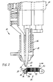
- FIG. 1 shows, in a first embodiment, a winding / connecting device 10 with a tool head carrier 11 and a tool head 12.
- the tool head 12 is detachably connected to the tool head carrier 11 by means of a connecting element 13 designed here as a connecting sleeve 13.
- the connecting sleeve 13 has in its end region facing the tool head carrier 11 an internal thread 14 which interacts with an external thread of the tool head carrier 11, not shown in detail.
- the tool head 12 has a tool holder 15 with tool devices accommodated and guided therein, namely a wire guide device 16, a connecting device 17, a wire separating device 18 and a wire deflecting device 19.
- the devices mentioned are provided at their upper end in FIG. 1 with pneumatic piston / cylinder units 21, 22, 23 provided as feed members .
- Damping devices 25 can be provided between piston rods 24 of the piston / cylinder units 21, 22, 23 and the ends of the devices 16, 17, 18, as exemplified for the wire cutting device 18.
- the devices 16, 17, 18 are not coupled directly to the piston / cylinder units 21, 22, 23 but via the damping devices 25.
- FIG. 1 shows the winding / connecting device 10 in a winding configuration in which the wire guide device 16 is in a position advanced from the tool holder 15.
- a winding wire 26 or generally a wire with which, for example, a wire connection between two connection surfaces is to be created is passed through the tubular wire guide device 16.
- the winding / connecting device 10 can be used in the usual way as a winding head which can be moved in one or more axes in space or generally as a wire guide head.
- the tool head 12 In order to use the winding / connecting device 10 shown in FIG. 1 to connect the wire 26 'to a connecting surface (not shown in FIG. 1) after a winding process or with the free wire end 27 fixed in some other way, the tool head 12 first move in the direction of arrow 28 and the wire guide device 16 is moved into the tool head 12 by actuating the piston / cylinder unit 21. As a result, the wire 26 lies against the underside of the tool head, so that the connecting device 17 can be moved out of the tool head 12 until it lies against the connecting surface with the wire 26 being interposed. Depending on the distance of the tool head 12 from the connection surface, the winding / connecting device 10 as a whole can be advanced in the direction of the feed axis 20.
- connection device 17 this works, for example, with thermocompression or ultrasound excitation with or without simultaneous heating of the connection surface, as a result of which the wire 26 is connected to the connection surface.
- the separating device 18 is extended, which in the exemplary embodiment shown in FIG. 1 has the form of a separating knife in order to cut the wire 26 near the connection point.
- FIG. 2 This configuration of the winding / connection device 10 is shown in FIG. 2 .
- the wire guide device 16 is in the retracted position and the connecting device 17 and the wire separating device 18 are in the advanced position.
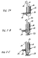
- FIGS. 3 A to 3 C are then still the configurations of the winding / connection device 10 when carrying out a wire connection, such as laying down the wire end to a pad prior to performing a subsequent winding operation or a wire connection between the pads, are described .
- the wire guide device 16, the connecting device 17 and the wire separating device 18 are initially in a completely retracted position and release a channel 30 running transversely to the feed axis 20.
- the wire conductor 26 fed through the wire guide device 16 is brought into a position transverse to the infeed axis 20 by the wire deflection device 19 embodied here as a suction device, with its free wire end Wire feed can be prevented by the wire guide device by means of a clamping device.
- a device can also be provided for threading the wire into the wire guide device in an air-supported manner through nozzle flows.
- the connecting device 17 is extended until it lies against a connecting surface 29 with the interposition of the wire 26. In this position, the wire 26 is now connected to the connecting surface 29.
- the wire cutting device 18 is also extended so that the wire 26 can be separated by the cutting device 18 near the connection point. The severed wire end is then sucked off by the suction device 19.
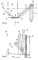
- FIG. 2 shows an example of a possible application of the winding / connecting device 10 according to the invention in its use in the manufacture of a watch coil 31, which is used in electrically operated watches and which has a winding support 32 with a coil winding 33 arranged thereon.
- the connection surfaces of the watch coil 31 are formed by means of a so-called "Kapton film” 34, which consists of a plastic film with metallization layers 35, 36 applied thereon.
- 2 shows two connection points 37, 38 on the metallization layers 35, 36, at which winding wire ends 39, 40 are connected to the metallization layers 35, 36.
- the watch coil 31 shown in FIG. 2 can be produced by means of the winding / connecting device 10 according to the invention by first, as shown in FIGS. 3 A, 3 B, 3 C , a first connection of the winding wire 26 to the first metallization layer 35 below Connection 37 is formed.
- the coil winding 33 is then carried out by superimposing a rotational movement of the winding support 32 about its longitudinal axis and a translational movement of the tool head 12 in the direction of the arrow 41 and finally of the wire 26 performed.
- FIG. 4 shows a tool head 56 with a wire feed device 42 which can be pivoted about an articulation point 43 transversely to the feed axis 20 of the tool head.
- 4 shows the wire guide device 42 both in its winding position oriented essentially parallel to the feed axis 20 and in the pivoted state.
- the pivotability of the wire guide device 42 makes it possible to dispense with a separate deflection device. Rather, in the embodiment shown in FIG. 4 , the winding wire 26 is guided through a wire feed with the wire guide device 42 pivoted onto a connection surface 44 and deflected thereon. In this position, a connecting device 45 which can be advanced in the direction of the infeed axis can be moved up to the connection surface 44, the wire 26 between the connection surface 44 and a contact surface 46 of the connecting device 45 comes to rest.
- the connecting device 45 is designed such that a further wire guiding device 47, for example in the form of a channel, is formed in it in order to guide an additional wire 48 onto the connecting surface 44, so that the connection of the wire 26 with the connection surface 44 can take place simultaneously with the connection of the additional wire 48 to the connection surface 44.
- This additional wire 48 can be designed in such a way that the connection of poorly connectable or connection-incompatible materials of the wire 26 and the connection surface 44 is made possible. It is also possible to match the material of the additional wire 48 to the materials to be connected in such a way that special corrosion protection or insulation from the outside is provided.
- the wire cutting device was not shown in FIG. 4 .
- FIG. 5 shows in a further variant a schematically illustrated tool head 49 which, similar to the tool head 12 shown in FIG. 1 , has a wire guide device 50, a connecting device 51 and a wire separating device 52.
- the tool head 49 has a deflection device 53 which consists of a gripping device which can be pivoted about an articulation point 54 belonging to the tool head 49.
- a deflection device 53 which consists of a gripping device which can be pivoted about an articulation point 54 belonging to the tool head 49.
- the Wire 26 is picked up by a gripper 55 of the deflection device 53 and the held wire 26 with the gripper is pivoted about the articulation point 54 into its left position in FIG. 5 .
- the wire 26 can then be connected to a connecting surface and the wire 26 subsequently cut.
Landscapes
- Engineering & Computer Science (AREA)
- Power Engineering (AREA)
- Manufacturing & Machinery (AREA)
- Wire Processing (AREA)
- Magnetic Heads (AREA)
- Wire Bonding (AREA)
- Adjustment Of The Magnetic Head Position Track Following On Tapes (AREA)
Claims (20)
- Dispositif pour fabriquer un enroulement de bobine en utilisant un fil de bobinage (26) sur un support de bobinage comportant une tête de bobinage (10), qui possède un dispositif guide-fil (16,42,50) et est déplaçable par rapport au support de bobinage, et comportant un dispositif (17,45,51) de réunion du fil servant à établir une liaison électriquement conductrice entre le fil de bobinage et une surface de raccordement d'un support (31) d'une surface de raccordement, et un dispositif (18,52) de sectionnement du fil,
caractérisé en ce
qu'en dehors du dispositif guide-fil (16,42,50) le dispositif (17,45,51) de réunion du fil et le dispositif (18,52) de sectionnement du fil sont prévus sous la forme d'autres dispositifs intégraux de la tête de bobinage (10). - Dispositif selon la revendication 1, caractérisé en ce que le dispositif guide-fil (16,42, 50) dispositif (17,45,51) de réunion du fil et le dispositif (18,52) de sectionnement du fil sont réunis dans une tête d'outil (12,49,56), les organes d'actionnement/d'avance (21,22,23) de ces dispositifs étant situés à l'extérieur de la tête d'outil.
- Dispositif selon la revendication 1 ou 2, caractérisé en ce que le dispositif de réunion (17) est agencé sous la forme d'un conducteur formé d'une fibre de verre, qui est intégré à la tête de bobinage (10) et qui est relié à une source laser disposée de préférence d'une manière indépendante de la tête de bobinage (10).
- Dispositif selon une ou plusieurs des revendications précédentes, caractérisé en ce qu'au dispositif guide-fil (16, 42, 50) est associé un dispositif (19,53) de déviation du fil, qui sert à dévier le fil (26) dans une direction transversale par rapport à l'axe d'avance (20) du dispositif de réunion (17,45,51).
- Dispositif selon une ou plusieurs des revendications précédentes, caractérisé en ce que le dispositif guide-fil (16,42,50) le dispositif de réunion (17,45,51) et le dispositif (18,52) de sectionnement du fil sont réunis en totalité ou en partie pour former une unité fonctionnelle.
- Dispositif selon une ou plusieurs des revendications précédentes, caractérisé en ce que le dispositif (19) de déviation du fil est formé par un dispositif d'aspiration, qui agit transversalement par rapport à l'axe d'avance (20) du dispositif de réunion (17).
- Dispositif selon une ou plusieurs des revendications 1 à 5, caractérisé en ce que le dispositif (53) de déviation du fil est formé par un dispositif de saisie, qui peut basculer transversalement par rapport à l'axe d'avance (20) du dispositif de réunion (51).
- Dispositif selon une ou plusieurs des revendications 1 à 5, caractérisé en ce que pour la déviation du fil, le dispositif guide-fil (42) peut basculer transversalement par rapport à l'axe d'avance (20) du dispositif de réunion (45).
- Dispositif selon une ou plusieurs des revendications précédentes, caractérisé en ce que les organes d'actionnement/d'avance (21,22,23) sont disposés dans un support de tête d'outil (11), qui peut être accouplé à la tête d'outil (12,49,56).
- Dispositif selon une ou plusieurs des revendications précédentes, caractérisé en ce que les organes d'actionnement/d'avance (21,22,23) sont agencés sous la forme d'organes d'actionnement à air comprimé.
- Dispositif selon une ou plusieurs des revendications 1 à 9, caractérisé en ce que les organes d'actionnement/d'avance (21,22,23) sont agencés sous la forme d'organes d'actionnement à électroaimant.
- Dispositif selon une ou plusieurs des revendications précédentes, caractérisé en ce qu'il est prévu un autre dispositif guide-fil (47).
- Dispositif selon la revendication 12, caractérisé en ce que l'autre dispositif guide-fil (47) est intégré dans le dispositif de réunion (45).
- Dispositif selon une ou plusieurs des revendications précédentes, caractérisé en ce qu'un dispositif d'amenée de gaz protecteur est prévu au voisinage du dispositif de réunion (17,45,51).
- Dispositif selon une ou plusieurs des revendications 1 à 13, caractérisé en ce qu'un dispositif à vide servant à produire un vide dans la zone de réunion est prévu au voisinage du dispositif de réunion (17,45,51).
- Dispositif selon une ou plusieurs des revendications précédentes, caractérisé en ce qu'une caméra de contrôle, notamment une caméra à dispositif CCD, c'est-à-dire un dispositif à couplage de charges, est prévue sur la tête d'outil (12,49,56) ou sur le support de tête d'outil (11).
- Procédé pour établir une liaison électriquement conductrice entre un conducteur en forme de fil (26) et une surface de raccordement (29,44) d'un support d'une surface de raccordement à l'aide d'un dispositif selon une ou plusieurs des revendications 1 à 16, caractérisé en ce que le conducteur en forme de fil (26), qui traverse le dispositif guide-fil (16,47,52), est relié directement à une surface de raccordement sans bosse métallisée élevée, utilisée comme contact, (29,44) d'un composant électronique, tel qu'une microplaquette.
- Procédé selon la revendication 17, caractérisé en ce qu'on utilise comme conducteur en forme de fil (26), un fil de bobinage apte à être réuni par soudage, de préférence un fil de liaison en cuivre.
- Procédé selon la revendication 17 ou 18, caractérisé en ce que la liaison du conducteur en forme de fil (26) avec la surface de raccordement (29,44) s'effectue dans une atmosphère de gaz protecteur.
- Procédé selon la revendication 17 ou 18, caractérisé en ce que la liaison du conducteur en forme de fil (26) à la surface de raccordement (29,44) s'effectue sous vide.
Applications Claiming Priority (5)
| Application Number | Priority Date | Filing Date | Title |
|---|---|---|---|
| DE4317897 | 1993-05-28 | ||
| DE4317897 | 1993-05-28 | ||
| DE4325334A DE4325334C2 (de) | 1993-05-28 | 1993-07-28 | Vorrichtung und Verfahren zur Bondverbindung mit einem Wickelkopf |
| DE4325334 | 1993-07-28 | ||
| PCT/DE1994/000395 WO1994028562A1 (fr) | 1993-05-28 | 1994-04-08 | Tete de bobine |
Publications (2)
| Publication Number | Publication Date |
|---|---|
| EP0700575A1 EP0700575A1 (fr) | 1996-03-13 |
| EP0700575B1 true EP0700575B1 (fr) | 1997-01-02 |
Family
ID=25926324
Family Applications (1)
| Application Number | Title | Priority Date | Filing Date |
|---|---|---|---|
| EP94911841A Expired - Lifetime EP0700575B1 (fr) | 1993-05-28 | 1994-04-08 | Tete de bobine |
Country Status (7)
| Country | Link |
|---|---|
| US (1) | US6023837A (fr) |
| EP (1) | EP0700575B1 (fr) |
| JP (1) | JP3190345B2 (fr) |
| AT (1) | ATE147190T1 (fr) |
| DE (1) | DE59401482D1 (fr) |
| ES (1) | ES2096462T3 (fr) |
| WO (1) | WO1994028562A1 (fr) |
Families Citing this family (22)
| Publication number | Priority date | Publication date | Assignee | Title |
|---|---|---|---|---|
| US6233818B1 (en) | 1996-02-12 | 2001-05-22 | David Finn | Method and device for bonding a wire conductor |
| DE19619771A1 (de) * | 1996-02-12 | 1997-08-14 | David Finn | Verfahren und Vorrichtung zur Verlegung eines Drahtleiters auf einem Substrat sowie hiermit hergestellte Substrate |
| US6822195B2 (en) * | 2003-04-02 | 2004-11-23 | General Motors Corporation | Automated weld location system for vehicles |
| JP4363647B2 (ja) | 2004-09-09 | 2009-11-11 | 株式会社小糸製作所 | 車輌用灯具及び車輌用灯具の製造方法 |
| EP2014406A3 (fr) * | 2004-11-02 | 2010-06-02 | HID Global GmbH | Dispositif de pose, dispositif d'établissement de contact, système d'avance, unité de pose et d'établissement de contact, installation de production et ensemble transpondeur |
| WO2007064153A1 (fr) * | 2005-11-29 | 2007-06-07 | Posco | Guide-cable du type a guidage d'air |
| US7971339B2 (en) * | 2006-09-26 | 2011-07-05 | Hid Global Gmbh | Method and apparatus for making a radio frequency inlay |
| US8286332B2 (en) * | 2006-09-26 | 2012-10-16 | Hid Global Gmbh | Method and apparatus for making a radio frequency inlay |
| IL184260A0 (en) * | 2007-06-27 | 2008-03-20 | On Track Innovations Ltd | Mobile telecommunications device having sim/antenna coil interface |
| DE602007010634D1 (de) * | 2007-09-18 | 2010-12-30 | Baile Na Habhann Co Galway | Verfahren zur Kontaktierung eines Drahtleiters gelegt auf ein Substrat |
| US20090123743A1 (en) * | 2007-11-14 | 2009-05-14 | Guy Shafran | Method of manufacture of wire imbedded inlay |
| US8028923B2 (en) * | 2007-11-14 | 2011-10-04 | Smartrac Ip B.V. | Electronic inlay structure and method of manufacture thereof |
| US20100090008A1 (en) * | 2008-10-13 | 2010-04-15 | Oded Bashan | Authentication seal |
| DE102009005570B4 (de) * | 2009-01-21 | 2012-11-29 | Mühlbauer Ag | Verfahren zum Herstellen einer Antenne auf einem Substrat |
| WO2011063270A1 (fr) | 2009-11-19 | 2011-05-26 | Cubic Corporation | Antennes enroulées sur mandrin à pas variable, et systèmes et procédés de réalisation |
| US8195236B2 (en) | 2010-06-16 | 2012-06-05 | On Track Innovations Ltd. | Retrofit contactless smart SIM functionality in mobile communicators |
| US8424757B2 (en) | 2010-12-06 | 2013-04-23 | On Track Innovations Ltd. | Contactless smart SIM functionality retrofit for mobile communication device |
| CN104039609B (zh) | 2011-12-20 | 2016-09-07 | 法国圣戈班玻璃厂 | 带有导电结构的聚合物板片 |
| JP6141319B2 (ja) | 2011-12-20 | 2017-06-07 | サン−ゴバン グラス フランスSaint−Gobain Glass France | 加熱可能な灯具カバー |
| EP2817869A4 (fr) * | 2012-02-20 | 2015-10-14 | Louie Finkle | Appareil et procédé de terminaison efficiente d'enroulements de stator |
| FR2995709A1 (fr) | 2012-09-18 | 2014-03-21 | Arjowiggins Security | Procede de fabrication d'une structure a puce electronique et structure ainsi fabriquee. |
| WO2016146856A1 (fr) | 2015-03-19 | 2016-09-22 | Saint-Gobain Glass France | Procédé de dépôt d'une barre omnibus sur des vitres en plastique de véhicule avec fonction de chauffage |
Family Cites Families (18)
| Publication number | Priority date | Publication date | Assignee | Title |
|---|---|---|---|---|
| US3543110A (en) * | 1968-04-04 | 1970-11-24 | Goodyear Tire & Rubber | Converter circuit for wheel speed transducer |
| US4031612A (en) * | 1976-03-02 | 1977-06-28 | Commissariat A L'energie Atomique | Method and a device for the interconnection of electronic components |
| SU760318A1 (ru) * | 1978-10-19 | 1980-08-30 | Yurij Z Kartvelishvili | Устройство для скрепления концов нити к станку для бандажирования лобовых частей обмоток статора 1 |
| US4289281A (en) * | 1979-11-05 | 1981-09-15 | Mechaneer, Inc. | Apparatus for winding armatures |
| JPH0248129B2 (ja) * | 1984-04-24 | 1990-10-24 | Hitachi Cable | Rootariitoransukoirunoseizohoho |
| DE3504422A1 (de) * | 1985-02-07 | 1986-08-07 | Siemens AG, 1000 Berlin und 8000 München | Vorrichtung zum bewickeln eines spulenkoerpers, abtrennen von drahtenden und anwickeln der drahtenden an anschlussstifte des spulenkoerpers |
| JPH0831387B2 (ja) * | 1986-04-15 | 1996-03-27 | 松下電器産業株式会社 | 巻線部品の製造方法及び装置 |
| SU1427505A1 (ru) * | 1987-01-05 | 1988-09-30 | Предприятие П/Я М-5381 | Станок дл намотки магнитопроводов электрических машин |
| JPH01259516A (ja) * | 1988-04-11 | 1989-10-17 | Toshiba Corp | 巻線装置 |
| DE3841966A1 (de) * | 1988-12-09 | 1990-06-21 | Siemens Ag | Einrichtung zum abschneiden von spulendrahtenden an anschlusselementen |
| US4997138A (en) * | 1989-03-13 | 1991-03-05 | Axis Usa, Inc. | Methods and apparatus for producing stators with coil terminations at both ends |
| DE3932313A1 (de) * | 1989-09-25 | 1991-04-04 | Siemens Ag | Einrichtung zum formen und abschneiden von spulendraehten an anschlusselementen |
| US5065503A (en) * | 1990-08-01 | 1991-11-19 | Axis, U.S.A., Inc. | Apparatus for connecting stator coil leads |
| US5090108A (en) * | 1990-10-17 | 1992-02-25 | Globe Products Inc. | Stator coil winding and lead termination method and apparatus |
| JPH0568358A (ja) * | 1991-09-09 | 1993-03-19 | Satotsukusu:Kk | 巻線機のガイド装置 |
| DE4200492C2 (de) * | 1991-10-04 | 1995-06-29 | Ghassem Dipl Ing Azdasht | Vorrichtung zum elektrischen Verbinden von Kontaktelementen |
| US5394046A (en) * | 1992-09-21 | 1995-02-28 | Globe Products Inc. | Stator and stator winding method and apparatus |
| DE4312777C2 (de) * | 1993-04-20 | 1995-10-19 | Vossloh Schwabe Gmbh | Leitungsverlegewerkzeug |
-
1994
- 1994-04-08 ES ES94911841T patent/ES2096462T3/es not_active Expired - Lifetime
- 1994-04-08 AT AT94911841T patent/ATE147190T1/de not_active IP Right Cessation
- 1994-04-08 DE DE59401482T patent/DE59401482D1/de not_active Expired - Lifetime
- 1994-04-08 EP EP94911841A patent/EP0700575B1/fr not_active Expired - Lifetime
- 1994-04-08 US US08/569,182 patent/US6023837A/en not_active Expired - Lifetime
- 1994-04-08 JP JP50008195A patent/JP3190345B2/ja not_active Expired - Fee Related
- 1994-04-08 WO PCT/DE1994/000395 patent/WO1994028562A1/fr active IP Right Grant
Also Published As
| Publication number | Publication date |
|---|---|
| EP0700575A1 (fr) | 1996-03-13 |
| DE59401482D1 (de) | 1997-02-13 |
| JP3190345B2 (ja) | 2001-07-23 |
| US6023837A (en) | 2000-02-15 |
| WO1994028562A1 (fr) | 1994-12-08 |
| ES2096462T3 (es) | 1997-03-01 |
| JPH09501015A (ja) | 1997-01-28 |
| ATE147190T1 (de) | 1997-01-15 |
Similar Documents
| Publication | Publication Date | Title |
|---|---|---|
| EP0700575B1 (fr) | Tete de bobine | |
| DE19509999C2 (de) | Verfahren und Vorrichtung zur Herstellung einer Transpondereinheit sowie Transpondereinheit | |
| EP0655020B1 (fr) | Procede et dispositif de metallisation d'une zone de contact | |
| DE102006006715B4 (de) | Vorrichtung und Verfahren zum Ausrichten und Befestigen eines Bandes an einer Solarzelle | |
| EP2014406A2 (fr) | Dispositif de pose, dispositif d'établissement de contact, système d'avance, unité de pose et d'établissement de contact, installation de production et ensemble transpondeur | |
| EP0922289A1 (fr) | Procede et dispositif pour la production d'un agencement de bobines | |
| DE102008031279A1 (de) | Anlage und Verfahren zur Herstellung eines Solarzellenmoduls | |
| EP0804799B1 (fr) | Dispositif et procede pour realiser un bobinage | |
| EP3010705A1 (fr) | Carter de cylindre en construction mixte et légère et procédé permettant la réalisation dudit carter de cylindre | |
| DE4325334C2 (de) | Vorrichtung und Verfahren zur Bondverbindung mit einem Wickelkopf | |
| DE3317078A1 (de) | Apparat und verfahren zum schweissen von zellenbruecken | |
| DE4220194A1 (de) | Verfahren und Vorrichtung zur Herstellung eines Transponders sowie Transponder | |
| EP0593894A1 (fr) | Outil pour poinçonneuse muni d'une installation de soudage au laser | |
| WO1993009551A1 (fr) | Transpondeur ainsi que procede et dispositif pour sa fabrication | |
| EP3921885B1 (fr) | Production d'un chemin de basse tension d'un système de contact de cellules | |
| DE4307080C2 (de) | Verfahren und Vorrichtung zur Herstellung einer Spulenanordnung mit mindestens einem elektronischen Bauelement (IC), wobei eine Bildverarbeitungseinrichtung zur Bauelementpositionierung zum Einsatz kommen kann | |
| DE4408124C2 (de) | Verfahren und Vorrichtung zur Herstellung einer Anordnung aus mindestens einem elektronischen Bauelement (IC) und einer gewickelten Spule | |
| DE4029981C2 (de) | Verfahren zur maschinellen Herstellung eines bewickelten Ankers und Ankerwickelmaschine zur Durchführung desselben | |
| DE4102449C2 (de) | Kabelbaumherstellungsmaschine | |
| DE2628519C3 (de) | Verfahren und Vorrichtung zur Herstellung der aus Drähten bestehenden Verbindungen zwischen den Anschlußstellen eines Bauelementes und Anschluß- oder Kontaktelementen | |
| DE3002330A1 (de) | Vorrichtung zum selbsttaetigen vorbereiten einer reihe von elektrischen leiterabschnitten und einstecken des endes der abschnitte in ein gehaeuse | |
| DE102016107742A1 (de) | Vorrichtung und Verfahren zur Herstellung eines Kabelbaums | |
| EP0444032B1 (fr) | Procede et dispositif de fabrication d'harnais de cables | |
| DE1290210B (de) | Vorrichtung zum maschinellen Verlegen und Anschliessen von Schaltdraehten | |
| DE102022121665B4 (de) | Pressformvorrichtung zur Herstellung einzelner Lotkörper; Lötvorrichtung; Lotaufbringungsmaschine; und Verfahren |
Legal Events
| Date | Code | Title | Description |
|---|---|---|---|
| PUAI | Public reference made under article 153(3) epc to a published international application that has entered the european phase |
Free format text: ORIGINAL CODE: 0009012 |
|
| GRAG | Despatch of communication of intention to grant |
Free format text: ORIGINAL CODE: EPIDOS AGRA |
|
| 17P | Request for examination filed |
Effective date: 19951214 |
|
| AK | Designated contracting states |
Kind code of ref document: A1 Designated state(s): AT CH DE ES FR GB IT LI NL |
|
| 17Q | First examination report despatched |
Effective date: 19960228 |
|
| GRAH | Despatch of communication of intention to grant a patent |
Free format text: ORIGINAL CODE: EPIDOS IGRA |
|
| GRAH | Despatch of communication of intention to grant a patent |
Free format text: ORIGINAL CODE: EPIDOS IGRA |
|
| GRAA | (expected) grant |
Free format text: ORIGINAL CODE: 0009210 |
|
| AK | Designated contracting states |
Kind code of ref document: B1 Designated state(s): AT CH DE ES FR GB IT LI NL |
|
| REF | Corresponds to: |
Ref document number: 147190 Country of ref document: AT Date of ref document: 19970115 Kind code of ref document: T |
|
| REG | Reference to a national code |
Ref country code: CH Ref legal event code: NV Representative=s name: TROESCH SCHEIDEGGER WERNER AG Ref country code: CH Ref legal event code: EP |
|
| REF | Corresponds to: |
Ref document number: 59401482 Country of ref document: DE Date of ref document: 19970213 |
|
| ITF | It: translation for a ep patent filed |
Owner name: SOCIETA' ITALIANA BREVETTI S.P.A. |
|
| REG | Reference to a national code |
Ref country code: ES Ref legal event code: FG2A Ref document number: 2096462 Country of ref document: ES Kind code of ref document: T3 |
|
| GBT | Gb: translation of ep patent filed (gb section 77(6)(a)/1977) |
Effective date: 19970403 |
|
| ET | Fr: translation filed | ||
| PLBQ | Unpublished change to opponent data |
Free format text: ORIGINAL CODE: EPIDOS OPPO |
|
| PLBI | Opposition filed |
Free format text: ORIGINAL CODE: 0009260 |
|
| 26 | Opposition filed |
Opponent name: AIT - ADVANCED INTERCONNECTION TECHNOLOGY, INC. Effective date: 19970827 |
|
| PLBF | Reply of patent proprietor to notice(s) of opposition |
Free format text: ORIGINAL CODE: EPIDOS OBSO |
|
| NLR1 | Nl: opposition has been filed with the epo |
Opponent name: AIT - ADVANCED INTERCONNECTION TECHNOLOGY, INC. |
|
| PLBF | Reply of patent proprietor to notice(s) of opposition |
Free format text: ORIGINAL CODE: EPIDOS OBSO |
|
| PLBO | Opposition rejected |
Free format text: ORIGINAL CODE: EPIDOS REJO |
|
| PLBN | Opposition rejected |
Free format text: ORIGINAL CODE: 0009273 |
|
| STAA | Information on the status of an ep patent application or granted ep patent |
Free format text: STATUS: OPPOSITION REJECTED |
|
| 27O | Opposition rejected |
Effective date: 20000224 |
|
| NLR2 | Nl: decision of opposition | ||
| REG | Reference to a national code |
Ref country code: GB Ref legal event code: IF02 |
|
| PGFP | Annual fee paid to national office [announced via postgrant information from national office to epo] |
Ref country code: NL Payment date: 20020416 Year of fee payment: 9 |
|
| PGFP | Annual fee paid to national office [announced via postgrant information from national office to epo] |
Ref country code: AT Payment date: 20020419 Year of fee payment: 9 |
|
| PG25 | Lapsed in a contracting state [announced via postgrant information from national office to epo] |
Ref country code: AT Free format text: LAPSE BECAUSE OF NON-PAYMENT OF DUE FEES Effective date: 20030408 |
|
| PG25 | Lapsed in a contracting state [announced via postgrant information from national office to epo] |
Ref country code: NL Free format text: LAPSE BECAUSE OF NON-PAYMENT OF DUE FEES Effective date: 20031101 |
|
| NLV4 | Nl: lapsed or anulled due to non-payment of the annual fee |
Effective date: 20031101 |
|
| REG | Reference to a national code |
Ref country code: GB Ref legal event code: 732E |
|
| REG | Reference to a national code |
Ref country code: CH Ref legal event code: PUE Owner name: SMARTRAC IP B.V. Free format text: AMATECH GMBH & CO. KG#STEINRUMPELWEG 5#D-87459 PFRONTEN (DE) -TRANSFER TO- SMARTRAC IP B.V.#STRAWINSKYLAAN 851#1077 XX AMSTERDAM (NL) Ref country code: CH Ref legal event code: NV Representative=s name: TROESCH SCHEIDEGGER WERNER AG |
|
| REG | Reference to a national code |
Ref country code: ES Ref legal event code: PC2A |
|
| REG | Reference to a national code |
Ref country code: FR Ref legal event code: TP |
|
| PGFP | Annual fee paid to national office [announced via postgrant information from national office to epo] |
Ref country code: CH Payment date: 20120423 Year of fee payment: 19 |
|
| PGFP | Annual fee paid to national office [announced via postgrant information from national office to epo] |
Ref country code: GB Payment date: 20120423 Year of fee payment: 19 Ref country code: FR Payment date: 20120511 Year of fee payment: 19 |
|
| PGFP | Annual fee paid to national office [announced via postgrant information from national office to epo] |
Ref country code: IT Payment date: 20120428 Year of fee payment: 19 |
|
| PGFP | Annual fee paid to national office [announced via postgrant information from national office to epo] |
Ref country code: ES Payment date: 20120423 Year of fee payment: 19 |
|
| PGFP | Annual fee paid to national office [announced via postgrant information from national office to epo] |
Ref country code: DE Payment date: 20130627 Year of fee payment: 20 |
|
| REG | Reference to a national code |
Ref country code: CH Ref legal event code: PL |
|
| GBPC | Gb: european patent ceased through non-payment of renewal fee |
Effective date: 20130408 |
|
| PG25 | Lapsed in a contracting state [announced via postgrant information from national office to epo] |
Ref country code: LI Free format text: LAPSE BECAUSE OF NON-PAYMENT OF DUE FEES Effective date: 20130430 Ref country code: GB Free format text: LAPSE BECAUSE OF NON-PAYMENT OF DUE FEES Effective date: 20130408 Ref country code: CH Free format text: LAPSE BECAUSE OF NON-PAYMENT OF DUE FEES Effective date: 20130430 |
|
| REG | Reference to a national code |
Ref country code: FR Ref legal event code: ST Effective date: 20131231 |
|
| PG25 | Lapsed in a contracting state [announced via postgrant information from national office to epo] |
Ref country code: FR Free format text: LAPSE BECAUSE OF NON-PAYMENT OF DUE FEES Effective date: 20130430 Ref country code: IT Free format text: LAPSE BECAUSE OF NON-PAYMENT OF DUE FEES Effective date: 20130408 |
|
| REG | Reference to a national code |
Ref country code: DE Ref legal event code: R071 Ref document number: 59401482 Country of ref document: DE |
|
| REG | Reference to a national code |
Ref country code: DE Ref legal event code: R071 Ref document number: 59401482 Country of ref document: DE |
|
| REG | Reference to a national code |
Ref country code: ES Ref legal event code: FD2A Effective date: 20140606 |
|
| PG25 | Lapsed in a contracting state [announced via postgrant information from national office to epo] |
Ref country code: DE Free format text: LAPSE BECAUSE OF EXPIRATION OF PROTECTION Effective date: 20140409 Ref country code: ES Free format text: LAPSE BECAUSE OF NON-PAYMENT OF DUE FEES Effective date: 20130409 |