EP3921885B1 - Production d'un chemin de basse tension d'un système de contact de cellules - Google Patents
Production d'un chemin de basse tension d'un système de contact de cellules Download PDFInfo
- Publication number
- EP3921885B1 EP3921885B1 EP20704221.9A EP20704221A EP3921885B1 EP 3921885 B1 EP3921885 B1 EP 3921885B1 EP 20704221 A EP20704221 A EP 20704221A EP 3921885 B1 EP3921885 B1 EP 3921885B1
- Authority
- EP
- European Patent Office
- Prior art keywords
- conductor
- low
- guide
- main body
- head
- Prior art date
- Legal status (The legal status is an assumption and is not a legal conclusion. Google has not performed a legal analysis and makes no representation as to the accuracy of the status listed.)
- Active
Links
- 239000004020 conductor Substances 0.000 claims description 62
- 238000000034 method Methods 0.000 claims description 25
- 230000004888 barrier function Effects 0.000 claims description 3
- 238000007599 discharging Methods 0.000 claims 2
- 210000003128 head Anatomy 0.000 description 37
- 238000004519 manufacturing process Methods 0.000 description 7
- 238000000926 separation method Methods 0.000 description 5
- 238000004804 winding Methods 0.000 description 4
- 238000005520 cutting process Methods 0.000 description 2
- 210000003027 ear inner Anatomy 0.000 description 2
- 238000009434 installation Methods 0.000 description 2
- 238000003466 welding Methods 0.000 description 2
- 230000015572 biosynthetic process Effects 0.000 description 1
- 238000001514 detection method Methods 0.000 description 1
- 238000003745 diagnosis Methods 0.000 description 1
- 230000000694 effects Effects 0.000 description 1
- 238000005516 engineering process Methods 0.000 description 1
- 230000003203 everyday effect Effects 0.000 description 1
- 238000009413 insulation Methods 0.000 description 1
- 238000012544 monitoring process Methods 0.000 description 1
- 150000003071 polychlorinated biphenyls Chemical class 0.000 description 1
- 238000007665 sagging Methods 0.000 description 1
- 238000007493 shaping process Methods 0.000 description 1
- 125000006850 spacer group Chemical group 0.000 description 1
- 238000011144 upstream manufacturing Methods 0.000 description 1
Images
Classifications
-
- H—ELECTRICITY
- H01—ELECTRIC ELEMENTS
- H01B—CABLES; CONDUCTORS; INSULATORS; SELECTION OF MATERIALS FOR THEIR CONDUCTIVE, INSULATING OR DIELECTRIC PROPERTIES
- H01B13/00—Apparatus or processes specially adapted for manufacturing conductors or cables
- H01B13/0003—Apparatus or processes specially adapted for manufacturing conductors or cables for feeding conductors or cables
-
- H—ELECTRICITY
- H01—ELECTRIC ELEMENTS
- H01B—CABLES; CONDUCTORS; INSULATORS; SELECTION OF MATERIALS FOR THEIR CONDUCTIVE, INSULATING OR DIELECTRIC PROPERTIES
- H01B13/00—Apparatus or processes specially adapted for manufacturing conductors or cables
- H01B13/012—Apparatus or processes specially adapted for manufacturing conductors or cables for manufacturing wire harnesses
- H01B13/01236—Apparatus or processes specially adapted for manufacturing conductors or cables for manufacturing wire harnesses the wires being disposed by machine
- H01B13/01245—Apparatus or processes specially adapted for manufacturing conductors or cables for manufacturing wire harnesses the wires being disposed by machine using a layout board
-
- H—ELECTRICITY
- H01—ELECTRIC ELEMENTS
- H01M—PROCESSES OR MEANS, e.g. BATTERIES, FOR THE DIRECT CONVERSION OF CHEMICAL ENERGY INTO ELECTRICAL ENERGY
- H01M10/00—Secondary cells; Manufacture thereof
- H01M10/42—Methods or arrangements for servicing or maintenance of secondary cells or secondary half-cells
- H01M10/48—Accumulators combined with arrangements for measuring, testing or indicating the condition of cells, e.g. the level or density of the electrolyte
- H01M10/482—Accumulators combined with arrangements for measuring, testing or indicating the condition of cells, e.g. the level or density of the electrolyte for several batteries or cells simultaneously or sequentially
-
- H—ELECTRICITY
- H01—ELECTRIC ELEMENTS
- H01M—PROCESSES OR MEANS, e.g. BATTERIES, FOR THE DIRECT CONVERSION OF CHEMICAL ENERGY INTO ELECTRICAL ENERGY
- H01M10/00—Secondary cells; Manufacture thereof
- H01M10/42—Methods or arrangements for servicing or maintenance of secondary cells or secondary half-cells
- H01M10/48—Accumulators combined with arrangements for measuring, testing or indicating the condition of cells, e.g. the level or density of the electrolyte
- H01M10/486—Accumulators combined with arrangements for measuring, testing or indicating the condition of cells, e.g. the level or density of the electrolyte for measuring temperature
-
- H—ELECTRICITY
- H01—ELECTRIC ELEMENTS
- H01M—PROCESSES OR MEANS, e.g. BATTERIES, FOR THE DIRECT CONVERSION OF CHEMICAL ENERGY INTO ELECTRICAL ENERGY
- H01M50/00—Constructional details or processes of manufacture of the non-active parts of electrochemical cells other than fuel cells, e.g. hybrid cells
- H01M50/50—Current conducting connections for cells or batteries
- H01M50/569—Constructional details of current conducting connections for detecting conditions inside cells or batteries, e.g. details of voltage sensing terminals
-
- H—ELECTRICITY
- H01—ELECTRIC ELEMENTS
- H01R—ELECTRICALLY-CONDUCTIVE CONNECTIONS; STRUCTURAL ASSOCIATIONS OF A PLURALITY OF MUTUALLY-INSULATED ELECTRICAL CONNECTING ELEMENTS; COUPLING DEVICES; CURRENT COLLECTORS
- H01R43/00—Apparatus or processes specially adapted for manufacturing, assembling, maintaining, or repairing of line connectors or current collectors or for joining electric conductors
-
- H—ELECTRICITY
- H01—ELECTRIC ELEMENTS
- H01M—PROCESSES OR MEANS, e.g. BATTERIES, FOR THE DIRECT CONVERSION OF CHEMICAL ENERGY INTO ELECTRICAL ENERGY
- H01M10/00—Secondary cells; Manufacture thereof
- H01M10/42—Methods or arrangements for servicing or maintenance of secondary cells or secondary half-cells
- H01M10/425—Structural combination with electronic components, e.g. electronic circuits integrated to the outside of the casing
-
- H—ELECTRICITY
- H01—ELECTRIC ELEMENTS
- H01R—ELECTRICALLY-CONDUCTIVE CONNECTIONS; STRUCTURAL ASSOCIATIONS OF A PLURALITY OF MUTUALLY-INSULATED ELECTRICAL CONNECTING ELEMENTS; COUPLING DEVICES; CURRENT COLLECTORS
- H01R43/00—Apparatus or processes specially adapted for manufacturing, assembling, maintaining, or repairing of line connectors or current collectors or for joining electric conductors
- H01R43/02—Apparatus or processes specially adapted for manufacturing, assembling, maintaining, or repairing of line connectors or current collectors or for joining electric conductors for soldered or welded connections
-
- H—ELECTRICITY
- H01—ELECTRIC ELEMENTS
- H01R—ELECTRICALLY-CONDUCTIVE CONNECTIONS; STRUCTURAL ASSOCIATIONS OF A PLURALITY OF MUTUALLY-INSULATED ELECTRICAL CONNECTING ELEMENTS; COUPLING DEVICES; CURRENT COLLECTORS
- H01R43/00—Apparatus or processes specially adapted for manufacturing, assembling, maintaining, or repairing of line connectors or current collectors or for joining electric conductors
- H01R43/28—Apparatus or processes specially adapted for manufacturing, assembling, maintaining, or repairing of line connectors or current collectors or for joining electric conductors for wire processing before connecting to contact members, not provided for in groups H01R43/02 - H01R43/26
-
- Y—GENERAL TAGGING OF NEW TECHNOLOGICAL DEVELOPMENTS; GENERAL TAGGING OF CROSS-SECTIONAL TECHNOLOGIES SPANNING OVER SEVERAL SECTIONS OF THE IPC; TECHNICAL SUBJECTS COVERED BY FORMER USPC CROSS-REFERENCE ART COLLECTIONS [XRACs] AND DIGESTS
- Y02—TECHNOLOGIES OR APPLICATIONS FOR MITIGATION OR ADAPTATION AGAINST CLIMATE CHANGE
- Y02E—REDUCTION OF GREENHOUSE GAS [GHG] EMISSIONS, RELATED TO ENERGY GENERATION, TRANSMISSION OR DISTRIBUTION
- Y02E60/00—Enabling technologies; Technologies with a potential or indirect contribution to GHG emissions mitigation
- Y02E60/10—Energy storage using batteries
Definitions
- the invention relates to a method for producing at least one low-voltage path of a cell contacting system.
- a cell contacting system is e.g.
- the cell contacting system consists of a carrier frame for accommodating busbars and electronic components.
- the busbars have a compensation element to reduce the force acting on the cell terminals.
- Voltage taps are used to monitor the cells and enable active/passive cell balancing.
- the associated temperature monitoring can be integrated into the cell contacting system or provided externally.
- cable harnesses, flexible conductors and PCBs are common as low-voltage paths or electrical lines. Installation and handling of the corresponding lines can be complex or difficult. This applies in particular to cable harnesses, since these are flexible components that are difficult to process in handling technology.
- WO 2017/137577 A1 a manufacturing method for a stent is disclosed, in which a wire is wound helically onto a winding core. For this purpose, the wire is located on the winding core Deflection devices deflected in a loop.
- the U.S. 2016/29414 A1 describes a method in which, via a tool head, wire is fed to crimp connections of a component to be wired that is held in a receiving device that can be aligned via an index rotary table.
- the object of the invention is to improve the production of low-voltage paths in cell contacting systems.
- a guide head is provided with a dispensing opening.
- the guide head or the dispensing opening serves to dispense an electrical conductor, in particular a plurality of electrical conductors.
- the invention will be explained using the output of a single conductor.
- the provided guide head is then mechanically guided or moved in a predetermined path relative to the base body.
- the guide head and/or the base body can actually be moved in order to bring about the relative movement between the two.
- the conductor is discharged from the guide head and laid or laid down at least in sections, in particular completely, on the base body.
- the low-voltage path is formed by laying the conductor on the base body. “Laying” here means in particular laying down, but at least fixing it relative to the base body, with not all sections of the conductor having to touch the base body.
- the "low-voltage path” is to be understood here in the sense explained above in contrast to power-carrying conductors and is used for diagnosis, control, temperature, voltage, current detection, etc. on a battery cell or a module to which the cell contacting system is connected or should be mounted or is.
- the "low-voltage path” can also be a section or part of an actual larger low-voltage path or overall path, which is piecewise composed of low-voltage paths produced according to the invention.
- the base body is in particular a carrier for the low-voltage paths, busbars, electronics, etc. and is in particular made in one piece or in several pieces.
- the guide head is arranged in particular on a movement device, e.g. a robot arm, an x,y,z/rotary guide or the like.
- the invention describes a method for introducing at least one electrical conductor or line system, in all three translational and rotational axes, within a contacting system for batteries and battery systems.
- a wire or a line is guided through a device (guide head, in particular plus a robot arm or the like).
- the purpose is the electrical connection or formation of the signal paths (through the low-voltage paths) within a cell contacting system for batteries.
- the invention there is a flexible and program-technically defined wiring and cable routing, there is no limp cable or printed circuit board routing in the handling process, there is a tool-independent cable tree design and cable routing, the same systems and automation solutions allow the production of different cable routings, conductor cross-sections and conductor numbers, a combination of laying (guiding head) and contacting heads (see below) in one production process is possible, cable jacket insulation is not necessary in the system, enamelled wire or insulated conductors can be used.
- low-voltage paths for example cable harness, printed circuit board (PCB), flexible conductor, stamped grid, etc.
- PCB printed circuit board
- stamped grid stamped grid
- the movement of the guide head and/or the payout of the conductor from the guide head is performed automatically by means of a programmable control program. This results in the possibility of automation and flexibility of the method.
- the conductor is kept under tension during delivery from the guide head in relation to an already fixed conductor section.
- the fixed conductor section is one that has already been output from the guide head and in particular has been laid or attached to or on the base body, or represents an extension of the conductor in the guide head outside of it.
- the conductor section can also be fixed relative to the base body outside of it, for example on a fixing part of a laying machine, etc.
- the fixing takes place for example by a starting knot or a guiding/fixing element as described below.
- the train is kept constant during the output - especially between the start node and an end node (see below).
- the train is generated in particular via a cable brake. Targeted guidance of the conductor is thus achievable, in particular sagging, tangling, etc. of the conductor is avoided.
- the conductor is fixed at a start node relative to the base body before or at the start of laying on the base body and/or fixed at an end node relative to the base body after or at the end of laying on the base body. In this way, tension on the conductor can be maintained in particular and particularly easily from the beginning and after the end of the laying.
- the conductor is arranged on at least one guide element during laying on the base body.
- the guide elements serve in particular to fix the location and/or redirect the direction of the conductor during and after laying.
- the guide elements are located in particular along the conductor between the start node and the end node. In the case of certain, e.g. "short", lines, in particular, no guide element is required.
- a clamping means and/or a holding means and/or a pin and/or a barrier and/or a channel and/or a labyrinth is used as the start node and/or end node and/or guide element .
- Such components are particularly well suited for the corresponding tasks.
- start nodes and/or end nodes and/or guide elements that are attached to the base body.
- Such components are in particular a component (particularly integrally, in one piece) of the base body or are detachably or non-detachably fixed thereto.
- start and/or end nodes do not necessarily have to be attached to the base body.
- the start and/or end nodes are attached to an additional component (eg PCB, printed circuit board), which in turn can be connected to the base body.
- a wire or a line is used as the electrical conductor.
- Such elements are particularly suitable for the method.
- At least two low-voltage paths are produced by laying a common conductor without interruption on the base body and then separating it into the two low-voltage paths.
- the conductor is fixed relative to the base body on both sides of the separation point before it is cut, e.g. on the above-mentioned guide elements in the form of fixing elements.
- the separation can be carried out, in particular in an automated manner, by means of a corresponding separation head. If necessary, unneeded, severed remnants of lines are removed.
- the separation also takes place in particular by machine, in particular on or with the aid of the same movement device (replacing the guide head) or on an additional movement device. This results in a potentially cheaper alternative to the respective separate creation of two low-voltage paths.
- the guide head contains a—particularly commercially available—wire guide nozzle or such a nozzle is used as the guide head. This is in particular similar to a tube and/or is also referred to as “wire guide”, “winding nozzle” etc. in everyday usage.
- a machine-moved contacting head is moved to a routed conductor and the contacting head contacts the conductor with a counterpart. This is also done in particular by machine, in particular (see above for the cutting head) on the same (replacing the guiding/cutting head) or an additional movement device.
- machine in particular (see above for the cutting head) on the same (replacing the guiding/cutting head) or an additional movement device.
- the invention is based on the following findings, observations and considerations and also has the following embodiments.
- the embodiments are sometimes also referred to as “the invention” for the sake of simplicity.
- the embodiments can also contain parts or combinations of the above-mentioned embodiments or correspond to them and/or optionally also include embodiments that have not been mentioned before.
- the signal lines are automated point-to-point (separate low-voltage paths in each case) or continuous (one conductor continuous, then separation into various low-voltage paths). ) relocated. This is ideally done using a tube-like wire guide nozzle and an x, y, z, phi axis system.
- conductors are laid in all degrees of freedom without shaping tools, universal structural elements in the form of mechanical elements (starting node, end node, guide element: stationary or temporarily fixed pins, barriers, channels, labyrinths). allow exclusively programmatic laying, there is the possibility of combining laying and contacting methods in one unit, there is a geometrical line laying limited only by the conductor itself within the specified installation spaces, there is a possibility of combinations within the laying method in six axes, there are no mechanical stripping processes necessary in the process, but also possible.
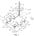
- FIG. 1 shows the production of a cell contacting system 2, of which the figure only shows a symbolic detail, which has a base body 4.
- FIG. A starting node 6 is stationary on the base body 4 and eight guide elements 8a-h, here pins or laying pins, are arranged temporarily or permanently.
- a guide head 12 is provided in the form of a laying head with a wire guide nozzle. This can be moved in all three spatial directions x, y and z.
- the guide head 12 or the wire guide nozzle has a dispensing opening 14 for dispensing an electrical conductor 16 in the direction of the arrow 18 .
- the guide head 12 is guided mechanically in the direction of the arrow 22 by a robot arm (not shown) along a path 20 specified by the program and only indicated here. As a result, it moves relative to the base body 4.
- the conductor 16 is discharged from the guide head 12 in the direction of the arrow 18 and laid on the base body 4 in order to form the low-voltage paths 10a, b.
- the conductor 16 here a wire
- the conductor 16 is fixed at the starting point 26 of the first low-voltage path 10a by an auxiliary device, the guide head 12 or laying head or - as here - by a geometry suitable for the connection, here the starting node 6 in the form of a welding fork .
- the conductor 16 is then guided through the tool suitable for this purpose, in this case the guide head 12 or the wire guide nozzle.
- the path 20 can be freely determined in all degrees of freedom.
- the movement of the guide head 12 and the payout of the conductor 16 from the guide head 12 and the payout opening 14, respectively, is performed automatically by a programmable control program.
- the wire tension is kept at an approximately constant value by a wire tension brake (not shown) upstream of the guide head 12 in the opposite direction of the arrow 18 .
- the train is held in relation to the ladder section 7 already fixed at the start node 6 .
- the starting knot 6 is therefore a winding fork here.
- the guide elements 8a-c serve to guide or fix the low-voltage path 10a along a desired course.
- the conductor 16 is in turn fixed by a suitable connection, here a fixing wrapping around the guide element 8d.
- the latter thus forms an end node 30 for the low-voltage path 10a.
- the guide element 8d (like the guide element 8e, see below) can therefore also be a guide and/or contact element.
- the conductor 16 is thus continued without interruption to the guide element 8e, without the wire tension lose, and there - fixed - again by fixing wrapping on the guide element 8e.
- the latter forms the starting point 26 of the second low-voltage path 10b.
- the endless wire in the form of the conductor 16 is separated at the appropriate points, i.e. between the two low-voltage paths 10a,b, and the wire remnants , i.e. the intermediate piece 24 of the conductor 16 that is no longer required and is shown in dashed lines is then removed.
- the conductor 16 is welded by an alternative contacting head 32, namely a welding head, to a counterpart 34, namely a contact plate, and is thereby electrically contacted.
Claims (11)
- Procédé de fabrication d'au moins un chemin à basse tension (10a, b) d'un système de contact de cellule (2), le système de contact de cellule (2) contenant un corps de base (4), dans lequel :- une tête de guidage (12) avec une ouverture de sortie (14) est fournie pour la sortie d'un conducteur électrique (16),- la tête de guidage (12) est guidée mécaniquement selon une trajectoire prédéterminable (20) par rapport au corps de base (4), et le conducteur (16) est ainsi sorti de la tête de guidage (12) et posé sur le corps de base (4) pour former le trajet à basse tension (10a, b).
- Procédé selon la revendication 1,
caractérisé en ce que
le déplacement de la tête de guidage (12) et/ou la sortie du conducteur (16) de la tête de guidage (12) sont effectués automatiquement à l'aide d'un programme de commande programmable. - Procédé selon l'une quelconque des revendications précédentes,
caractérisé en ce que
le conducteur (16) est maintenu en traction par rapport à une section de conducteur (7) déjà fixée pendant la sortie de la tête de guidage (12). - Procédé selon l'une quelconque des revendications précédentes,
caractérisé en ce que
le conducteur (16), avant la pose sur le corps de base (4), est fixé à un nœud de départ (6) par rapport au corps de base (4) et/ou, après la pose sur le corps de base (4), est fixé à un nœud d'arrivée (30) par rapport au corps de base (4). - Procédé selon l'une quelconque des revendications précédentes,
caractérisé en ce que
le conducteur (16) est agencé sur au moins un élément de guidage (8a-h) pendant la pose sur le corps de base (4). - Procédé selon l'une quelconque des revendications 4 à 5,
caractérisé en ce que
un moyen de serrage et/ou un moyen de retenue et/ou une broche et/ou une barrière et/ou un canal et/ou un labyrinthe est utilisé en tant que nœud de départ (6) et/ou nœud d'arrivée (30) et/ou élément de guidage (8ah) . - Procédé selon l'une quelconque des revendications 4 à 6,
caractérisé en ce que
des nœuds de départ (6) et/ou des nœuds d'arrivée (30) et/ou un élément de guidage (8a-h) qui sont montés sur le corps de base (4) sont utilisés en tant que nœuds de départ (6) et/ou nœuds d'arrivée (30) et/ou élément de guidage (8a-h). - Procédé selon l'une quelconque des revendications précédentes,
caractérisé en ce que
un fil ou une ligne est utilisé(e) en tant que conducteur électrique (16). - Procédé selon l'une quelconque des revendications précédentes,
caractérisé en ce que
au moins deux trajets à basse tension (10a, b) sont fabriqués par le fait qu'un conducteur commun (16) est posé sans interruption sur le support de base (4) et ensuite séparé en les deux trajets à basse tension (10a, b) . - Procédé selon l'une quelconque des revendications précédentes,
caractérisé en ce que
la tête de guidage (12) contient une buse de guidage de fil. - Procédé selon l'une quelconque des revendications précédentes,
caractérisé en ce que
une tête de contact (32) déplacée mécaniquement est déplacée vers un conducteur (16) posé et la tête de contact (32) vient en contact électrique avec le conducteur (16) avec un contre-élément (34).
Applications Claiming Priority (2)
| Application Number | Priority Date | Filing Date | Title |
|---|---|---|---|
| DE102019000856.1A DE102019000856A1 (de) | 2019-02-06 | 2019-02-06 | Herstellen eines Niedervoltpfades eines Zellkontaktiersystems |
| PCT/EP2020/052561 WO2020161047A1 (fr) | 2019-02-06 | 2020-02-03 | Production d'un chemin de basse tension d'un système de contact de cellules |
Publications (2)
| Publication Number | Publication Date |
|---|---|
| EP3921885A1 EP3921885A1 (fr) | 2021-12-15 |
| EP3921885B1 true EP3921885B1 (fr) | 2022-11-23 |
Family
ID=69526218
Family Applications (1)
| Application Number | Title | Priority Date | Filing Date |
|---|---|---|---|
| EP20704221.9A Active EP3921885B1 (fr) | 2019-02-06 | 2020-02-03 | Production d'un chemin de basse tension d'un système de contact de cellules |
Country Status (5)
| Country | Link |
|---|---|
| US (1) | US20210344084A1 (fr) |
| EP (1) | EP3921885B1 (fr) |
| CN (1) | CN113261154A (fr) |
| DE (1) | DE102019000856A1 (fr) |
| WO (1) | WO2020161047A1 (fr) |
Families Citing this family (2)
| Publication number | Priority date | Publication date | Assignee | Title |
|---|---|---|---|---|
| DE102022207934A1 (de) | 2022-08-01 | 2024-02-01 | Leoni Bordnetz-Systeme Gmbh | Verfahren zur Herstellung eines elektrischen Leitungssatzes sowie elektri-scher Leitungssatz |
| DE102022122672A1 (de) | 2022-09-07 | 2024-03-07 | Bayerische Motoren Werke Aktiengesellschaft | Batteriemodul für ein Fahrzeug, Verfahren zur Herstellung des Batteriemoduls und ein Fahrzeug mit dem Batteriemodul |
Family Cites Families (12)
| Publication number | Priority date | Publication date | Assignee | Title |
|---|---|---|---|---|
| US3907007A (en) * | 1974-01-23 | 1975-09-23 | Western Electric Co | Apparatus and method for forming wires on a wire-receiving member |
| US3930524A (en) * | 1974-10-17 | 1976-01-06 | Tarbox John W | Harness making apparatus |
| JP2001160389A (ja) * | 1999-12-01 | 2001-06-12 | Toshiba Battery Co Ltd | リード折り曲げ装置 |
| CN101149659B (zh) * | 2006-09-20 | 2010-09-15 | 凌阳科技股份有限公司 | 触控输入装置、触摸定位装置及其方法 |
| JP5233599B2 (ja) * | 2008-11-06 | 2013-07-10 | 住友電装株式会社 | 電線布線用ヘッド装置及び電線布線装置 |
| JP5353539B2 (ja) * | 2009-08-05 | 2013-11-27 | 住友電装株式会社 | 電線布線用ヘッド装置及び電線布線装置 |
| JP5789984B2 (ja) * | 2011-01-12 | 2015-10-07 | 住友電装株式会社 | 布線装置 |
| JP5454626B2 (ja) * | 2012-06-26 | 2014-03-26 | 株式会社オートネットワーク技術研究所 | 配線モジュール |
| WO2016161075A1 (fr) * | 2015-04-02 | 2016-10-06 | Hutchinson Technology Incorporated | Système d'amenée et de fixation de fils pour suspensions d'objectifs d'appareils photo |
| DE102016102503A1 (de) * | 2016-02-12 | 2017-08-17 | Rheinisch-Westfälische Technische Hochschule Aachen (RWTH) | Verfahren zur Herstellung eines Stents und Stent |
| JP2018006309A (ja) * | 2016-06-28 | 2018-01-11 | 株式会社オートネットワーク技術研究所 | ワイヤーハーネスの製造方法及び電線端末加工装置 |
| DE102016219999A1 (de) * | 2016-10-13 | 2018-04-19 | Robert Bosch Gmbh | Kabelbaum |
-
2019
- 2019-02-06 DE DE102019000856.1A patent/DE102019000856A1/de not_active Withdrawn
-
2020
- 2020-02-03 CN CN202080008098.9A patent/CN113261154A/zh active Pending
- 2020-02-03 EP EP20704221.9A patent/EP3921885B1/fr active Active
- 2020-02-03 WO PCT/EP2020/052561 patent/WO2020161047A1/fr unknown
-
2021
- 2021-07-12 US US17/372,603 patent/US20210344084A1/en active Pending
Also Published As
| Publication number | Publication date |
|---|---|
| US20210344084A1 (en) | 2021-11-04 |
| CN113261154A (zh) | 2021-08-13 |
| WO2020161047A1 (fr) | 2020-08-13 |
| EP3921885A1 (fr) | 2021-12-15 |
| DE102019000856A1 (de) | 2020-08-06 |
Similar Documents
| Publication | Publication Date | Title |
|---|---|---|
| DE112017000932B4 (de) | Kabelbaumstruktur | |
| EP3921885B1 (fr) | Production d'un chemin de basse tension d'un système de contact de cellules | |
| DE112011101263T5 (de) | Drahtverbindungsverfahren und Kabelbaum | |
| DE2361442A1 (de) | Elektrische kupplung und verfahren zur kontaktherstellung | |
| EP3891021B1 (fr) | Procédé de fabrication pour un réseau de bord d'un véhicule ainsi que réseau de bord de véhicule | |
| DE102009017052B3 (de) | Verbindungsvorrichtung für ein photovoltaisches Solarmodul, Verfahren zu deren Herstellung sowie Solaranlage mit einer solchen Verbindungsvorrichtung | |
| DE10247855A1 (de) | Kabelstrang und Fahrzeugmodul, das diesen umfasst | |
| DE19625974C1 (de) | Verfahren zur Herstellung eines vorgefertigten Türmoduls für eine Kraftfahrzeugtür | |
| WO2014076172A1 (fr) | Faisceau de câbles et procédé pour le fabriquer | |
| DE10216026A1 (de) | Anschlußkasten und Kabelbaum-Verbindungsverfahren | |
| EP2711726B1 (fr) | Dispositif de surveillance de tension | |
| EP1238443B1 (fr) | Procede pour equiper un objet d'un faisceau de cables constitue d'au moins un conducteur plat et appareils electriques/electroniques connectes a celui-ci | |
| EP3236544B1 (fr) | Procédé de regroupement de conduites individuelles d'un faisceau de câbles | |
| DE3510370A1 (de) | Verfahren zum verbinden von zwei elektrischen leitungen | |
| DE4238867C2 (de) | Vorrichtung und Verfahren zum Anschließen von mehreren elektrischen Verbrauchern | |
| DE202021000135U1 (de) | System zur automatisierten Herstellung von Kabeln und Kabelbäumen | |
| EP1251605A1 (fr) | Appareil et méthode pour l'insertion de bout de câble dans des boítiers de connecteurs | |
| DE102017125687B3 (de) | Dezentraler kleinverteiler, leitungssystem und herstellverfahren | |
| DE112020006487T5 (de) | Leiterplatte für Statorwicklungen mit integrierten Sicherungsstrukturen | |
| WO2020216834A1 (fr) | Procédé, dispositif et système pour confectionner un câble électrique | |
| EP0444032B1 (fr) | Procede et dispositif de fabrication d'harnais de cables | |
| DE102006005940B3 (de) | Kontaktvorrichtung | |
| AT503637B1 (de) | Kabel mit steckverbinder, steckverbinder für ein kabel und verfahren zum verbinden eines kabels mit einem steckverbinder | |
| EP3700018B1 (fr) | Dispositif de contact direct pour cartes de circuit imprimé permettant de produire un contact électrique, ainsi que carte de circuit imprimé et appareil électrique | |
| DE4238747C2 (de) | Anordnung zur Verbindung von Koaxialleitungen für koaxiale Hochfrequenzsteckverbindungen |
Legal Events
| Date | Code | Title | Description |
|---|---|---|---|
| STAA | Information on the status of an ep patent application or granted ep patent |
Free format text: STATUS: UNKNOWN |
|
| STAA | Information on the status of an ep patent application or granted ep patent |
Free format text: STATUS: THE INTERNATIONAL PUBLICATION HAS BEEN MADE |
|
| PUAI | Public reference made under article 153(3) epc to a published international application that has entered the european phase |
Free format text: ORIGINAL CODE: 0009012 |
|
| STAA | Information on the status of an ep patent application or granted ep patent |
Free format text: STATUS: REQUEST FOR EXAMINATION WAS MADE |
|
| 17P | Request for examination filed |
Effective date: 20210726 |
|
| AK | Designated contracting states |
Kind code of ref document: A1 Designated state(s): AL AT BE BG CH CY CZ DE DK EE ES FI FR GB GR HR HU IE IS IT LI LT LU LV MC MK MT NL NO PL PT RO RS SE SI SK SM TR |
|
| DAV | Request for validation of the european patent (deleted) | ||
| DAX | Request for extension of the european patent (deleted) | ||
| REG | Reference to a national code |
Ref country code: DE Ref legal event code: R079 Ref document number: 502020002062 Country of ref document: DE Free format text: PREVIOUS MAIN CLASS: H01M0002200000 Ipc: H01M0010480000 |
|
| GRAP | Despatch of communication of intention to grant a patent |
Free format text: ORIGINAL CODE: EPIDOSNIGR1 |
|
| STAA | Information on the status of an ep patent application or granted ep patent |
Free format text: STATUS: GRANT OF PATENT IS INTENDED |
|
| INTG | Intention to grant announced |
Effective date: 20220822 |
|
| RIC1 | Information provided on ipc code assigned before grant |
Ipc: H01M 50/50 20210101ALI20220805BHEP Ipc: H01B 13/012 20060101ALI20220805BHEP Ipc: B21F 45/00 20060101ALI20220805BHEP Ipc: B21F 23/00 20060101ALI20220805BHEP Ipc: H01M 10/48 20060101AFI20220805BHEP |
|
| GRAS | Grant fee paid |
Free format text: ORIGINAL CODE: EPIDOSNIGR3 |
|
| GRAA | (expected) grant |
Free format text: ORIGINAL CODE: 0009210 |
|
| STAA | Information on the status of an ep patent application or granted ep patent |
Free format text: STATUS: THE PATENT HAS BEEN GRANTED |
|
| AK | Designated contracting states |
Kind code of ref document: B1 Designated state(s): AL AT BE BG CH CY CZ DE DK EE ES FI FR GB GR HR HU IE IS IT LI LT LU LV MC MK MT NL NO PL PT RO RS SE SI SK SM TR |
|
| REG | Reference to a national code |
Ref country code: GB Ref legal event code: FG4D Free format text: NOT ENGLISH |
|
| REG | Reference to a national code |
Ref country code: CH Ref legal event code: EP |
|
| REG | Reference to a national code |
Ref country code: AT Ref legal event code: REF Ref document number: 1533705 Country of ref document: AT Kind code of ref document: T Effective date: 20221215 Ref country code: DE Ref legal event code: R096 Ref document number: 502020002062 Country of ref document: DE |
|
| REG | Reference to a national code |
Ref country code: IE Ref legal event code: FG4D Free format text: LANGUAGE OF EP DOCUMENT: GERMAN |
|
| REG | Reference to a national code |
Ref country code: LT Ref legal event code: MG9D |
|
| REG | Reference to a national code |
Ref country code: NL Ref legal event code: MP Effective date: 20221123 |
|
| PG25 | Lapsed in a contracting state [announced via postgrant information from national office to epo] |
Ref country code: SE Free format text: LAPSE BECAUSE OF FAILURE TO SUBMIT A TRANSLATION OF THE DESCRIPTION OR TO PAY THE FEE WITHIN THE PRESCRIBED TIME-LIMIT Effective date: 20221123 Ref country code: PT Free format text: LAPSE BECAUSE OF FAILURE TO SUBMIT A TRANSLATION OF THE DESCRIPTION OR TO PAY THE FEE WITHIN THE PRESCRIBED TIME-LIMIT Effective date: 20230323 Ref country code: NO Free format text: LAPSE BECAUSE OF FAILURE TO SUBMIT A TRANSLATION OF THE DESCRIPTION OR TO PAY THE FEE WITHIN THE PRESCRIBED TIME-LIMIT Effective date: 20230223 Ref country code: LT Free format text: LAPSE BECAUSE OF FAILURE TO SUBMIT A TRANSLATION OF THE DESCRIPTION OR TO PAY THE FEE WITHIN THE PRESCRIBED TIME-LIMIT Effective date: 20221123 Ref country code: FI Free format text: LAPSE BECAUSE OF FAILURE TO SUBMIT A TRANSLATION OF THE DESCRIPTION OR TO PAY THE FEE WITHIN THE PRESCRIBED TIME-LIMIT Effective date: 20221123 Ref country code: ES Free format text: LAPSE BECAUSE OF FAILURE TO SUBMIT A TRANSLATION OF THE DESCRIPTION OR TO PAY THE FEE WITHIN THE PRESCRIBED TIME-LIMIT Effective date: 20221123 |
|
| PGFP | Annual fee paid to national office [announced via postgrant information from national office to epo] |
Ref country code: FR Payment date: 20230221 Year of fee payment: 4 |
|
| PG25 | Lapsed in a contracting state [announced via postgrant information from national office to epo] |
Ref country code: RS Free format text: LAPSE BECAUSE OF FAILURE TO SUBMIT A TRANSLATION OF THE DESCRIPTION OR TO PAY THE FEE WITHIN THE PRESCRIBED TIME-LIMIT Effective date: 20221123 Ref country code: PL Free format text: LAPSE BECAUSE OF FAILURE TO SUBMIT A TRANSLATION OF THE DESCRIPTION OR TO PAY THE FEE WITHIN THE PRESCRIBED TIME-LIMIT Effective date: 20221123 Ref country code: LV Free format text: LAPSE BECAUSE OF FAILURE TO SUBMIT A TRANSLATION OF THE DESCRIPTION OR TO PAY THE FEE WITHIN THE PRESCRIBED TIME-LIMIT Effective date: 20221123 Ref country code: IS Free format text: LAPSE BECAUSE OF FAILURE TO SUBMIT A TRANSLATION OF THE DESCRIPTION OR TO PAY THE FEE WITHIN THE PRESCRIBED TIME-LIMIT Effective date: 20230323 Ref country code: HR Free format text: LAPSE BECAUSE OF FAILURE TO SUBMIT A TRANSLATION OF THE DESCRIPTION OR TO PAY THE FEE WITHIN THE PRESCRIBED TIME-LIMIT Effective date: 20221123 Ref country code: GR Free format text: LAPSE BECAUSE OF FAILURE TO SUBMIT A TRANSLATION OF THE DESCRIPTION OR TO PAY THE FEE WITHIN THE PRESCRIBED TIME-LIMIT Effective date: 20230224 |
|
| PGFP | Annual fee paid to national office [announced via postgrant information from national office to epo] |
Ref country code: IT Payment date: 20230228 Year of fee payment: 4 |
|
| PG25 | Lapsed in a contracting state [announced via postgrant information from national office to epo] |
Ref country code: NL Free format text: LAPSE BECAUSE OF FAILURE TO SUBMIT A TRANSLATION OF THE DESCRIPTION OR TO PAY THE FEE WITHIN THE PRESCRIBED TIME-LIMIT Effective date: 20221123 |
|
| P01 | Opt-out of the competence of the unified patent court (upc) registered |
Effective date: 20230526 |
|
| PG25 | Lapsed in a contracting state [announced via postgrant information from national office to epo] |
Ref country code: SM Free format text: LAPSE BECAUSE OF FAILURE TO SUBMIT A TRANSLATION OF THE DESCRIPTION OR TO PAY THE FEE WITHIN THE PRESCRIBED TIME-LIMIT Effective date: 20221123 Ref country code: RO Free format text: LAPSE BECAUSE OF FAILURE TO SUBMIT A TRANSLATION OF THE DESCRIPTION OR TO PAY THE FEE WITHIN THE PRESCRIBED TIME-LIMIT Effective date: 20221123 Ref country code: EE Free format text: LAPSE BECAUSE OF FAILURE TO SUBMIT A TRANSLATION OF THE DESCRIPTION OR TO PAY THE FEE WITHIN THE PRESCRIBED TIME-LIMIT Effective date: 20221123 Ref country code: DK Free format text: LAPSE BECAUSE OF FAILURE TO SUBMIT A TRANSLATION OF THE DESCRIPTION OR TO PAY THE FEE WITHIN THE PRESCRIBED TIME-LIMIT Effective date: 20221123 Ref country code: CZ Free format text: LAPSE BECAUSE OF FAILURE TO SUBMIT A TRANSLATION OF THE DESCRIPTION OR TO PAY THE FEE WITHIN THE PRESCRIBED TIME-LIMIT Effective date: 20221123 |
|
| PGFP | Annual fee paid to national office [announced via postgrant information from national office to epo] |
Ref country code: DE Payment date: 20230412 Year of fee payment: 4 |
|
| REG | Reference to a national code |
Ref country code: DE Ref legal event code: R097 Ref document number: 502020002062 Country of ref document: DE |
|
| PG25 | Lapsed in a contracting state [announced via postgrant information from national office to epo] |
Ref country code: SK Free format text: LAPSE BECAUSE OF FAILURE TO SUBMIT A TRANSLATION OF THE DESCRIPTION OR TO PAY THE FEE WITHIN THE PRESCRIBED TIME-LIMIT Effective date: 20221123 Ref country code: AL Free format text: LAPSE BECAUSE OF FAILURE TO SUBMIT A TRANSLATION OF THE DESCRIPTION OR TO PAY THE FEE WITHIN THE PRESCRIBED TIME-LIMIT Effective date: 20221123 |
|
| PG25 | Lapsed in a contracting state [announced via postgrant information from national office to epo] |
Ref country code: MC Free format text: LAPSE BECAUSE OF FAILURE TO SUBMIT A TRANSLATION OF THE DESCRIPTION OR TO PAY THE FEE WITHIN THE PRESCRIBED TIME-LIMIT Effective date: 20221123 |
|
| PLBE | No opposition filed within time limit |
Free format text: ORIGINAL CODE: 0009261 |
|
| REG | Reference to a national code |
Ref country code: CH Ref legal event code: PL |
|
| STAA | Information on the status of an ep patent application or granted ep patent |
Free format text: STATUS: NO OPPOSITION FILED WITHIN TIME LIMIT |
|
| REG | Reference to a national code |
Ref country code: BE Ref legal event code: MM Effective date: 20230228 |
|
| PG25 | Lapsed in a contracting state [announced via postgrant information from national office to epo] |
Ref country code: LU Free format text: LAPSE BECAUSE OF NON-PAYMENT OF DUE FEES Effective date: 20230203 Ref country code: LI Free format text: LAPSE BECAUSE OF NON-PAYMENT OF DUE FEES Effective date: 20230228 Ref country code: CH Free format text: LAPSE BECAUSE OF NON-PAYMENT OF DUE FEES Effective date: 20230228 |
|
| 26N | No opposition filed |
Effective date: 20230824 |
|
| PG25 | Lapsed in a contracting state [announced via postgrant information from national office to epo] |
Ref country code: SI Free format text: LAPSE BECAUSE OF FAILURE TO SUBMIT A TRANSLATION OF THE DESCRIPTION OR TO PAY THE FEE WITHIN THE PRESCRIBED TIME-LIMIT Effective date: 20221123 |
|
| REG | Reference to a national code |
Ref country code: IE Ref legal event code: MM4A |
|
| REG | Reference to a national code |
Ref country code: GB Ref legal event code: 732E Free format text: REGISTERED BETWEEN 20231228 AND 20240103 |
|
| PG25 | Lapsed in a contracting state [announced via postgrant information from national office to epo] |
Ref country code: IE Free format text: LAPSE BECAUSE OF NON-PAYMENT OF DUE FEES Effective date: 20230203 |
|
| REG | Reference to a national code |
Ref country code: DE Ref legal event code: R081 Ref document number: 502020002062 Country of ref document: DE Owner name: DIEHL ADVANCED MOBILITY GMBH, DE Free format text: FORMER OWNER: DIEHL METAL APPLICATIONS GMBH, 90552 ROETHENBACH, DE |
|
| PG25 | Lapsed in a contracting state [announced via postgrant information from national office to epo] |
Ref country code: BE Free format text: LAPSE BECAUSE OF NON-PAYMENT OF DUE FEES Effective date: 20230228 |