EP0697493B1 - An einem Halterahmen angeordnete Isolierglasscheibe - Google Patents
An einem Halterahmen angeordnete Isolierglasscheibe Download PDFInfo
- Publication number
- EP0697493B1 EP0697493B1 EP95111134A EP95111134A EP0697493B1 EP 0697493 B1 EP0697493 B1 EP 0697493B1 EP 95111134 A EP95111134 A EP 95111134A EP 95111134 A EP95111134 A EP 95111134A EP 0697493 B1 EP0697493 B1 EP 0697493B1
- Authority
- EP
- European Patent Office
- Prior art keywords
- perforations
- insulating glass
- glass pane
- frame
- bonding back
- Prior art date
- Legal status (The legal status is an assumption and is not a legal conclusion. Google has not performed a legal analysis and makes no representation as to the accuracy of the status listed.)
- Expired - Lifetime
Links
- 239000011521 glass Substances 0.000 claims abstract description 44
- 239000012790 adhesive layer Substances 0.000 claims abstract description 6
- 238000007789 sealing Methods 0.000 claims description 8
- 239000002131 composite material Substances 0.000 abstract description 20
- 238000007688 edging Methods 0.000 description 3
- 239000000565 sealant Substances 0.000 description 2
- 125000006850 spacer group Chemical group 0.000 description 2
- 230000003068 static effect Effects 0.000 description 2
- 239000000853 adhesive Substances 0.000 description 1
- 239000013466 adhesive and sealant Substances 0.000 description 1
- 230000001070 adhesive effect Effects 0.000 description 1
- 238000005253 cladding Methods 0.000 description 1
- 238000010276 construction Methods 0.000 description 1
- 230000008030 elimination Effects 0.000 description 1
- 238000003379 elimination reaction Methods 0.000 description 1
- 238000001704 evaporation Methods 0.000 description 1
- 230000008020 evaporation Effects 0.000 description 1
- 239000003292 glue Substances 0.000 description 1
- 238000002955 isolation Methods 0.000 description 1
- 239000010410 layer Substances 0.000 description 1
- 238000002386 leaching Methods 0.000 description 1
- 230000001404 mediated effect Effects 0.000 description 1
- 230000002093 peripheral effect Effects 0.000 description 1
- 230000035939 shock Effects 0.000 description 1
- 239000013589 supplement Substances 0.000 description 1
- 238000013022 venting Methods 0.000 description 1
- XLYOFNOQVPJJNP-UHFFFAOYSA-N water Chemical compound O XLYOFNOQVPJJNP-UHFFFAOYSA-N 0.000 description 1
Images
Classifications
-
- E—FIXED CONSTRUCTIONS
- E06—DOORS, WINDOWS, SHUTTERS, OR ROLLER BLINDS IN GENERAL; LADDERS
- E06B—FIXED OR MOVABLE CLOSURES FOR OPENINGS IN BUILDINGS, VEHICLES, FENCES OR LIKE ENCLOSURES IN GENERAL, e.g. DOORS, WINDOWS, BLINDS, GATES
- E06B3/00—Window sashes, door leaves, or like elements for closing wall or like openings; Layout of fixed or moving closures, e.g. windows in wall or like openings; Features of rigidly-mounted outer frames relating to the mounting of wing frames
- E06B3/54—Fixing of glass panes or like plates
- E06B3/56—Fixing of glass panes or like plates by means of putty, cement, or adhesives only
-
- E—FIXED CONSTRUCTIONS
- E06—DOORS, WINDOWS, SHUTTERS, OR ROLLER BLINDS IN GENERAL; LADDERS
- E06B—FIXED OR MOVABLE CLOSURES FOR OPENINGS IN BUILDINGS, VEHICLES, FENCES OR LIKE ENCLOSURES IN GENERAL, e.g. DOORS, WINDOWS, BLINDS, GATES
- E06B3/00—Window sashes, door leaves, or like elements for closing wall or like openings; Layout of fixed or moving closures, e.g. windows in wall or like openings; Features of rigidly-mounted outer frames relating to the mounting of wing frames
- E06B3/54—Fixing of glass panes or like plates
- E06B3/5409—Means for locally spacing the pane from the surrounding frame
-
- E—FIXED CONSTRUCTIONS
- E06—DOORS, WINDOWS, SHUTTERS, OR ROLLER BLINDS IN GENERAL; LADDERS
- E06B—FIXED OR MOVABLE CLOSURES FOR OPENINGS IN BUILDINGS, VEHICLES, FENCES OR LIKE ENCLOSURES IN GENERAL, e.g. DOORS, WINDOWS, BLINDS, GATES
- E06B7/00—Special arrangements or measures in connection with doors or windows
- E06B7/14—Measures for draining-off condensed water or water leaking-in frame members for draining off condensation water, throats at the bottom of a sash
-
- E—FIXED CONSTRUCTIONS
- E06—DOORS, WINDOWS, SHUTTERS, OR ROLLER BLINDS IN GENERAL; LADDERS
- E06B—FIXED OR MOVABLE CLOSURES FOR OPENINGS IN BUILDINGS, VEHICLES, FENCES OR LIKE ENCLOSURES IN GENERAL, e.g. DOORS, WINDOWS, BLINDS, GATES
- E06B3/00—Window sashes, door leaves, or like elements for closing wall or like openings; Layout of fixed or moving closures, e.g. windows in wall or like openings; Features of rigidly-mounted outer frames relating to the mounting of wing frames
- E06B3/54—Fixing of glass panes or like plates
- E06B3/5454—Fixing of glass panes or like plates inside U-shaped section members
Definitions
- the invention relates to a on a holding frame arranged insulating glass pane for windows, facades and the like.
- DE-U-85 05 873 describes a thermally insulated window, in which with the elimination of the isolation zone only one inner glass support frame is provided on which the Glazing is held by an edging profile. This also eliminates the need for the glass retaining strip, which means that Result a reduction in the frame width is achieved.
- the end faces of the glazing are sealed on the inside with a sealing strip and on the outside by a layer arranged on the edge border profile an adhesive or sealant.
- the edging profile can however also be provided with holes, which then the Venting and / or drainage to the glazing subsequent cavity serve. However, this must be sufficient free space between the composite backing of the Insulating glass pane and the one facing it Frame part of the holding frame must be present.
- DE-U-85 05 873 describes the Possibility to glue this cavity with or Fill sealant, but then no holes are provided in the edging profile.
- the invention has for its object a Form insulating glass pane with a holding frame so that the required as moisture and moisture protection Distance between the composite back and the frame part is unnecessary, so that the holding frame as a whole can be kept correspondingly smaller without doing so however the thermal properties in the range of Deteriorate frame part.
- a on a holding frame arranged insulating glass pane in which the Holding frame at least one the insulating glass pane frame part covering the edge of its composite back has and the insulating glass pane from two to each other parallel, one filled with gas between them Gap enclosing glass panes, which on Edge are glued together by a sealing strip, so that the sealing strip and the peripheral surfaces of the two Glass panes together the composite back of the Form insulating glass pane.
- Frame part covering the composite back of the insulating glass pane of the holder frame from along the composite back arranged perforations is broken, and wherein between the composite back and the frame part continuous, thin adhesive layer provided that fills the perforations and there with that of Composite back side of the frame part in essentially flush, with the perforations separated from each other by narrow cross bars are whose width is smaller than that in the same Direction measured width of the perforations.
- the distance between the composite back and the frame part essential can be reduced. At most it is still necessary a narrow gap for inserting supplements for Protect the glass edges of the insulating glass panes. Except of the perforations according to the invention in the Cover the composite back of the insulating glass pane Frame part is within the scope of the invention with respect to Training of the holding frame largely extensive Freedom. Esp. can the holding frame only the Insulating glass pane surrounding adapter frame for connection to a load-bearing frame construction or an immediate part of this supporting structure itself, be it on one fixed facade cladding or on sash frames from Windows and doors.
- the perforations themselves can be different Have cross-sectional shapes.
- In addition to circular Perforation cross-section are primarily perforations advantageous, each a square or have a rectangular cross-section. It is about Perforations with a rectangular cross-section, so recommended it, the perforations towards their longer ones To line up the side of the rectangle.
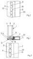
- the insulating glass pane 1 usually consists of two parallel, between them a space filled with gas 3 enclosing glass panes 4, which in the edge area Spacers 5 kept at a distance from each other and on the outside on the outside of the spacers 5 a sealing strip 6 made of adhesive and sealant together are glued so that the sealing strip 6 and the Edge surfaces 7 of the two glass panes 4 together generally designated 8 composite back of the Form insulating glass pane 1.
- the holding frame has at least one edge of the insulating glass pane 1 its composite back 8 covering frame part 9, the Perforations 10 arranged along the composite back 8 is broken.
- perforations 10 can circular cross section, as in Fig. 4, square Cross section as in Fig. 2 or rectangular cross section as in Fig. 3. In the case of rectangular Cross-section, as in Fig. 3, the perforations 10 in Lined up in the direction of their longer rectangle side.
- the Perforations 10 are through narrow crossbars 11 separated from each other.
- a continuous adhesive layer 14 with the Sealing strip 6 can also be formed in one piece homogeneously can.
- This adhesive layer 14 fills the gap between the Frame part 9 and the edge surfaces 7 of the glass panes 4 and the perforations 10 so that moisture or moisture only on the in the perforations 10 essentially flush with the frame part 9, from the composite backing 8 open surfaces of the adhesive layer 14 facing away where they can occur through leaching and evaporation can be removed quickly.
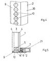
- the Holding frame an adapter frame that connects to a statically supporting frame 21 mediated.
- the holding frame can, for example, also be a static one Element and for its static function with a Hollow profile 20, as indicated in FIGS. 2 to 5 is equipped.
- Insulating glass pane 1 for simplicity only each consisting of two individual glass panes 4 is shown, does exist within the scope of the invention of course the possibility of one or both the glass panes 4, for example made of heat protection glass to exist or multiple insulating glass (three spaced washers and more) to use.
Landscapes
- Engineering & Computer Science (AREA)
- Civil Engineering (AREA)
- Structural Engineering (AREA)
- Securing Of Glass Panes Or The Like (AREA)
- Joining Of Glass To Other Materials (AREA)
Description
- Fig. 1
- einen Teil einer Isolierglasscheibe mit dem unteren horizontalen Rahmenschenkel eines Tragrahmens im Querschnitt,
- Fig. 2
- eine Ansicht des Rahmenschenkels nach Fig. 1 von unten,
- Fig. 3
- eine andere Ausführungsform des Gegenstandes der Fig. 2,
- Fig. 4
- eine nochmals andere Ausführungsform des Gegenstandes der Fig. 2 und 3,
- Fig. 5
- eine andere Ausführungsform der am Halterahmen angeordneten Isolierglasscheibe in einer der Fig. 1 entsprechenden Darstellung.
Claims (3)
- An einem Halterahmen angeordnete Isolierglasscheibe (1) für Fenster, Fassaden und dergleichen, wobei der Halterahmen mindestens einen die Isolierglasscheibe (1) randseitig an ihrem Verbundrücken (8) abdeckenden Rahmenteil (9) aufweist und die Isolierglasscheibe (1) aus zwei zueinander parallelen, zwischen sich einen mit Gas gefüllten Zwischenraum (3) einschließenden Glasscheiben (4) besteht, die am Rand durch eine Dichtleiste (6) miteinander verklebt sind, so daß die Dichtleiste (6) und die Randflächen (7) der beiden Glasscheiben (4) gemeinsam den Verbundrücken (8) der Isolierglasscheibe (1) bilden, wobei ferner der den Verbundrücken (8) der Isolierglasscheibe (1) abdeckende Rahmenteil (9) des Halterrahmens von längs des Verbundrückens (8) angeordneten Perforationen (10) durchbrochen ist, und wobei zwischen dem Verbundrücken (8) und dem Rahmenteil (9) eine durchgängige, dünn ausgebildete Klebeschicht (14) vorgesehen ist, die die Perforationen (10) füllt und dort mit der vom Verbundrücken (8) abgewandten Seite des Rahmenteils (9) im wesentlichen bündig abschließt, wobei die Perforationen (10) durch schmal ausgebildete Querstege (11) voneinander getrennt sind, deren Breite kleiner ist als die in gleicher Richtung gemessene Breite der Perforationen (10).
- Isolierglasscheibe nach Anspruch 1, dadurch gekennzeichnet, daß die Perforationen (10) jeweils einen quadratischen oder rechteckigen Querschnitt besitzen.
- Isolierglasscheibe nach Anspruch 2, dadurch gekennzeichnet, daß bei rechteckigem Perforationsquerschnitt die Perforationen (10) in Richtung ihrer längeren Rechteckseite gereiht sind.
Applications Claiming Priority (2)
| Application Number | Priority Date | Filing Date | Title |
|---|---|---|---|
| DE4429666A DE4429666C2 (de) | 1994-08-20 | 1994-08-20 | An einem Halterahmen angeordnete Isolierglasscheibe |
| DE4429666 | 1994-08-20 |
Publications (2)
| Publication Number | Publication Date |
|---|---|
| EP0697493A1 EP0697493A1 (de) | 1996-02-21 |
| EP0697493B1 true EP0697493B1 (de) | 2001-10-17 |
Family
ID=6526230
Family Applications (1)
| Application Number | Title | Priority Date | Filing Date |
|---|---|---|---|
| EP95111134A Expired - Lifetime EP0697493B1 (de) | 1994-08-20 | 1995-07-15 | An einem Halterahmen angeordnete Isolierglasscheibe |
Country Status (6)
| Country | Link |
|---|---|
| EP (1) | EP0697493B1 (de) |
| AT (1) | ATE207185T1 (de) |
| DE (2) | DE4429666C2 (de) |
| DK (1) | DK0697493T3 (de) |
| ES (1) | ES2161808T3 (de) |
| PT (1) | PT697493E (de) |
Families Citing this family (2)
| Publication number | Priority date | Publication date | Assignee | Title |
|---|---|---|---|---|
| US7520093B2 (en) * | 2004-01-13 | 2009-04-21 | Beat Guhl | Frame construction of a sliding door |
| DE102009044892A1 (de) * | 2009-12-14 | 2011-06-16 | Kömmerling Chemische Fabrik GmbH | Fenster oder Tür |
Family Cites Families (12)
| Publication number | Priority date | Publication date | Assignee | Title |
|---|---|---|---|---|
| CH471952A (fr) * | 1968-03-08 | 1969-04-30 | Felix Andre | Assemblage d'éléments de construction métalliques pour façades de bâtiments |
| DE2502584A1 (de) * | 1975-01-23 | 1976-07-29 | Ritter Aluminium Gmbh | Waermegedaemmtes aluminiumfenster |
| GB1539504A (en) * | 1976-09-22 | 1979-01-31 | Yoshida Kogyo Kk | Water-drainable gasket |
| DE2905191A1 (de) * | 1979-02-12 | 1980-08-21 | Straub Theodor | Profilkonstruktion |
| DE3128273A1 (de) * | 1980-08-08 | 1982-03-18 | F.W. Brökelmann Aluminiumwerk KG, 5760 Arnsberg | "verfahren zur herstellung von profilen sowie dazugehoeriges verbundprofil" |
| US4447985A (en) * | 1982-06-16 | 1984-05-15 | Wausau Metals Corporation | Window structure |
| CH662614A5 (de) * | 1984-03-02 | 1987-10-15 | Daetwyler Ag | Profilleiste zum dichtenden einfassen einer fensterscheibe oder eines tuerelementes. |
| DE8505873U1 (de) * | 1985-03-01 | 1986-03-27 | Nahr, Helmar, Dr.Dr., 8530 Neustadt | Wärmegedämmtes Fenster oder entsprechende, verglaste Tür |
| BE902746A (fr) * | 1985-06-26 | 1985-10-16 | Greant Joseph G J G | Chassis de fenetres ou de murs rideaux a dormants et ouvrants uniformes. |
| US4669241A (en) * | 1986-01-28 | 1987-06-02 | Thermatic Glass, Inc. | Thermal insulated and shock resistant window assembly |
| DE4022177A1 (de) * | 1990-07-12 | 1992-01-16 | Mbs Gemont Ag | Fenster- oder tuerkonstruktion |
| DK165559C (da) * | 1990-10-19 | 1993-04-26 | Rasmussen Kann Ind As | Rammekonstruktion navnlig til indadgaaende vinduer eller glasdoere |
-
1994
- 1994-08-20 DE DE4429666A patent/DE4429666C2/de not_active Expired - Fee Related
-
1995
- 1995-07-15 DK DK95111134T patent/DK0697493T3/da active
- 1995-07-15 AT AT95111134T patent/ATE207185T1/de not_active IP Right Cessation
- 1995-07-15 PT PT95111134T patent/PT697493E/pt unknown
- 1995-07-15 DE DE59509711T patent/DE59509711D1/de not_active Expired - Fee Related
- 1995-07-15 ES ES95111134T patent/ES2161808T3/es not_active Expired - Lifetime
- 1995-07-15 EP EP95111134A patent/EP0697493B1/de not_active Expired - Lifetime
Also Published As
| Publication number | Publication date |
|---|---|
| EP0697493A1 (de) | 1996-02-21 |
| PT697493E (pt) | 2002-01-30 |
| DE4429666C2 (de) | 1998-02-26 |
| DK0697493T3 (da) | 2001-12-03 |
| DE59509711D1 (de) | 2001-11-22 |
| ATE207185T1 (de) | 2001-11-15 |
| ES2161808T3 (es) | 2001-12-16 |
| DE4429666A1 (de) | 1996-02-22 |
Similar Documents
| Publication | Publication Date | Title |
|---|---|---|
| DE69020648T2 (de) | Isolierverglasung mit isolierendem Abstandshalter. | |
| DE3626194C2 (de) | Fassadenverkleidung | |
| EP2733295B1 (de) | Verglasungseinheit | |
| DE3125251A1 (de) | Oberlichtkonstruktion | |
| DE3541730A1 (de) | Verkleidung fuer aussenflaechen von gebaeuden | |
| EP0301166B1 (de) | Fassadenelement aus Glas | |
| DE4343521A1 (de) | Fenster- oder Türkonstruktion | |
| DE29607069U1 (de) | Isolierglasscheibe mit fotovoltaischem Element | |
| DE8505873U1 (de) | Wärmegedämmtes Fenster oder entsprechende, verglaste Tür | |
| DE2950348C2 (de) | ||
| EP0697493B1 (de) | An einem Halterahmen angeordnete Isolierglasscheibe | |
| DE3044179C2 (de) | Isolierglastafel mit einem elastischen, luft- und feuchtigkeitsdichten Distanzelement, das zwischen die Glasscheiben eingreift und mit seitlichen Ansätzen die Umfangskanten der Glasscheibe überlappt | |
| DE2707398A1 (de) | Verbundfenster | |
| WO1984000191A1 (fr) | Ensemble de pieces pour l'installation d'un vitrage isolant | |
| DE202016100994U1 (de) | Pfosten-Riegel-Konstruktion | |
| DD294757A5 (de) | Einrichtung zur verklotzung von scheiben in tuer- oder fensterrahmen | |
| DE3049356A1 (de) | Begrenzungsbauteil, insbesondere fenster, tuer oder trennwand | |
| CH688384A5 (de) | Glaselement mit integrierter Store. | |
| DE60024639T2 (de) | Isolierscheibe | |
| DE8418383U1 (de) | Isolierglasscheibe mit erneuerbaren entfeuchtungselementen | |
| DE7924256U1 (de) | Sprossenfenster mit isolierglas | |
| DE2824519C3 (de) | Verwendung einer wärme- und/oder schalldämmenden Isolierglasscheibe | |
| DE102023131759A1 (de) | Aufgehängte Zwischenscheibe in Verglasungseinheit aus Mehrfachisolierglas | |
| DE3830397A1 (de) | Rahmenkonstruktion in pfosten-riegel-bauweise, insbesondere fuer fassaden, daecher od. dgl. | |
| DE19707843A1 (de) | Gebäudeaußenfenster, insbesondere Lochfenster |
Legal Events
| Date | Code | Title | Description |
|---|---|---|---|
| PUAI | Public reference made under article 153(3) epc to a published international application that has entered the european phase |
Free format text: ORIGINAL CODE: 0009012 |
|
| AK | Designated contracting states |
Kind code of ref document: A1 Designated state(s): AT BE CH DE DK ES FR GB IT LI NL PT SE |
|
| RBV | Designated contracting states (corrected) |
Designated state(s): AT BE CH DE DK ES FR GB IT LI NL PT SE |
|
| 17P | Request for examination filed |
Effective date: 19960612 |
|
| 17Q | First examination report despatched |
Effective date: 19980129 |
|
| RAP1 | Party data changed (applicant data changed or rights of an application transferred) |
Owner name: NORSK HYDRO ASA |
|
| RAP1 | Party data changed (applicant data changed or rights of an application transferred) |
Owner name: NORSK HYDRO ASA |
|
| APAB | Appeal dossier modified |
Free format text: ORIGINAL CODE: EPIDOS NOAPE |
|
| APAB | Appeal dossier modified |
Free format text: ORIGINAL CODE: EPIDOS NOAPE |
|
| APAD | Appeal reference recorded |
Free format text: ORIGINAL CODE: EPIDOS REFNE |
|
| APCB | Communication from the board of appeal sent |
Free format text: ORIGINAL CODE: EPIDOS OBAPE |
|
| APCB | Communication from the board of appeal sent |
Free format text: ORIGINAL CODE: EPIDOS OBAPE |
|
| APAB | Appeal dossier modified |
Free format text: ORIGINAL CODE: EPIDOS NOAPE |
|
| GRAG | Despatch of communication of intention to grant |
Free format text: ORIGINAL CODE: EPIDOS AGRA |
|
| GRAH | Despatch of communication of intention to grant a patent |
Free format text: ORIGINAL CODE: EPIDOS IGRA |
|
| GRAH | Despatch of communication of intention to grant a patent |
Free format text: ORIGINAL CODE: EPIDOS IGRA |
|
| GRAA | (expected) grant |
Free format text: ORIGINAL CODE: 0009210 |
|
| AK | Designated contracting states |
Kind code of ref document: B1 Designated state(s): AT BE CH DE DK ES FR GB IT LI NL PT SE |
|
| REF | Corresponds to: |
Ref document number: 207185 Country of ref document: AT Date of ref document: 20011115 Kind code of ref document: T |
|
| REG | Reference to a national code |
Ref country code: CH Ref legal event code: NV Representative=s name: ISLER & PEDRAZZINI AG Ref country code: CH Ref legal event code: EP |
|
| REF | Corresponds to: |
Ref document number: 59509711 Country of ref document: DE Date of ref document: 20011122 |
|
| REG | Reference to a national code |
Ref country code: DK Ref legal event code: T3 |
|
| REG | Reference to a national code |
Ref country code: ES Ref legal event code: FG2A Ref document number: 2161808 Country of ref document: ES Kind code of ref document: T3 |
|
| ET | Fr: translation filed | ||
| REG | Reference to a national code |
Ref country code: GB Ref legal event code: IF02 |
|
| GBT | Gb: translation of ep patent filed (gb section 77(6)(a)/1977) |
Effective date: 20011224 |
|
| REG | Reference to a national code |
Ref country code: PT Ref legal event code: SC4A Free format text: AVAILABILITY OF NATIONAL TRANSLATION Effective date: 20011018 |
|
| PGFP | Annual fee paid to national office [announced via postgrant information from national office to epo] |
Ref country code: PT Payment date: 20020703 Year of fee payment: 8 |
|
| PGFP | Annual fee paid to national office [announced via postgrant information from national office to epo] |
Ref country code: SE Payment date: 20020705 Year of fee payment: 8 |
|
| PGFP | Annual fee paid to national office [announced via postgrant information from national office to epo] |
Ref country code: FR Payment date: 20020709 Year of fee payment: 8 |
|
| PGFP | Annual fee paid to national office [announced via postgrant information from national office to epo] |
Ref country code: GB Payment date: 20020710 Year of fee payment: 8 |
|
| PGFP | Annual fee paid to national office [announced via postgrant information from national office to epo] |
Ref country code: DK Payment date: 20020716 Year of fee payment: 8 |
|
| PGFP | Annual fee paid to national office [announced via postgrant information from national office to epo] |
Ref country code: ES Payment date: 20020726 Year of fee payment: 8 |
|
| PGFP | Annual fee paid to national office [announced via postgrant information from national office to epo] |
Ref country code: NL Payment date: 20020730 Year of fee payment: 8 |
|
| PLBE | No opposition filed within time limit |
Free format text: ORIGINAL CODE: 0009261 |
|
| STAA | Information on the status of an ep patent application or granted ep patent |
Free format text: STATUS: NO OPPOSITION FILED WITHIN TIME LIMIT |
|
| PGFP | Annual fee paid to national office [announced via postgrant information from national office to epo] |
Ref country code: BE Payment date: 20020919 Year of fee payment: 8 |
|
| 26N | No opposition filed | ||
| PG25 | Lapsed in a contracting state [announced via postgrant information from national office to epo] |
Ref country code: GB Free format text: LAPSE BECAUSE OF NON-PAYMENT OF DUE FEES Effective date: 20030715 |
|
| PG25 | Lapsed in a contracting state [announced via postgrant information from national office to epo] |
Ref country code: SE Free format text: LAPSE BECAUSE OF NON-PAYMENT OF DUE FEES Effective date: 20030716 Ref country code: ES Free format text: LAPSE BECAUSE OF NON-PAYMENT OF DUE FEES Effective date: 20030716 |
|
| PG25 | Lapsed in a contracting state [announced via postgrant information from national office to epo] |
Ref country code: DK Free format text: LAPSE BECAUSE OF NON-PAYMENT OF DUE FEES Effective date: 20030731 Ref country code: BE Free format text: LAPSE BECAUSE OF NON-PAYMENT OF DUE FEES Effective date: 20030731 |
|
| BERE | Be: lapsed |
Owner name: *NORSK HYDRO ASA Effective date: 20030731 |
|
| PG25 | Lapsed in a contracting state [announced via postgrant information from national office to epo] |
Ref country code: PT Free format text: LAPSE BECAUSE OF NON-PAYMENT OF DUE FEES Effective date: 20040131 |
|
| PG25 | Lapsed in a contracting state [announced via postgrant information from national office to epo] |
Ref country code: NL Free format text: LAPSE BECAUSE OF NON-PAYMENT OF DUE FEES Effective date: 20040201 |
|
| EUG | Se: european patent has lapsed | ||
| GBPC | Gb: european patent ceased through non-payment of renewal fee |
Effective date: 20030715 |
|
| REG | Reference to a national code |
Ref country code: DK Ref legal event code: EBP |
|
| PG25 | Lapsed in a contracting state [announced via postgrant information from national office to epo] |
Ref country code: FR Free format text: LAPSE BECAUSE OF NON-PAYMENT OF DUE FEES Effective date: 20040331 |
|
| NLV4 | Nl: lapsed or anulled due to non-payment of the annual fee |
Effective date: 20040201 |
|
| REG | Reference to a national code |
Ref country code: FR Ref legal event code: ST Ref country code: PT Ref legal event code: MM4A Free format text: LAPSE DUE TO NON-PAYMENT OF FEES Effective date: 20040131 |
|
| REG | Reference to a national code |
Ref country code: ES Ref legal event code: FD2A Effective date: 20030716 |
|
| PGFP | Annual fee paid to national office [announced via postgrant information from national office to epo] |
Ref country code: AT Payment date: 20050622 Year of fee payment: 11 |
|
| PGFP | Annual fee paid to national office [announced via postgrant information from national office to epo] |
Ref country code: DE Payment date: 20050707 Year of fee payment: 11 |
|
| PGFP | Annual fee paid to national office [announced via postgrant information from national office to epo] |
Ref country code: CH Payment date: 20050713 Year of fee payment: 11 |
|
| PG25 | Lapsed in a contracting state [announced via postgrant information from national office to epo] |
Ref country code: IT Free format text: LAPSE BECAUSE OF NON-PAYMENT OF DUE FEES Effective date: 20050715 |
|
| APAH | Appeal reference modified |
Free format text: ORIGINAL CODE: EPIDOSCREFNO |
|
| PG25 | Lapsed in a contracting state [announced via postgrant information from national office to epo] |
Ref country code: AT Free format text: LAPSE BECAUSE OF NON-PAYMENT OF DUE FEES Effective date: 20060715 |
|
| PG25 | Lapsed in a contracting state [announced via postgrant information from national office to epo] |
Ref country code: LI Free format text: LAPSE BECAUSE OF NON-PAYMENT OF DUE FEES Effective date: 20060731 Ref country code: CH Free format text: LAPSE BECAUSE OF NON-PAYMENT OF DUE FEES Effective date: 20060731 |
|
| PG25 | Lapsed in a contracting state [announced via postgrant information from national office to epo] |
Ref country code: DE Free format text: LAPSE BECAUSE OF NON-PAYMENT OF DUE FEES Effective date: 20070201 |
|
| REG | Reference to a national code |
Ref country code: CH Ref legal event code: PL |