EP0697331A1 - Bicyclette assistée par un moteur électrique - Google Patents
Bicyclette assistée par un moteur électrique Download PDFInfo
- Publication number
- EP0697331A1 EP0697331A1 EP95112327A EP95112327A EP0697331A1 EP 0697331 A1 EP0697331 A1 EP 0697331A1 EP 95112327 A EP95112327 A EP 95112327A EP 95112327 A EP95112327 A EP 95112327A EP 0697331 A1 EP0697331 A1 EP 0697331A1
- Authority
- EP
- European Patent Office
- Prior art keywords
- voltage
- assisting force
- power source
- battery
- motor
- Prior art date
- Legal status (The legal status is an assumption and is not a legal conclusion. Google has not performed a legal analysis and makes no representation as to the accuracy of the status listed.)
- Granted
Links
- 230000004044 response Effects 0.000 claims abstract description 27
- 230000004397 blinking Effects 0.000 claims description 13
- 238000001514 detection method Methods 0.000 abstract description 49
- 238000006243 chemical reaction Methods 0.000 abstract description 16
- 101100102849 Saccharomyces cerevisiae (strain ATCC 204508 / S288c) VTH1 gene Proteins 0.000 abstract description 13
- 101150088150 VTH2 gene Proteins 0.000 abstract description 10
- 238000004519 manufacturing process Methods 0.000 abstract description 8
- 229910003307 Ni-Cd Inorganic materials 0.000 description 16
- 230000009467 reduction Effects 0.000 description 13
- 239000003990 capacitor Substances 0.000 description 10
- 230000005669 field effect Effects 0.000 description 6
- 230000007423 decrease Effects 0.000 description 5
- 238000006073 displacement reaction Methods 0.000 description 5
- 230000005540 biological transmission Effects 0.000 description 4
- 230000007246 mechanism Effects 0.000 description 4
- 230000002441 reversible effect Effects 0.000 description 4
- 230000000087 stabilizing effect Effects 0.000 description 4
- 238000010276 construction Methods 0.000 description 3
- 230000000630 rising effect Effects 0.000 description 3
- 238000004804 winding Methods 0.000 description 3
- 230000008033 biological extinction Effects 0.000 description 2
- 238000005476 soldering Methods 0.000 description 2
- 229920003002 synthetic resin Polymers 0.000 description 2
- 239000000057 synthetic resin Substances 0.000 description 2
- 229910000881 Cu alloy Inorganic materials 0.000 description 1
- 230000002159 abnormal effect Effects 0.000 description 1
- 230000009471 action Effects 0.000 description 1
- 230000015572 biosynthetic process Effects 0.000 description 1
- OJIJEKBXJYRIBZ-UHFFFAOYSA-N cadmium nickel Chemical compound [Ni].[Cd] OJIJEKBXJYRIBZ-UHFFFAOYSA-N 0.000 description 1
- 239000013256 coordination polymer Substances 0.000 description 1
- 230000008878 coupling Effects 0.000 description 1
- 238000010168 coupling process Methods 0.000 description 1
- 238000005859 coupling reaction Methods 0.000 description 1
- 125000004122 cyclic group Chemical group 0.000 description 1
- 230000003247 decreasing effect Effects 0.000 description 1
- 230000000694 effects Effects 0.000 description 1
- 239000013013 elastic material Substances 0.000 description 1
- 230000010355 oscillation Effects 0.000 description 1
- 238000007493 shaping process Methods 0.000 description 1
- 230000001360 synchronised effect Effects 0.000 description 1
- 238000003786 synthesis reaction Methods 0.000 description 1
- 230000007704 transition Effects 0.000 description 1
Images


Classifications
-
- B—PERFORMING OPERATIONS; TRANSPORTING
- B62—LAND VEHICLES FOR TRAVELLING OTHERWISE THAN ON RAILS
- B62M—RIDER PROPULSION OF WHEELED VEHICLES OR SLEDGES; POWERED PROPULSION OF SLEDGES OR SINGLE-TRACK CYCLES; TRANSMISSIONS SPECIALLY ADAPTED FOR SUCH VEHICLES
- B62M6/00—Rider propulsion of wheeled vehicles with additional source of power, e.g. combustion engine or electric motor
- B62M6/40—Rider propelled cycles with auxiliary electric motor
- B62M6/45—Control or actuating devices therefor
-
- B—PERFORMING OPERATIONS; TRANSPORTING
- B60—VEHICLES IN GENERAL
- B60L—PROPULSION OF ELECTRICALLY-PROPELLED VEHICLES; SUPPLYING ELECTRIC POWER FOR AUXILIARY EQUIPMENT OF ELECTRICALLY-PROPELLED VEHICLES; ELECTRODYNAMIC BRAKE SYSTEMS FOR VEHICLES IN GENERAL; MAGNETIC SUSPENSION OR LEVITATION FOR VEHICLES; MONITORING OPERATING VARIABLES OF ELECTRICALLY-PROPELLED VEHICLES; ELECTRIC SAFETY DEVICES FOR ELECTRICALLY-PROPELLED VEHICLES
- B60L50/00—Electric propulsion with power supplied within the vehicle
- B60L50/50—Electric propulsion with power supplied within the vehicle using propulsion power supplied by batteries or fuel cells
- B60L50/52—Electric propulsion with power supplied within the vehicle using propulsion power supplied by batteries or fuel cells characterised by DC-motors
-
- B—PERFORMING OPERATIONS; TRANSPORTING
- B60—VEHICLES IN GENERAL
- B60L—PROPULSION OF ELECTRICALLY-PROPELLED VEHICLES; SUPPLYING ELECTRIC POWER FOR AUXILIARY EQUIPMENT OF ELECTRICALLY-PROPELLED VEHICLES; ELECTRODYNAMIC BRAKE SYSTEMS FOR VEHICLES IN GENERAL; MAGNETIC SUSPENSION OR LEVITATION FOR VEHICLES; MONITORING OPERATING VARIABLES OF ELECTRICALLY-PROPELLED VEHICLES; ELECTRIC SAFETY DEVICES FOR ELECTRICALLY-PROPELLED VEHICLES
- B60L50/00—Electric propulsion with power supplied within the vehicle
- B60L50/50—Electric propulsion with power supplied within the vehicle using propulsion power supplied by batteries or fuel cells
- B60L50/53—Electric propulsion with power supplied within the vehicle using propulsion power supplied by batteries or fuel cells in combination with an external power supply, e.g. from overhead contact lines
-
- B—PERFORMING OPERATIONS; TRANSPORTING
- B60—VEHICLES IN GENERAL
- B60L—PROPULSION OF ELECTRICALLY-PROPELLED VEHICLES; SUPPLYING ELECTRIC POWER FOR AUXILIARY EQUIPMENT OF ELECTRICALLY-PROPELLED VEHICLES; ELECTRODYNAMIC BRAKE SYSTEMS FOR VEHICLES IN GENERAL; MAGNETIC SUSPENSION OR LEVITATION FOR VEHICLES; MONITORING OPERATING VARIABLES OF ELECTRICALLY-PROPELLED VEHICLES; ELECTRIC SAFETY DEVICES FOR ELECTRICALLY-PROPELLED VEHICLES
- B60L58/00—Methods or circuit arrangements for monitoring or controlling batteries or fuel cells, specially adapted for electric vehicles
- B60L58/10—Methods or circuit arrangements for monitoring or controlling batteries or fuel cells, specially adapted for electric vehicles for monitoring or controlling batteries
- B60L58/12—Methods or circuit arrangements for monitoring or controlling batteries or fuel cells, specially adapted for electric vehicles for monitoring or controlling batteries responding to state of charge [SoC]
- B60L58/15—Preventing overcharging
-
- B—PERFORMING OPERATIONS; TRANSPORTING
- B62—LAND VEHICLES FOR TRAVELLING OTHERWISE THAN ON RAILS
- B62M—RIDER PROPULSION OF WHEELED VEHICLES OR SLEDGES; POWERED PROPULSION OF SLEDGES OR SINGLE-TRACK CYCLES; TRANSMISSIONS SPECIALLY ADAPTED FOR SUCH VEHICLES
- B62M6/00—Rider propulsion of wheeled vehicles with additional source of power, e.g. combustion engine or electric motor
- B62M6/40—Rider propelled cycles with auxiliary electric motor
- B62M6/55—Rider propelled cycles with auxiliary electric motor power-driven at crank shafts parts
-
- B—PERFORMING OPERATIONS; TRANSPORTING
- B60—VEHICLES IN GENERAL
- B60L—PROPULSION OF ELECTRICALLY-PROPELLED VEHICLES; SUPPLYING ELECTRIC POWER FOR AUXILIARY EQUIPMENT OF ELECTRICALLY-PROPELLED VEHICLES; ELECTRODYNAMIC BRAKE SYSTEMS FOR VEHICLES IN GENERAL; MAGNETIC SUSPENSION OR LEVITATION FOR VEHICLES; MONITORING OPERATING VARIABLES OF ELECTRICALLY-PROPELLED VEHICLES; ELECTRIC SAFETY DEVICES FOR ELECTRICALLY-PROPELLED VEHICLES
- B60L2200/00—Type of vehicles
- B60L2200/12—Bikes
-
- Y—GENERAL TAGGING OF NEW TECHNOLOGICAL DEVELOPMENTS; GENERAL TAGGING OF CROSS-SECTIONAL TECHNOLOGIES SPANNING OVER SEVERAL SECTIONS OF THE IPC; TECHNICAL SUBJECTS COVERED BY FORMER USPC CROSS-REFERENCE ART COLLECTIONS [XRACs] AND DIGESTS
- Y02—TECHNOLOGIES OR APPLICATIONS FOR MITIGATION OR ADAPTATION AGAINST CLIMATE CHANGE
- Y02T—CLIMATE CHANGE MITIGATION TECHNOLOGIES RELATED TO TRANSPORTATION
- Y02T10/00—Road transport of goods or passengers
- Y02T10/60—Other road transportation technologies with climate change mitigation effect
- Y02T10/70—Energy storage systems for electromobility, e.g. batteries
Definitions
- This invention relates to an electric power assisted bicycle wherein power of a motor is used to assist driving of the bicycle by human power, and more particularly to an electric power assisted bicycle wherein, when the capacity of a secondary battery for generation of an assisting force (hereinafter referred to as assisting force) drops (when the voltage drops), the assisting force to assist driving by human power is varied intentionally to let a driver physically feel it as a variation in driving feeling that the remaining capacity has reduced and charging is required.
- assisting force an assisting force
- a warning lamp In an electrically-operated vehicle, when the voltage of a battery (secondary battery) which is a power source for driving drops to a predetermined value, a warning lamp is lit to visibly indicate that the remaining capacity is small or charging is required.
- a capacity warning apparatus for an electrically-operated golf cart wherein a reference voltage and a battery voltage are compared with each other by a comparison circuit, and when the battery voltage is lower than the reference voltage, a warning is developed by way of a warning lamp.
- the present invention has been made to solve the subjects described above, and it is a first object of the present invention to provide an electric power assisted bicycle wherein the assisting force is intentionally varied to allow the driver to physically feel a drop of the voltage of a battery and, at a point of time when a drop of the voltage is detected, this can be notified promptly to the driver.
- an electric power assisted bicycle is characterized in that it comprises assisting force variation type warning means for intentionally varying, when a voltage drop of a battery power source for supplying power to a motor is detected, the operation condition of the motor to vary the assisting force to provide a warning appealing to a feeling in driving.
- An electric power assisted bicycle according to claim 2 is characterized in that the degree of variation of the assisting force is varied in response to the degree of the drop of the voltage of the battery power source.
- An electric power assisted bicycle according to claim 3 is characterized in that it further comprises an indicator of the visible indication type for indicating a drop in voltage or that charging is required, and indication control means for causing the indication of the indicator to blink in association with the variation of the assisting force.
- An electric power assisted bicycle according to claim 4 is characterized in that the indication control means varies the blinking manner of the indication of the indicator in response to the degree of the drop of the voltage of the battery power source.
- the assisting force variation type warning means intentionally varies the driving condition of the motor to vary the assisting force. Consequently, the assisting force to be supplied from the motor is varied. As the feeling in treadling the pedals varies, the driver can physically feel that the capacity of the battery power source has reduced small.
- the driver can perceive the remaining capacity of the battery such that, for example, since the feeling in treadling the pedals has become a little heavy, charging is required earlier or since the feeling in treadling the pedals is considerably heavy, the battery may be exhausted soon.
- the indication of the indicator is caused to blink in association with the variation of the assisting force, it can be confirmed from the blinking of the indication that the variation in driving feeling originates from a reduction of the remaining capacity of the battery power source. If the driver physically feels the variation in assisting force and carefully observes the indication section or the like, then since the indicator of a battery remaining capacity warning lamp or a warning lamp which indicates that charging is required is blinking, it can be recognized readily that the variation of the assisting force is originated from the reduction of the battery capacity.
- the blinking manner of the indication of the indicator is varied in response to the degree of the drop of the voltage of the battery power source, such remaining capacity of the battery that the battery may be exhausted soon can be visibly indicated in such a manner that, for example, the blinking interval of the indicator is reduced or the rate of the time within which the indicator is lit becomes higher than the rate of the time within which the indicator is extinguished.
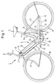
- FIG. 1 is a side elevational view of an electric power assisted bicycle according to the present invention.
- FIG. 2 is a vertical sectional view of a battery case.
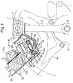
- FIG. 3 is a vertical sectional side elevational view of a rear portion of a battery case assembly and a bottom portion of a center case.
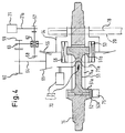
- FIG. 4 is a schematic structural view of a transmission gear mechanism and treadling force detection means.
- FIG. 5 is a functional block constructive view of a control apparatus of the electric power assisted bicycle according to the present invention.
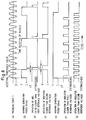
- FIG. 6 is a time chart illustrating examples of operation of assisting force variation means.
- FIG. 7 is a time chart illustrating other examples of operation of the assisting force variation means.
- FIG. 8 is a time chart illustrating examples of operation of indication control means.
- FIG. 9 is a circuit constructive view showing a detailed example of the control apparatus.
- FIG. 10 is a time chart illustrating operation of motor driving limiting means.
- FIG. 11 is a flow chart illustrating general operation of the control apparatus.
- FIG. 1 is a side elevational view of an electric power assisted bicycle according to the present invention.
- a down tube 3 extends in an oblique rearward downward direction from a head pipe 2 of the electric power assisted bicycle 1 and is curved upwardly at a lower end of the down tube 3 such that a seat tube 4 extends in an oblique rearward upward direction, and a main frame 5 of a substantially V-shaped configuration is constituted from the down tube 3 and the seat tube 4.
- a seat 6 is provided at an upper end of the seat tube 4.
- a steering shaft 7 is fitted for rotation in the head pipe 2, and a steering handlebar 8 is mounted integrally at an upper end of the steering shaft 7 while a front wheel 10 is supported for rotation at lower ends of a pair of left and right front forks 9 which extend integrally downwardly from the Steering shaft 7.
- a bracket 5a (refer to FIG. 3) is provided projectingly at a lower portion of the curved portion of the main frame 5 at which the down tube 3 and the seat tube 4 cross each other, and a transmission gear mechanism is accommodated in the bracket 5a while a gear box 11 which serves also as a crankcase is mounted integrally on the bracket 5a.
- a rear fork 12 directed in the forward and rearward direction is integrally mounted at a front end thereof on the gear box 11, and a stay 13 is mounted on the seat tube 4 and a rear end of the rear fork 12 while a rear wheel 14 is supported for rotation at the rear end of the rear fork 12.
- a crankshaft 15 is mounted for rotation on the gear box 11, and a pair of crank arms 16 are integrally mounted at the opposite left and right ends of the crankshaft 15.
- a pedal 17 is mounted at an end of each of the crank arms 16.
- An endless chain 20 extends between and around a driving sprocket wheel 18 integrally provided on the crankshaft 15 and a driven sprocket wheel 19 integrally provided on the rear wheel 14 such that, when the crankshaft 15 is driven to rotate by the treadling force applied to the pedals 17, the rear wheel 14 is rotated by way of the driving sprocket wheel 18, the endless chain 20 and the driven sprocket wheel 19 so that the electric power assisted bicycle 1 can run as a bicycle.
- a motor 21 is secured to the gear box 11 along the seat tube 4, and a control apparatus 22 including an electronic control unit, a motor driver and so forth for controlling rotation of the motor 21 is provided at a position on a rear side fade of the seat tube 4 above the motor 21.
- a control apparatus 22 including an electronic control unit, a motor driver and so forth for controlling rotation of the motor 21 is provided at a position on a rear side fade of the seat tube 4 above the motor 21.
- the main frame 5 constituted from the down tube 3 and the seat tube 4 is covered with a side cover 23, which is split into two left and right portions, and a center cover 24 which are arranged in a substantially V-shaped configuration, and an elongated battery case assembly 25 can be removably mounted on an inclined upper face of the side cover 23 which covers over the dowry tube 3.
- a main switch 41 formed from a key switch ( combination switch) or the like is disposed at a front end portion of the side cover 23. It is to be noted that, when the switch is operated to an on position, the battery case assembly 25 is prevented from being removed by way of a locking apparatus (not shown) which operates in response to an operation of the main switch 41.
- An indicator 42 for visibly indicating a drop of the voltage of a battery power source and that charging is required is disposed in the proximity of the main switch 41.
- connection portion 43 for connection with a charging connector or the like is provided on a side face of the battery case assembly 25 so that charging can be performed even in a condition wherein the battery case assembly 25 is mounted on the electric power assisted bicycle 1.
- the indicator 42 may otherwise be provided on the battery case assembly 25 side.
- the connector structure may be such that the battery case assembly 25 can be connected to the indicator 42 by mounting the battery case assembly 25 onto the indicator 42.
- the indicator 42 and a charging control circuit on the charger side may be electrically connected to each other while a charging condition is indicated using the indicator 42 mounted on the battery case assembly 25.
- FIG. 2 is a vertical sectional view of the battery case.
- the battery case assembly 25 is divided into two upper and lower portions of a lower case 26 and an upper case 27, and a power source battery set 29 including 20 cylindrical D-size Ni-Cd (nickel-cadmium) batteries 28a and 28b is removably fitted in the battery case assembly 25.
- a power source battery set 29 including 20 cylindrical D-size Ni-Cd (nickel-cadmium) batteries 28a and 28b is removably fitted in the battery case assembly 25.
- the upper case 27 of the battery case assembly 25 constitutes part of an outer surface of a body of the electric power assisted bicycle 1.
- the power source battery set 29 is constructed in such a manner as described below. While the 10 Ni-Cd batteries 28a are arranged in a row in a direction perpendicular to the center lines of the Ni-Cd batteries 28a in a condition wherein the positive and negative poles are positioned alternately between each adjacent Ni-Cd batteries 28a and circumferential faces of the Ni-Cd batteries 28a are held in contact with each other, the Ni-Cd batteries 28b in the upper layer are placed such that the upper Ni-Cd batteries 28b may be received in upper recessed portions of the row of the Ni-Cd batteries 28a in the lower layer. As indicated by broken lines in FIG.
- connection pieces 30a are connected by soldering to the positive and negative poles of the adjacent Ni-Cd batteries 28a in the lower layer, and also the Ni-Cd batteries 28b in the upper layer are connected to each other similarly using connection pieces 30b.
- connection piece 30c the positive and negative poles are connected to each other by a connection piece 30c, and then, the upper and lower Ni-Cd batteries 28a and 28b are inserted into a tubular heat contractive synthetic resin film 31, whereafter the heat contractive synthetic resin film 31 is heated to contract itself.
- a pair of leads 33a and 33b are integrally connected at one ends thereof by soldering to terminal pieces 32a and 32b connected to the negative pole and the positive pole of the Ni-Cd battery 28a at the rear end (right end in FIG. 2) and the Ni-Cd battery 28b at the rear end.
- the other ends of the leads 33a and 33b are connected to a feeding connector 34 (details are shown in FIG. 3) so that power may be supplied to the control apparatus 22 side by way of the feeding connector 34.
- a heat sensitive resistance element 35 such as a thermistor is disposed between the Ni-Cd batteries 28a and 28b of the upper and lower layers.
- the heat sensitive resistance element 35 is connected to a charging connector 36 shown in FIG. 3 by way of a lead 35a so that, when charging is performed using the charger not shown, the charger side not shown can supervise the temperature of the location of the Ni-Cd batteries 28a and 28b from the resistance value of the heat sensitive resistance element 35.
- various fuses 37 and circuit parts such as a diode (not shown) for preventing a charging voltage of a reverse polarity from being supplied are mounted in the battery case assembly 25.
- FIG. 3 is a vertical sectional side elevational view of a rear portion of the battery case assembly and a bottom portion of the center case.
- a feeding connector 38 is disposed at a rear end portion of the battery case assembly 25.
- the feeding connector 38 includes a pair of left and right contact terminals 38a each made of a conductive elastic material such as a copper alloy plate.
- Each of the contact terminals 38a is secured, at an end portion thereof, to the connector case using a screw 40 and is electrically connected to the lead 33a or 33b.
- a connector 39 which makes a counterpart of the feeding connector 38 is disposed on a bottom wall 24a of the center cover 24.
- the connector 39 has a pair of left and right bar-like projecting terminals 39a.
- the projecting terminals 39a extend through openings 26a formed in the lower case 26 and openings 38b of the feeding connector 38 until ends thereof are contacted with the contact terminals 38a.
- the power of the battery power source is supplied by way of them.
- each of the contact terminals 38a is pushed up and displaced by the contact terminal 38a, and a coil spring 38c is provided at the displacement portion to obtain a sufficient contacting pressure and to make occurrence of momentary disconnection of supply of the power by driving oscillations or the like difficult.
- FIG. 4 is a schematic structural view of the transmission gear mechanism and treadling force detection means.
- a through-hole 15a is formed in an intermediate portion of the crankshaft 15 in its axial direction such that it extends through the crankshaft 15 in a diametrical direction and extends in the axial direction.
- a torsion bar 51 accommodated coaxially with the crankshaft 15 in the inside of the through-hole 15a has a head portion 51a formed at a left end (input end) thereof and coupled to the crankshaft 15 by way of a collar 52 and has a head portion 51b formed at a right end (output end) thereof and coupled to an annular driving member 53 by force fitting in a recessed groove formed on an inner periphery of the driving member 53.
- a pair of wall faces of the through-hole 15a of the crankshaft 15 which are opposed to each other are curved substantially arcuately thereby to allow relative rotation of the crankshaft 15 over a predetermined angle around the head portion 51b on the free end side of the torsion bar 51 and prevent break of the torsion bar 51 when an excessively high load acts upon the same.
- a first one-way clutch 56 is provided between a bevel gear 55 securely mounted on the inner periphery of a sleeve 54 and the annular driving member 53. If the pedals 17 not shown are treadled to rotate the crankshaft 15 forwardly, the torque of the crankshaft 15 is transmitted by way of the torsion bar 51, the driving member 53, the bevel gear 55 and the sleeve 54 to the driving sprocket wheel 18 spline coupled to the outer periphery of the sleeve 54 and is then transmitted to the rear wheel 14 by way of the endless chain 20 and the driven sprocket wheel 19 shown in FIG. 1. On the other hand, if the pedals 17 not shown are treadled to rotate the crankshaft 15 reversely, the first one-way clutch 56 will slip to allow the reverse rotation of the crankshaft 15.
- a second one-way clutch 62 is provided for a first intermediate shaft 63. It is to be noted that reference numeral 64 denotes a second intermediate shaft.
- Treadling force detection means 70 is constituted from torque-displacement conversion means 71 for converting a twist by a treadling force (torque) into a displacement in an axial direction, and a stroke sensor 72 for outputting an electric signal corresponding to the displacement.
- the torque-displacement conversion means 71 is constituted from a convex cam face formed on an end face of a slider inner member 71a which rotates integrally with the crankshaft 15 and a concave came face formed on an end face of the driving member 53 and engaged with the convex cam face.
- a toothed portion 52a is formed on an outer periphery of the collar 52 for coupling the crankshaft 15 and the head portion 51a of the torsion bar 51 to each other, and a crankshaft rotational speed sensor 75 is disposed in an opposing relationship to the toothed portion.
- the crankshaft rotational speed sensor 75 is constructed such that it optically or magnetically detects the toothed portion 52a and outputs a detection pulse.
- FIG. 5 is a functional block constructive view of the control apparatus of the electric power assisted bicycle according to the present invention.
- the control apparatus 22 includes motor operation control means 100, assisting force variation type warning means 110 and indication control means 120.
- the motor operation control means 100 includes crank rotational speed calculation means 101, an A/D converter 102, assisting force calculation means 103 and PWM signal production means 104.
- crank rotational speed calculation means 101 outputs data (hereinafter referred to as crank rotational speed) V regarding the crank rotational speed in response to a pulse signal 75a regarding the crank rotational speed detected by the crankshaft rotational speed sensor 75.
- a voltage signal 70a regarding the treadling force outputted from the treadling force detection means 70 is converted into a digital signal (hereinafter referred to as treadling force) T corresponding to the treadling force by the A/D converter 102.
- the assisting force calculation means 103 calculates, from the treadling force T and the crank rotational speed V, an assisting force in accordance with an operation expression set in advance or by reference to a conversion table registered in advance, and outputs assisting force data 103a.
- the PWM signal production means 104 produces and outputs, from assisting force data A or variation assisting force data HA supplied thereto by way of the assisting force variation type warning means 110, a PWM signal 104a necessary to supply an assisting force from the motor 21.
- the PWM signal 104a is supplied to the gate of a field effect transistor FET by way of a gate driving circuit or the like not shown so that PWM driving of the motor 21 is performed.
- reference character B denotes the battery power source
- reference character SW denotes feed switching means for contacts or the like of the main switch or a relay which operates in response to the main switch.
- the assisting force variation type warning means 110 includes assisting force variation control means 111 and voltage drop detection means 112.
- the voltage drop detection means 112 includes an A/D converter 113, power source voltage supervision means 114 and reference voltage setting means 115.
- the power source voltage of the battery power source B is divided into a voltage within an allowable input voltage range of the A/D converter 113 by resistors RA and RB in a resistor voltage divider 116, and the thus divided battery power source voltage is supplied to the A/D converter 113 to obtain digital voltage data 113a.
- the reference voltage setting means 115 is provided to set a voltage at which a warning of a drop of the battery capacity is to be generated, and in the present embodiment, it sets two different voltages.
- a first reference voltage VTH1 is set in order to notify that the remaining capacity of the battery has reduced small and charging is required, and for example, it is set to 22 volts with respect to 24 volts of a rated output voltage of the battery power source B.
- a second reference voltage VTH2 is set to a voltage at which the remaining capacity of the battery is almost exhausted or a voltage for preventing the battery from entering an over discharge condition, for example, to 20 volts.
- the reference voltage setting means 115 can be constituted from a ROM in which reference voltage data set in advance are stored or a digital switch or the like.
- control apparatus 22 is constructed so as to operate with a low voltage (for example, 5 volts) supplied thereto by way of a stabilized power source (not shown) of the step-down type, and is constructed so as to operate even when the battery voltage drops below the second references value.
- a low voltage for example, 5 volts
- the power source voltage supervision means 114 includes voltage data temporary storage means such as a RAM or a memory of the FIFO type for temporarily storing digital voltage data 113a obtained by A/D conversion at predetermined time intervals, and calculates an average value of a plurality of time series data (for example, 5 data) to obtain a short time average voltage of the battery power source B. Further, the power source voltage supervision means 114 compares the short time average voltage with the reference voltages VTH1 and VTH2, and outputs a first voltage drop detection signal 114a when it detects that the power source voltage of the battery power source B has dropped below the first reference voltage VTH1, but outputs a second voltage drop detection signal 114b when the battery voltage has further reduced until it becomes lower than the second reference voltage.
- voltage data temporary storage means such as a RAM or a memory of the FIFO type for temporarily storing digital voltage data 113a obtained by A/D conversion at predetermined time intervals, and calculates an average value of a plurality of time series data (for example, 5 data) to
- the assisting force variation control means 111 supplies, when the voltage drop detection signal 114a or 114b is not supplied thereto, assisting force data A outputted from the assisting force calculation means 103 as they are to the PWM signal production means 104, but when the first voltage drop detection signal 114a or 114b is supplied thereto, the assisting force variation control means 111 changes part of the assisting force data A and supplies the thus changed variation assisting force data HA to the PWM signal production means 104. Further, while changing of the assisting force data A is being performed, the assisting force variation control means 111 supplies to the indication control means 120 warning generation period signal 111a which indicates that a physical feeling warning is being generated.
- the indication control means 120 includes indication manner control means 121 for generating and outputting an indicator driving signal 121a in response to the voltage drop detection signal 114a or 114b and the warning generation period signal 111a, and indication manner storage means 122 formed from a ROM or the like in which data regarding various indication manners set in advance are stored.
- the indicator driving signal 121a is supplied to an indicator driving circuit 123, and lighting of the indicator 42 constituted making use of, for example, a lamp or a light emitting diode is performed by way of the indicator driving circuit 123.
- the indicator 42 may be of the type which displays a histogram (pictograph) of a battery or characters of charge or the like.
- FIG. 6 is a time chart illustrating examples of operation of the assisting force variation means.
- the examples of operation illustrated in FIG. 6 are constructed such that both of the degree of reduction of the assisting force and the distance at which reduction is performed are varied in response to the degree of the drop of the voltage of the battery power source.
- FIG. 6 illustrates the variation of the treadling force T.
- the treadling force is zero at the top dead center and the bottom dead center from the structure of the bicycle. It is to be noted that, in this figure, the case wherein the pedals are treadled at a fixed speed with a fixed force is illustrated. Since the assisting force calculation means 103 is constructed such that it calculates and outputs an assisting force when the treadling force T exceeds an assisting threshold value, an assisting force A illustrated in (b) of FIG. 6 is outputted.
- the assisting force variation control means 111 When the power source voltage of the battery power source B becomes lower than the first reference voltage VTH1 (for example, 22 volts) and a first voltage drop detection signal 114a is supplied, the assisting force variation control means 111 outputs variation assisting data HA obtained by multiplying the assisting force data A by a predetermined first coefficient (for example, 0.6 to 0.8) lower than 1.
- a predetermined first coefficient for example, 0.6 to 0.8
- the assisting force variation control means 111 outputs variation assist data HA obtained by multiplying the assisting force data A by another coefficient (for example, 0.2) further lower than the first coefficient every five rotations of the pedals as seen from (e) of FIG. 6, and outputs a warning generation period signal 111a corresponding to this as seen from (f) of FIG. 6.
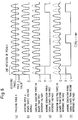
- FIG. 7 is a time chart illustrating different examples of operation of the assisting force variation means.
- the waveforms shown in (g) and (i) of FIG. 7 are obtained by fixing the degree of reduction of the assisting force and varying the interval at which reduction is performed.
- (g) of FIG. 7 shows the waveform in a case wherein, when the power source voltage becomes lower than the first reference voltage VTH1 (for example, 22 volts), the assisting force is reduced approximately half and this is continued for two rotations of the pedals.
- (h) of FIG. 7 shows the waveform in a case wherein, when the power source voltage becomes lower than the second reference voltage VTH2 (for example, 20 volts), the assisting force is reduced approximately half similarly as in (g) of FIG. 7 and this is continued for 5 rotations of the pedals.
- the battery power source voltage may vary in response to a current value to be supplied. And, it is assumed that, if a high assisting force is requested and the current to the motor 21 becomes high, the battery power source voltage drops below a reference voltage, and then when the motor current decreases, the battery power source voltage returns above the reference voltage, then a voltage drop detection signal is outputted and then stopped, and if the assisting force is varied in response to such voltage drop detection signal, then there is the possibility that an inadvertent reactive force may act upon a foot treadling a pedal.
- the power source voltage supervision means 114 is constructed such that, after it outputs a voltage drop detection signal, it stops outputting of the voltage drop detection signal at a point of time when the condition wherein the power source voltage is higher than a reference value continues for a predetermined period of time. Further, the assisting force variation control means 111 does not vary the assisting force immediately at a point of time when a voltage drop detection signal is supplied thereto, but thereafter confirms that the assisting force data A have changed to zero and varies the assisting force in synchronism with a next pedal rotating cycle. Accordingly, such a situation that the pedal becomes heavy suddenly and an unexpected reactive force acts upon a foot or the assisting force reduction condition is canceled suddenly and it is felt that a foot slips does not occur.
- FIG. 7 shows the waveforms in a case wherein the assisting force is varied moderately over several rotations of the pedals.
- (i) of FIG. 7 shows the waveform in a case wherein, when the power source voltage becomes lower than the first reference voltage VTH1 (for example, 22 volts), the assisting force is first decreased for every rotation of the pedals and then restored.
- (j) of FIG. 7 shows the waveform in another case wherein the assisting force is reduced for every rotation of the pedals until it becomes equal to zero and is then restored gradually.
- the processing of stopping the assisting operation first for a predetermined time (for example, 10 seconds) and performing the assisting operation for a predetermined time (for example, for several tens seconds), whereafter the assisting operation is stopped, may be performed several times (for example, four times), and thereafter, the assisting operation may be stopped completely to reduce consumption of the battery power source.
- FIG. 8 is a time chart illustrating examples of operation of the indication control means.
- FIG. 8 illustrate the waveforms in a case where wherein the indicator 42 is lit for a predetermined time in synchronism with a falling edge of a warning generation period signal 111a.
- the warning generation period signal 111a continues for a comparatively short period of time such as a period within which the pedals are rotated once, if it is intended to light the indicator 42 in synchronism with a falling edge of the warning generation period signal 111a, then the indication manner is such that, after the driver feels a variation of the assisting force and confirms the indicator 42, the indicator 42 is extinguished after it is lit. Since the indication condition varies, it is easier to visually discern it than another case wherein the indicator 42 is lit continuously. It is to be noted that the lighting timing of the indicator 42 may be synchronized with a rising edge of the warning generation period signal 111a or the indicator 42 may be lit after lapse of a predetermined time after a rising edge.
- the indicator 42 may be lit for a short time t1 (for example, 0.5 seconds) when the voltage of the battery power source is lower than the first reference value whereas, when the voltage of the battery power source is further lower than the second reference value, the indicator 42 is lit for a longer time t2 (for example, about 1 second) so that the remaining capacity of the battery can be visually discerned from the length of the lit time.
- a short time t1 for example, 0.5 seconds
- t2 for example, about 1 second
- the duration ratio may be varied to vary the brightness of the indication so that the remaining capacity of the battery may be discerned.
- lighting/extinction may be repeated as seen from (f) and (g) of FIG. 8.
- the lighting interval may be varied in response to the voltage of the battery power source, or even if the lighting interval is equal, the rate between the lighting time and the extinction time may be varied so that the degree of the remaining capacity may be discerned.
- FIG. 5 shows the construction wherein, when the battery power source voltage exhibits a drop after the assisting force A is calculated, the calculated assisting force is varied to vary the assisting force
- the assisting force may be varied by changing the treadling force T to be supplied to the assisting force calculation means 103.
- the assisting force calculation means 103 includes an assisting force retrieval table for a case wherein the power source voltage is normal and assisting force retrieval tables for another case wherein the power source voltage is lower than the first reference voltage and a further case wherein the power source voltage is lower than the second reference voltage
- the assisting force may be varied by changing over a table to be used in response to the voltage supervision output of the power source voltage supervision means 114.
- the assisting force may be varied as a construction for varying the duty of a PWM signal in response to the voltage supervision output.
- the assisting force may be varied or the indication manner may be varied in response to each degree of the drop.
- FIG. 9 is a circuit constructive view showing a detailed example of the control apparatus.
- a battery power source BAT in the battery case assembly 25 is applied by way of a feeding side fuse FO from terminals B+ and B- of the feeding connector 38 to power source terminals B+ and B- of a control apparatus 200. It is to be noted that charging is performed from a positive pole side terminal 36a of the charging connector 36 by way of a diode DI and a charging side fuse FI.
- the heat sensitive resistance element 35 for detecting the battery temperature upon charging is connected at a terminal thereof to a negative pole side terminal 36b and at the other terminal to a signal terminal 36c.
- the battery power source BAT is supplied from a positive pole side power source terminal VB of the control apparatus 200 to a power source/resetting circuit section 201 by way of the feeding side fuse FO, the main switch 41 and a terminal SW, and charging of a capacitor C1 for stabilizing the motor power source is performed by way of a pre-charging circuit 202 constituted from a diode D1 and a charge current limiting resistor R1.
- the power source/resetting circuit section 201 includes a 12 V system and 5 V system power source 201a for stepping down the battery power source of, for example, a 24 V system and outputting stabilized power sources of a 12 V system and a 5 V system, and a resetting circuit 201b which operates with the 5 V system power source.
- the 12 V system power source is used for the crankshaft rotational speed sensor 75 and as a gate controlling voltage for the field effect transistor FET for power for controlling energization of the motor 21.
- the 5 V system power source is used by a one-chip microcomputer 203, motor driving limitation means 210, a motor current detection circuit 204 and so forth.
- the resetting circuit 201b supplies a reset pulse RS to a CPU upon first transition of the 5 V system power source and supervises a watchdog pulse WP outputted in a predetermined cycle from the CPU 203a.
- the resetting circuit 201b outputs a reset pulse RS to reset (initialize) the CPU. Further, if supply of a watchdog pulse WP is not resumed also after a reset pulse RS is outputted, the resetting circuit 201b supplies a cutoff instruction POFF to the 12 V system and 5 V system power source 201a to stop supply of the 12 V and 5 V power sources.
- the motor operation control means 100, the assisting force variation type warning means 110, the indication control means 120 and so forth shown in FIG. 5 are constituted using the one-chip microcomputer 203 in which the CPU 203a, a ROM/RAM 203b, an A/D converter 203c, a timer 203T of a plurality of systems and so forth are built.
- a voltage across the capacitor C1 for stabilizing the motor power source is divided by a resistor R2 and another resistor R3 so that it may fall within an allowable input voltage range of the A/D converter 203c, and the thus divided voltage is supplied to an input terminal A5 of the A/D converter 203c.
- the CPU 203a outputs, after initialization processing performed in response to a reset pulse RS, a relay driving instruction 203d at a point of time when the divided voltage value after A/D conversion exceeds a preset voltage. Consequently, an exciting winding of a relay 206 is energized by way of a relay driving circuit 205 to put the contacts of the relay 206 into a closed condition so that the battery power source BAT is applied to the motor 21.
- the voltage across the capacitor C1 is a voltage equal to the battery voltage divided by the charge current limiting resistor R1 and the resistance of the winding of the motor 21.
- the resistance value of the charge current limiting resistor R1 is set sufficiently higher than the resistance value of the winding of the motor 21.
- the CPU 203a supervises the voltage across the capacitor C1 even when the motor 21 is in an operating condition, and performs correction of the energization ratio of a PWM signal 203e so that a desired assisting torque may be obtained in response to an actual voltage value applied to the motor 21. Consequently, even when the battery power source voltage drops or the like, a desired assisting torque can be generated.
- a surge voltage of the reverse polarity which is produced when energization of the motor 21 is stopped is absorbed by the battery power source BAT by way of a diode D3.
- a fuse for a high current severe tens amperes
- the current resisting amount of the main switch 41 may be small and a fuse F1 connected in series to the main switch 41 may be constructed for a small capacity (several amperes).
- the 12 V system power source is supplied to the crankshaft rotational speed sensor 75 by way of a bleed resistor R4. Even if a short-circuiting failure or the like occurs on the crankshaft rotational speed sensor 75 side with respect to a terminal VC, since the short-circuit current is limited by the bleed resistor R4, the power source circuit is protected.
- a crank rotational speed detection signal 75a supplied to a terminal CP is waveform shaped by a waveform shaping circuit 209 and converted into a signal of the logic amplitude of the 5 V system, which is supplied to the input terminal of the CPU 203a.
- the 5 V system power source is supplied to the treadling force detection means 70 by way of a bleed resistor R5. Even if a short-circuiting failure or the like occurs on the treadling force detection means 70 side with respect to a terminal VT, since the short-circuit current is limited by the bleed resistor R5, the power source circuit is protected.
- a treadling force detection output (voltage signal) 70a supplied to a terminal TS is divided by a pair of sets of voltage dividing circuits having different voltage dividing ratios, and the thus divided voltages are supplied to the A/D converter 203c.
- the voltage dividing ratio of one of the voltage dividing circuits which is constituted from a resistor R6 and another resistor R7 is set, for example, to 1/2, and the voltage dividing ratio of the other voltage dividing circuit which is constituted from a resistor R8 and another resistor R9 is set, for example, to 1/4.
- a pair of systems of detection voltages having different voltage dividing ratios are prepared, and the CPU 203a detects the magnitude of a detection torque based on A/D conversion data of the two systems, and selects, when the detection torque is low, D/A conversion data of the voltage (voltage dividing ratio 1/2) supplied to an A/D input terminal A2, but selects, when the torque is high, D/A conversion data of the voltage (voltage dividing ratio 1/4) supplied to another A/D input terminal A3, to convert a torque taking the voltage dividing ratio into consideration. Due to such construction and processing, even if the resolution of the A/D converter 203c is equal, a torque value with a high degree of accuracy can be detected over a wide range from a low torque to a high torque.
- the detection output of the treadling force detection means 70 is influenced by the power source voltage supplied thereto, the voltage being actually supplied to the treadling force detection means 70 is supplied to the A/D input terminal A1, and the detection voltage is corrected based on D/A conversion data of the voltage in order to detect a treadling force with a high degree of accuracy.
- a voltage comparator 212 in the motor driving limitation means 210 is constructed so as to compare a threshold value voltage VTH obtained by dividing the voltage being supplied to the treadling force detection means 70 by means of a resistor 211a and another resistor 211b with the voltage obtained by dividing the treadling force detection output 70a by means of the resistor R8 and the resistor R9. Since the voltage being supplied to the treadling force detection means 70 is divided to obtain the threshold value voltage VTH, it can be determined with a higher degree of accuracy whether or not the treadling force exceeds a predetermined value.
- An output 212a of the voltage comparator 212 is supplied to an input terminal of the CPU 203a.
- the CPU 203a supervises that the condition wherein the output 212a of the voltage comparator 212 is at an L level, that is, the treadling force is zero, occurs cyclically. And, if the condition wherein the treadling force is zero is not detected cyclically in a condition wherein the motor 21 is operating based on detection of a treadling force based on A/D conversion data, outputting of the PWM signal 203e is stopped to stop operation of the motor 21. By this, it is prevented that operation of the treadling force detection system such as the treadling force detection means 70 and the A/D converter 203c is not normal and an unnecessary assisting torque is generated.
- the CPU 203a retrieves a PWM duty map based on a treadling force detected by way of the A/D converter 203c and a pulse signal 75a corresponding to the crank rotary shaft rotational speed and produces and outputs a PWM signal 203e corresponding to the thus found duty.
- the PWM signal 203e is supplied by way of a logical AND circuit 213 to a FET driving circuit 207 while the output 212a of the voltage comparator 212 remains at a H level, that is, while a treadling force higher than a predetermined value is being detected.
- the FET driving circuit 207 supplies electric power to the field effect transistor FET in response to a logical AND output signal 213a to drive the field effect transistor FET to perform a switching operation. Consequently, the motor 21 is driven under PWM control.
- the CPU 203a supervises the motor current to check whether or not the driving operation of the motor 21 is proceeding normally, and limits operation of the motor 21 when it detects an abnormal current value.
- Detection of the motor current is based on data obtained by A/D conversion of a voltage, which corresponds to a motor current and is produced between the opposite ends of the current detection resistor 204 interposed between the source of the field effect transistor FET and the negative pole of the battery power source BAT, supplied to an A/D conversion input terminal A5 of the A/D converter 203c.
- the CPU 203a is constructed so as to suppress the energization duty low or stop operation of the motor 21 when the motor current value is excessively high based on voltage data according to the motor current value after A/D conversion.
- the A/D converter 203c starts counting of the timer 203T at a point of time when the voltage data according to the motor current value after A/D conversion exceeds a preset value at which the motor current substantially corresponds to zero or is near to zero, and when the motor current does not become lower than the value substantially corresponding to zero within an allowable time set in advance, the one-chip microcomputer 203 stops outputting of the relay driving instruction 203d to stop feeding to the motor 21. Accordingly, even if the operation of the treadling force detection system is no more normal and the treadling force does not return to zero, an unnecessary assisting force will not continue to be supplied.
- the CPU 203a compares the data regarding the battery power source voltage fetched thereto by way of the A/D converter 203c with the first and second reference voltages VTH1 and VTH2 set in advance, and when the battery power source voltage is lower than the first reference voltage VTH1, the CPU 203a first decreases the assisting force moderately and then restores the assisting force moderately, for example, as seen from (k) of FIG. 7, in order to appeal to the physical feeling of the driver and notify that the battery power source voltage is in a dropped condition. Further, the CPU 203a causes the indicator 42 to be lit for a predetermined short period of time by way of the lamp driving circuit 208 to indicate that the remaining capacity of the battery is small and a charging time has come.
- the battery power source voltage has dropped lower than the second reference voltage VTH2
- supplying of the assisting force is stopped, for example, for 10 seconds, and then assisting is performed again.
- blinking indication wherein the indicator 42 is, for example, lit for 0.5 seconds and extinguished for 0.5 seconds is repeated.
- the relay 206 is controlled into an off-state to completely stop energization of the motor 21 while the indicator driving signal 121a is continued to be outputted to continuously light the indicator 42.
- FIG. 10 is a time chart illustrating operation of the motor driving limiting means.
- the treadling force detection output 70a exhibits a voltage waveform which repeats a cyclic increase and decrease as shown in (a) of FIG. 10.
- the voltage comparator 212 outputs a signal 212a of a H level as seen from (c) of FIG. 10 while the voltage of the treadling force detection output 70a exceeds the threshold value voltage VTH. Accordingly, when the PWM signal 203e shown in (b) of FIG. 10 is produced and outputted from the CPU 203a in response to the voltage signal 70a, a logical AND output signal 213a shown in (d) of FIG.
- FIG. 11 is a flow chart illustrating general operation of the control apparatus.
- the CPU 203a determines at step S1 whether or not pre-charging of the capacitor C1 for stabilizing the motor power source has been completed, and after completion of pre-charging, the CPU 203a outputs a relay driving instruction 203d (S2). Then, calculation of the crankshaft rotational speed (S3) and detection of the treadling force (S4) are performed, and the assisting force A is calculated (S5).
- the CPU 203a supervises the battery voltage (S6), and when the battery voltage exceeds the first reference voltage VTH1, the CPU 203a produces and outputs, at step S12, a PWM signal necessary to supply the assisting force A to perform PWM operation of the motor 21.
- the CPU 203a varies the assisting force A at step S7 and causes the indicator 42 to be lit for a predetermined time at step S8.
- the CPU 203a varies the assisting force to zero or a low value at step S9 and performs blinking control of the indicator 42 at step S10.
- the CPU 203a counts the number of times by which the assisting force has been varied to zero or the low value, and if the number of repetitions reaches, for example, five times, the CPU 203a performs assisting complete stopping processing at following steps beginning with step S16.
- a PWM signal is produced and outputted in accordance with the assisting force or the varied assisting force. Then, at step S13, a current actually flowing through the motor is detected, and it is checked at step S14 whether or not the motor current exceeds a reference value. If the time within which the motor current exceeds the reference value is supervised and reaches an allowable time at step S15, the CPU 203a stops outputting of the PWM signal (S16) and stops outputting of the relay driving instruction 203d to stop feeding to the motor 21 (S17).
- the assisting force variation type warning means detects a drop of the voltage of the battery power source, then it intentionally varies the driving condition of the motor to vary the assisting force, the assisting force to be supplied from the motor is varied.
- the driver can physically feel that the capacity of the battery power source has reduced small. Consequently, even if no attention is paid to an indication of an indicator or the like, the driver can get aware of it rapidly at a point of time when the voltage drops that the remaining capacity of the battery has become small.
- the driver can perceive the remaining capacity of the battery such that, for example, since the feeling in treadling the pedals has become a little heavy, charging is required early or since the feeling in treadling the pedals is considerably heavy, the battery may be exhausted soon.
- the indication of the indicator is caused to blinks in association with the variation of the assisting force, it can be confirmed from the blinking of the indication that the variation in driving feeling originates from a reduction of the remaining capacity of the battery power source. If the driver physically feels the variation in assisting force and carefully observes the indication section or the like, then since the indicator of a battery remaining capacity warning lamp or a warning lamp which indicates that charging is required is blinking, it can be recognized readily that the variation of the assisting force is originated from the reduction of the battery capacity.
- the blinking manner of the indication of the indicator is varied in response to the degree of the drop of the voltage of the battery power source, such remaining capacity of the battery that the battery may be exhausted soon can be visibly indicated in such a manner that, for example, the blinking interval of the indicator is reduced or the rate of the time within which the indicator is lit becomes higher than the rate of the time within which the indicator is extinguished.
- the present invention causes when the capacity of a secondary battery for generation of an assisting force (assisting force) drops (the voltage drops), a driver to physically feel it as a variation in driving feeling that the remaining capacity has reduced and charging is required by intentionally varying the assisting force to assist driving by human power.
- a voltage drop detection means 112 compares data 113a obtained by A/D conversion of the voltage of a battery B with reference voltages VTH1 and VTH2 set in advance and outputs voltage drop detection signals 114a and 114b.
- assisting force variation control means 111 outputs a variation assisting force HA obtained by reducing or varying an assisting force A calculated by assisting force calculation means 103 almost to zero.
- PWM signal production means 104 produces and outputs a PWM signal 104a in response to the assisting force A or the variation assisting force HA to drive a motor 21 by PWM driving.
Landscapes
- Engineering & Computer Science (AREA)
- Transportation (AREA)
- Mechanical Engineering (AREA)
- Chemical & Material Sciences (AREA)
- Combustion & Propulsion (AREA)
- Life Sciences & Earth Sciences (AREA)
- Sustainable Development (AREA)
- Sustainable Energy (AREA)
- Power Engineering (AREA)
- Electric Propulsion And Braking For Vehicles (AREA)
- Charge And Discharge Circuits For Batteries Or The Like (AREA)
Applications Claiming Priority (2)
| Application Number | Priority Date | Filing Date | Title |
|---|---|---|---|
| JP19444794A JP3276782B2 (ja) | 1994-08-18 | 1994-08-18 | 電動補助自転車 |
| JP194447/94 | 1994-08-18 |
Publications (2)
| Publication Number | Publication Date |
|---|---|
| EP0697331A1 true EP0697331A1 (fr) | 1996-02-21 |
| EP0697331B1 EP0697331B1 (fr) | 1997-11-12 |
Family
ID=16324728
Family Applications (1)
| Application Number | Title | Priority Date | Filing Date |
|---|---|---|---|
| EP95112327A Expired - Lifetime EP0697331B1 (fr) | 1994-08-18 | 1995-08-04 | Bicyclette assistée par un moteur électrique |
Country Status (7)
| Country | Link |
|---|---|
| US (1) | US5806621A (fr) |
| EP (1) | EP0697331B1 (fr) |
| JP (1) | JP3276782B2 (fr) |
| CN (1) | CN1055442C (fr) |
| DE (1) | DE69501022T2 (fr) |
| ES (1) | ES2111996T3 (fr) |
| TW (1) | TW276230B (fr) |
Cited By (6)
| Publication number | Priority date | Publication date | Assignee | Title |
|---|---|---|---|---|
| DE19728253A1 (de) * | 1996-07-04 | 1998-01-15 | Matsushita Electric Ind Co Ltd | Fahrrad mit elektrischem Hilfsantrieb |
| EP0794113B1 (fr) * | 1996-03-08 | 2004-06-02 | Honda Giken Kogyo Kabushiki Kaisha | Batterie pour bicyclette à moteur auxiliaire |
| FR2891801A1 (fr) * | 2005-10-10 | 2007-04-13 | Jjg Partenaires Eurl Sarl | Velo electrique |
| CN102442396A (zh) * | 2010-09-30 | 2012-05-09 | 本田技研工业株式会社 | 电动助力自行车的控制装置 |
| CN102442398A (zh) * | 2010-09-30 | 2012-05-09 | 本田技研工业株式会社 | 电动助力自行车的控制装置 |
| EP2918490A1 (fr) * | 2014-03-14 | 2015-09-16 | Yamaha Hatsudoki Kabushiki Kaisha | Vélo à assistance électrique |
Families Citing this family (35)
| Publication number | Priority date | Publication date | Assignee | Title |
|---|---|---|---|---|
| US5758735A (en) * | 1996-07-26 | 1998-06-02 | Aerovironment, Inc. | High performance bicycle propulsion |
| US6003627A (en) * | 1996-08-08 | 1999-12-21 | Nabco Limited | Motor-driven vehicle control apparatus |
| JP3315872B2 (ja) * | 1996-08-20 | 2002-08-19 | 三洋電機株式会社 | 電動車用モータのトルク制限装置 |
| CA2246590A1 (fr) * | 1997-09-16 | 1999-03-16 | Sanyo Electric Co., Ltd. | Bicyclette a entrainement electrique |
| US6446745B1 (en) * | 2000-06-30 | 2002-09-10 | Michael John Lee | Control system for electric powered vehicle |
| DE10125828A1 (de) * | 2001-05-26 | 2002-12-05 | Bosch Gmbh Robert | Verpolschutz für Energiequellen |
| JP2004032442A (ja) * | 2002-06-26 | 2004-01-29 | Kyocera Corp | 携帯端末及びその報知方法 |
| JP2004194361A (ja) * | 2002-10-15 | 2004-07-08 | Yamaha Motor Co Ltd | 電動車両及び電動車両のマップデータ採取方法 |
| JP3793143B2 (ja) * | 2002-11-28 | 2006-07-05 | 株式会社シマノ | 自転車用電子制御装置 |
| JP3727315B2 (ja) * | 2003-04-01 | 2005-12-14 | 株式会社シマノ | 自転車用電源装置 |
| CN2820682Y (zh) * | 2005-08-12 | 2006-09-27 | 崔晓宏 | 超轻电动车 |
| KR20070021573A (ko) * | 2005-08-18 | 2007-02-23 | 삼성전자주식회사 | 모터 제어 장치, 그 제어방법 및 인버터부의 고장검출장치 |
| ATE555976T1 (de) * | 2009-03-20 | 2012-05-15 | Thoemus Veloshop Ag | Fahrradrahmen zur aufnahme einer batterieeinheit und zugehörige batterieeinheit |
| RU2520399C2 (ru) * | 2009-10-15 | 2014-06-27 | Эл И ТЕК КО., ЛТД. | Микрокомпьютер и способ его работы |
| JP5564389B2 (ja) * | 2010-09-30 | 2014-07-30 | 本田技研工業株式会社 | 電動補助自転車の制御装置 |
| JP5564390B2 (ja) * | 2010-09-30 | 2014-07-30 | 本田技研工業株式会社 | 電動補助自転車の制御装置 |
| DE102011079094A1 (de) * | 2011-01-13 | 2012-07-19 | Johannes Biechele | Fahrradrahmen, Batteriepack und Fahrrad |
| JP2012214151A (ja) * | 2011-03-31 | 2012-11-08 | Honda Motor Co Ltd | 電動補助自転車の補助力制御装置 |
| KR101366557B1 (ko) * | 2012-09-19 | 2014-02-26 | 주식회사 만도 | 전기 자전거 구동 장치 |
| JP6228442B2 (ja) * | 2012-12-14 | 2017-11-08 | ヤマハ発動機株式会社 | 駆動ユニット及び電動補助自転車 |
| JP6218172B2 (ja) * | 2012-12-17 | 2017-10-25 | ヤマハ発動機株式会社 | 駆動ユニット及び電動補助自転車 |
| JP6415809B2 (ja) * | 2012-12-17 | 2018-10-31 | ヤマハ発動機株式会社 | 駆動ユニット及び電動補助自転車 |
| JP6201366B2 (ja) * | 2013-03-27 | 2017-09-27 | 株式会社ジェイテクト | 電気負荷制御装置の過電流異常判定装置、駆動力配分制御装置、および過電流異常判定方法ならびに過電流異常判定プログラム |
| CN104097723B (zh) * | 2014-06-23 | 2017-10-03 | 苏州达方电子有限公司 | 适用于电动脚踏车的车架 |
| JP6534883B2 (ja) * | 2015-07-21 | 2019-06-26 | 株式会社シマノ | 自転車の制御装置およびこの制御装置を備える自転車のアシスト装置 |
| GB2540962A (en) | 2015-07-31 | 2017-02-08 | Nexxt E-Drive Ltd | A Method of operating a pedal cycle having an electro-mechanical drive arrangement |
| WO2017041144A1 (fr) * | 2015-09-11 | 2017-03-16 | Invertedpower Pty Ltd | Contrôleur pour charge inductive ayant un ou plusieurs enroulements inductifs |
| US9925999B2 (en) | 2015-09-29 | 2018-03-27 | Radio Flyer Inc. | Power assist wagon |
| US10583852B2 (en) | 2016-11-02 | 2020-03-10 | Radio Flyer Inc. | Foldable wagon |
| JP6802121B2 (ja) * | 2017-08-04 | 2020-12-16 | 株式会社シマノ | 自転車用コンポーネント |
| USD866676S1 (en) | 2017-11-02 | 2019-11-12 | Radio Flyer Inc. | Foldable wagon |
| JP7146385B2 (ja) * | 2017-11-15 | 2022-10-04 | 株式会社シマノ | 人力駆動車両用制御装置 |
| JP6964013B2 (ja) * | 2018-02-20 | 2021-11-10 | 株式会社シマノ | 人力駆動車の制御装置、緩衝システム、および、人力駆動車 |
| US20220212750A1 (en) * | 2019-04-25 | 2022-07-07 | Honda Motor Co., Ltd. | Electric power assist device for bicycles and bicycle |
| JP7474224B2 (ja) * | 2021-06-18 | 2024-04-24 | 株式会社ミツバ | 自動二輪車の制御装置 |
Citations (3)
| Publication number | Priority date | Publication date | Assignee | Title |
|---|---|---|---|---|
| GB2121971A (en) * | 1982-06-12 | 1984-01-04 | Lucas Ind Plc | Battery state of charge evaluator |
| US4694236A (en) * | 1985-02-26 | 1987-09-15 | Sundstrand Corporation | Control for AC motor drive |
| JPS6311420A (ja) | 1986-06-30 | 1988-01-18 | Yamaha Motor Co Ltd | 電動ゴルフカ−のバツテリ容量警告装置 |
Family Cites Families (4)
| Publication number | Priority date | Publication date | Assignee | Title |
|---|---|---|---|---|
| JPS6311402A (ja) * | 1985-05-25 | 1988-01-18 | Hideo Suzuki | タイヤのパンク防止部材 |
| DE69233024T2 (de) * | 1991-06-04 | 2003-10-16 | Yamaha Hatsudoki K.K., Iwata | Muskelgetriebenes Fahrzeug |
| JPH05105148A (ja) * | 1991-10-17 | 1993-04-27 | Yamaha Motor Co Ltd | 電動二輪車のバツテリ配置構造 |
| US5526501A (en) * | 1993-08-12 | 1996-06-11 | Hughes Aircraft Company | Variable accuracy indirect addressing scheme for SIMD multi-processors and apparatus implementing same |
-
1994
- 1994-08-18 JP JP19444794A patent/JP3276782B2/ja not_active Expired - Fee Related
-
1995
- 1995-03-07 TW TW084102138A patent/TW276230B/zh active
- 1995-06-07 US US08/476,334 patent/US5806621A/en not_active Expired - Fee Related
- 1995-06-12 CN CN95107165A patent/CN1055442C/zh not_active Expired - Fee Related
- 1995-08-04 ES ES95112327T patent/ES2111996T3/es not_active Expired - Lifetime
- 1995-08-04 EP EP95112327A patent/EP0697331B1/fr not_active Expired - Lifetime
- 1995-08-04 DE DE69501022T patent/DE69501022T2/de not_active Expired - Fee Related
Patent Citations (3)
| Publication number | Priority date | Publication date | Assignee | Title |
|---|---|---|---|---|
| GB2121971A (en) * | 1982-06-12 | 1984-01-04 | Lucas Ind Plc | Battery state of charge evaluator |
| US4694236A (en) * | 1985-02-26 | 1987-09-15 | Sundstrand Corporation | Control for AC motor drive |
| JPS6311420A (ja) | 1986-06-30 | 1988-01-18 | Yamaha Motor Co Ltd | 電動ゴルフカ−のバツテリ容量警告装置 |
Non-Patent Citations (1)
| Title |
|---|
| "yamaha's PAS power-assisted bicycle", AUTOMOTIVE ENGINEERING, vol. 101, no. 12, WARRENDALE, pages 33, XP000417563 * |
Cited By (10)
| Publication number | Priority date | Publication date | Assignee | Title |
|---|---|---|---|---|
| EP0794113B1 (fr) * | 1996-03-08 | 2004-06-02 | Honda Giken Kogyo Kabushiki Kaisha | Batterie pour bicyclette à moteur auxiliaire |
| EP1433697B1 (fr) * | 1996-03-08 | 2012-06-13 | Honda Giken Kogyo Kabushiki Kaisha | Batterie pour bicyclette à moteur auxiliaire |
| DE19728253A1 (de) * | 1996-07-04 | 1998-01-15 | Matsushita Electric Ind Co Ltd | Fahrrad mit elektrischem Hilfsantrieb |
| DE19728253C2 (de) * | 1996-07-04 | 1999-12-09 | Matsushita Electric Ind Co Ltd | Fahrrad mit elektrischem Hilfsantrieb |
| FR2891801A1 (fr) * | 2005-10-10 | 2007-04-13 | Jjg Partenaires Eurl Sarl | Velo electrique |
| CN102442396A (zh) * | 2010-09-30 | 2012-05-09 | 本田技研工业株式会社 | 电动助力自行车的控制装置 |
| CN102442398A (zh) * | 2010-09-30 | 2012-05-09 | 本田技研工业株式会社 | 电动助力自行车的控制装置 |
| CN102442396B (zh) * | 2010-09-30 | 2014-04-30 | 本田技研工业株式会社 | 电动助力自行车的控制装置 |
| CN102442398B (zh) * | 2010-09-30 | 2016-01-20 | 本田技研工业株式会社 | 电动助力自行车的控制装置 |
| EP2918490A1 (fr) * | 2014-03-14 | 2015-09-16 | Yamaha Hatsudoki Kabushiki Kaisha | Vélo à assistance électrique |
Also Published As
| Publication number | Publication date |
|---|---|
| EP0697331B1 (fr) | 1997-11-12 |
| DE69501022D1 (de) | 1997-12-18 |
| CN1055442C (zh) | 2000-08-16 |
| DE69501022T2 (de) | 1998-03-12 |
| ES2111996T3 (es) | 1998-03-16 |
| JP3276782B2 (ja) | 2002-04-22 |
| US5806621A (en) | 1998-09-15 |
| CN1129810A (zh) | 1996-08-28 |
| JPH0858667A (ja) | 1996-03-05 |
| TW276230B (fr) | 1996-05-21 |
Similar Documents
| Publication | Publication Date | Title |
|---|---|---|
| EP0697331B1 (fr) | Bicyclette assistée par un moteur électrique | |
| JP3276783B2 (ja) | 電動補助自転車 | |
| EP1702837B1 (fr) | Dispositif d'alimentation en courant électrique pour une bicyclette | |
| EP0738653B1 (fr) | Bicyclette à assistance électrique | |
| US5878831A (en) | Power assisted manually powered vehicle | |
| US6835069B2 (en) | Apparatus for wiring bicycle electrical components | |
| US6456041B1 (en) | Power supply system for electric vehicle | |
| JP3276781B2 (ja) | 電動補助自転車 | |
| EP1398266B1 (fr) | Alimentation électrique pour bicyclette | |
| US10974604B2 (en) | Bicycle power supply system | |
| JP3350236B2 (ja) | 電動補助自転車 | |
| EP2534034A1 (fr) | Placement d'une source d'alimentation électrique sur une bicyclette à motorisation électrique | |
| EP2476575A1 (fr) | Contrôle de commande d'une bicyclette à moteur électrique | |
| US20230113891A1 (en) | Control device for human-powered vehicle |
Legal Events
| Date | Code | Title | Description |
|---|---|---|---|
| PUAI | Public reference made under article 153(3) epc to a published international application that has entered the european phase |
Free format text: ORIGINAL CODE: 0009012 |
|
| AK | Designated contracting states |
Kind code of ref document: A1 Designated state(s): DE ES FR IT |
|
| 17P | Request for examination filed |
Effective date: 19960221 |
|
| 17Q | First examination report despatched |
Effective date: 19960402 |
|
| GRAG | Despatch of communication of intention to grant |
Free format text: ORIGINAL CODE: EPIDOS AGRA |
|
| GRAH | Despatch of communication of intention to grant a patent |
Free format text: ORIGINAL CODE: EPIDOS IGRA |
|
| GRAH | Despatch of communication of intention to grant a patent |
Free format text: ORIGINAL CODE: EPIDOS IGRA |
|
| GRAA | (expected) grant |
Free format text: ORIGINAL CODE: 0009210 |
|
| AK | Designated contracting states |
Kind code of ref document: B1 Designated state(s): DE ES FR IT |
|
| ITF | It: translation for a ep patent filed | ||
| REF | Corresponds to: |
Ref document number: 69501022 Country of ref document: DE Date of ref document: 19971218 |
|
| ET | Fr: translation filed | ||
| REG | Reference to a national code |
Ref country code: ES Ref legal event code: FG2A Ref document number: 2111996 Country of ref document: ES Kind code of ref document: T3 |
|
| PLBE | No opposition filed within time limit |
Free format text: ORIGINAL CODE: 0009261 |
|
| STAA | Information on the status of an ep patent application or granted ep patent |
Free format text: STATUS: NO OPPOSITION FILED WITHIN TIME LIMIT |
|
| 26N | No opposition filed | ||
| PGFP | Annual fee paid to national office [announced via postgrant information from national office to epo] |
Ref country code: ES Payment date: 20030926 Year of fee payment: 9 |
|
| PG25 | Lapsed in a contracting state [announced via postgrant information from national office to epo] |
Ref country code: ES Free format text: LAPSE BECAUSE OF NON-PAYMENT OF DUE FEES Effective date: 20040805 |
|
| PGFP | Annual fee paid to national office [announced via postgrant information from national office to epo] |
Ref country code: DE Payment date: 20050728 Year of fee payment: 11 |
|
| PG25 | Lapsed in a contracting state [announced via postgrant information from national office to epo] |
Ref country code: IT Free format text: LAPSE BECAUSE OF NON-PAYMENT OF DUE FEES;WARNING: LAPSES OF ITALIAN PATENTS WITH EFFECTIVE DATE BEFORE 2007 MAY HAVE OCCURRED AT ANY TIME BEFORE 2007. THE CORRECT EFFECTIVE DATE MAY BE DIFFERENT FROM THE ONE RECORDED. Effective date: 20050804 |
|
| PGFP | Annual fee paid to national office [announced via postgrant information from national office to epo] |
Ref country code: FR Payment date: 20050809 Year of fee payment: 11 |
|
| REG | Reference to a national code |
Ref country code: ES Ref legal event code: FD2A Effective date: 20040805 |
|
| PG25 | Lapsed in a contracting state [announced via postgrant information from national office to epo] |
Ref country code: DE Free format text: LAPSE BECAUSE OF NON-PAYMENT OF DUE FEES Effective date: 20070301 |
|
| REG | Reference to a national code |
Ref country code: FR Ref legal event code: ST Effective date: 20070430 |
|
| PG25 | Lapsed in a contracting state [announced via postgrant information from national office to epo] |
Ref country code: FR Free format text: LAPSE BECAUSE OF NON-PAYMENT OF DUE FEES Effective date: 20060831 |