EP0694176B1 - Kondensorsystem für mikroskope - Google Patents
Kondensorsystem für mikroskope Download PDFInfo
- Publication number
- EP0694176B1 EP0694176B1 EP95908186A EP95908186A EP0694176B1 EP 0694176 B1 EP0694176 B1 EP 0694176B1 EP 95908186 A EP95908186 A EP 95908186A EP 95908186 A EP95908186 A EP 95908186A EP 0694176 B1 EP0694176 B1 EP 0694176B1
- Authority
- EP
- European Patent Office
- Prior art keywords
- condenser
- exchangeable
- light rings
- different
- light
- Prior art date
- Legal status (The legal status is an assumption and is not a legal conclusion. Google has not performed a legal analysis and makes no representation as to the accuracy of the status listed.)
- Expired - Lifetime
Links
- 230000003287 optical effect Effects 0.000 claims abstract description 12
- 238000005286 illumination Methods 0.000 claims description 21
- 238000010586 diagram Methods 0.000 description 4
- 238000003384 imaging method Methods 0.000 description 2
- 238000004519 manufacturing process Methods 0.000 description 2
- 238000006243 chemical reaction Methods 0.000 description 1
- 230000001419 dependent effect Effects 0.000 description 1
- 238000011161 development Methods 0.000 description 1
- 230000018109 developmental process Effects 0.000 description 1
- 238000005530 etching Methods 0.000 description 1
- 230000005021 gait Effects 0.000 description 1
- 239000011521 glass Substances 0.000 description 1
- 238000013507 mapping Methods 0.000 description 1
- 238000009420 retrofitting Methods 0.000 description 1
- 238000011144 upstream manufacturing Methods 0.000 description 1
Images


Classifications
-
- G—PHYSICS
- G02—OPTICS
- G02B—OPTICAL ELEMENTS, SYSTEMS OR APPARATUS
- G02B21/00—Microscopes
- G02B21/06—Means for illuminating specimens
- G02B21/08—Condensers
-
- G—PHYSICS
- G02—OPTICS
- G02B—OPTICAL ELEMENTS, SYSTEMS OR APPARATUS
- G02B21/00—Microscopes
- G02B21/06—Means for illuminating specimens
- G02B21/08—Condensers
- G02B21/14—Condensers affording illumination for phase-contrast observation
Definitions
- the invention relates to a condenser system for phase-contrast lighting in microscopes according to the preamble of claim 1 and a condenser system for interference contrast illumination for microscopes according to the preamble of claim 2.
- condenser systems for phase contrast illumination in microscopes It is known to use different condensers with one specific to each Condenser coordinated light ring set to use.
- a set of light rings contains individual light rings with different light ring diameters. Usually it is different for microscopes with different lenses Magnification necessary, several different light rings with different ones To provide diameters per condenser.
- This Combination of condenser and light ring set previously had to be mechanically complex Be arranged in the illumination beam path.
- the order of the light ring set with the associated condenser optics in the illumination beam path was carried out in a known embodiment in that the light ring set together with the condenser optics in a separate revolver was ordered. When changing the condenser optics, the entire Revolver exchanged.
- a condenser system for microscopic phase contrast illumination specify which at different focal lengths the Condenser optics allow the use of a single set of light rings.
- Another object of the invention is based on the known state of the art dertechnik, a condenser system for microscopic interference contrast illumination specify which one with different focal lengths of the condenser optics the use of a single set of wollaston prisms enables.
- a condenser system with multiple condensers with different focal lengths and different sizes Working distance to the object provided.
- the condenser optics point among themselves a common magnification factor.
- the condenser optics is assigned a single light ring set, the individual light rings with has different mean light ring diameters.
- the gradations between the individual diameters are on the common Adjusted factor of the focal lengths of the condenser optics. This will achieved that the different light rings within a light ring set the different condenser optics can be used.
- the condenser optics are different Focal length and with different working distances to the object used.
- the common enlargement factor of the condenser optics is here at the common magnification factor between each Adjusted viewing lenses.
- FIG. 1 shows an illumination beam path 2 for one not shown Inverse microscope with a light source 1 and a recording 3.
- a turret 4 is rotatably arranged.
- the turret disk 4 serves to accommodate a set of light rings from individual light rings 5 and (not shown) of a set of individual Wollaston prisms 16.
- the receptacle 3 also serves as a holder for one on the receptacle 3 Interchangeably attached condenser optics 6.
- the following Course of the illumination beam path 2, the object plane 8 with the object 7 and the downstream lens 9 shown.
- the individual light rings can be rotated on the revolver disc 4 5 or Wollaston prisms 16 one after the other in the illumination beam path Bring in 2.
- the condenser optics 6 can have a not shown Screw connection on the receptacle 3 replaced by another condenser optics 6 become.
- a light ring 5 is shown in a top view in FIG.
- the light ring 5 is usually due to its hatched opaque areas and its transparent, annular surface 10 marked.
- the average diameter of the light ring 5 is identified by the reference number 11.
- FIG. 3 is a schematic diagram of a possible phase contrast illumination 12 shown.
- the light coming from the light source 1 passes through the annular opening of the light ring 5 and is parallel with the condenser optics 6 aligned.
- This parallel beam passes through the object plane 8 and is focused on a phase plate 13 via the lens 9.
- the live plate 13 can, for example, as a plane-parallel glass plate with an annular Etching, a phase ring, on which the light ring 5 is imaged becomes.
- the phase of this light is compared to that via the phase plate 13 light coming from the object shifted. Diverged from the phase plate 13 the beam into the imaging plane 14 (intermediate image plane).
- the Light diffracted by object 7 (shown hatched) is transmitted through lens 9 and the phase plate 13 guided and shown focused in the plane 14. Thereby is achieved that the phase change of the light due to the Object 7, into a change in the intensity of the light in the imaging plane 14 is converted.
- FIG. 4 shows a schematic diagram of an interference contrast illumination 15 a light source 1, a Wollaston prism 16 arranged on the condenser side, a condenser optics 6, an object plane 8 with the neighboring object points 7a, 7b and the magnifying optics 9.
- This optics 9 is an objective side Subordinate Wollaston prism 17.
- the rays coming from the light source 1 on the Wollaston prism 16 split into two separate beams, each beam one adjacent object point 7a and 7b illuminated.
- the two individual beams are brought together again and interfere.
- Conclusions can be drawn about the resulting gait differences draw on the refractive index and thickness of the objects.
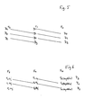
- all light rings D 0 -D 3 can be used with the condenser F 1 .
- the light rings D 1 -D 3 are used for the condenser F 2 , while the light rings with the diameters D 0 -D 2 can be used in the condenser optics F 0 .
- Focal length ratio between the individual condenser optics 6 is particularly advantageous since this Illumination type a fixed relationship between the magnification ratios the condensers 6 and the various magnifications of the lenses 9 exists.
- the other matched Wollaston prisms can be used analogously.
- all of the above lens / condenser combinations can be achieved.
- the condenser system described here is in addition to the optimized use a single light ring set also on the use of wollaston prisms optimized.
Landscapes
- Physics & Mathematics (AREA)
- Chemical & Material Sciences (AREA)
- Analytical Chemistry (AREA)
- General Physics & Mathematics (AREA)
- Optics & Photonics (AREA)
- Microscoopes, Condenser (AREA)
- Instruments For Measurement Of Length By Optical Means (AREA)
Description
- Fig. 1
- einen Beleuchtungsstrahlengang für ein Inversmikroskop mit einer darin angeordneten Revolver-Scheibe und mit einer Kondensoroptik
- Fig. 2
- einen Lichtring in Aufsicht
- Fig. 3
- eine Prinzipdarstellung eines Phasenkontrast-Beleuchtungsstrahlenganges
- Fig. 4
- eine Prinzipdarstellung eines Interferenzkontrast-Beleuchtungsstrahlenganges
- Fig. 5
- die verschiedenen Übemahmemöglichkeiten von Lichtringen bei unterschiedlichen Kondensoren
- Fig. 6
- die verschiedenen Übemahmemöglichkeiten von Wollastonprismen bei unterschiedlichen Kondensor/Objektivkombinationen
Claims (5)
- Wechselbares Kondensorsystem für eine Phasenkontrast-Beleuchtung (12) bei Mikroskopen mit einer Kondensoroptik (6) und dieser zugeordneten, auf einer Revolverscheibe (4) angeordneten unterschiedlichen Lichtringen (5), dadurch gekennzeichnet, daß die Kondensoroptik (6) unabhängig von den Lichtringen (5) wechselbar ist, wobei die Brennweiten Fn der Kondensoroptiken (6) im Verhältnis Fn = F0 * Xn und die mittleren Durchmesser Dn der Lichtringe (5) im Verhältnis Dn = D0 * Xn zueinander gewählt werden, mit X > 0, n = 0,1,2,3...., F0 = Ausgangsbrennweite und D0 = Ausgangsdurchmesser.
- Wechselbares Kondensorsystem für eine Interferenzkontrast-Beleuchtung (15) bei Mikroskopen mit einer Kondensoroptik (6) und dieser zugeordneten, auf einer Revolverscheibe (4) angeordneten unterschiedlichen Wollastonprismen (16) und mit mehreren Objektiven (9) unterschiedlicher Vergrößerung und Brennweite, dadurch gekennzeichnet, daß die Kondensoroptik (6) und die Objektive (9) unabhängig von den Wollastonprismen (16) wechselbar sind, wobei die Brennweiten Fn der Kondensoroptiken (6) im Verhältnis Fn = F0 * Xn und die Brennweiten der Objektive (9) mit dem gleichen Brennweitenverhältnis zueinander gewählt werden, wie die Kondensoroptiken, mit X > 0, n = 0,1,2,3...., und F0 = Ausgangsbrennweite.
- Wechselbares Kondensorsystem nach Anspruch 1 oder Anspruch 2, dadurch gekennzeichnet, daß X=2, F0 = 12 mm und D0 = 2.7 mm beträgt.
- Wechselbares Kondensorsystem nach Anspruch 1 - 3, dadurch gekennzeichnet, daß zur Umschaltung von einer Phasenkontrast-Beleuchtung (12) auf eine Interferenzkontrast-Beleuchtung (15) die Lichtringe (5) und die Wollastonprismen (16) in verschiedenen Aufnahmen derselben Revolverscheibe (4) angeordnet sind.
- Wechselbares Kondensorsystem nach Anspruch 1 - 4, dadurch gekennzeichnet, daß drei Kondensoroptiken (6) und vier Lichtringe (5) und /oder drei Wollastonprismen (16) vorgesehen sind.
Applications Claiming Priority (3)
| Application Number | Priority Date | Filing Date | Title |
|---|---|---|---|
| DE4404283A DE4404283A1 (de) | 1994-02-11 | 1994-02-11 | Kondensorsystem für Mikroskope |
| DE4404283 | 1994-02-11 | ||
| PCT/DE1995/000160 WO1995022072A1 (de) | 1994-02-11 | 1995-02-08 | Kondensorsystem für mikroskope |
Publications (2)
| Publication Number | Publication Date |
|---|---|
| EP0694176A1 EP0694176A1 (de) | 1996-01-31 |
| EP0694176B1 true EP0694176B1 (de) | 2001-10-04 |
Family
ID=6509986
Family Applications (1)
| Application Number | Title | Priority Date | Filing Date |
|---|---|---|---|
| EP95908186A Expired - Lifetime EP0694176B1 (de) | 1994-02-11 | 1995-02-08 | Kondensorsystem für mikroskope |
Country Status (8)
| Country | Link |
|---|---|
| US (1) | US5872651A (de) |
| EP (1) | EP0694176B1 (de) |
| JP (1) | JP3704150B2 (de) |
| KR (1) | KR960701381A (de) |
| CN (1) | CN1048809C (de) |
| AT (1) | ATE206531T1 (de) |
| DE (2) | DE4404283A1 (de) |
| WO (1) | WO1995022072A1 (de) |
Families Citing this family (5)
| Publication number | Priority date | Publication date | Assignee | Title |
|---|---|---|---|---|
| WO1999036822A1 (de) | 1998-01-14 | 1999-07-22 | Leica Microsystems Heidelberg Gmbh | Optische anordnung im beleuchtungsstrahlengang eines mikroskops |
| JP5592043B2 (ja) * | 2000-06-23 | 2014-09-17 | モーメンティブ・パフォーマンス・マテリアルズ・インク | シリコーン感圧接着剤組成物 |
| JP5065059B2 (ja) * | 2008-01-08 | 2012-10-31 | オリンパス株式会社 | 顕微鏡 |
| JP6299409B2 (ja) * | 2014-05-14 | 2018-03-28 | ソニー株式会社 | 位相差顕微鏡及び位相差顕微鏡システム |
| CN111123498A (zh) * | 2019-12-27 | 2020-05-08 | 中国科学院苏州生物医学工程技术研究所 | 一种用于活体细胞观察系统的聚光镜 |
Family Cites Families (11)
| Publication number | Priority date | Publication date | Assignee | Title |
|---|---|---|---|---|
| PL68411A6 (de) * | 1969-05-26 | 1973-02-28 | ||
| US3833283A (en) * | 1971-04-05 | 1974-09-03 | Leitz Ernst Gmbh | Illumination equipment for microscopes |
| US3790254A (en) * | 1972-09-07 | 1974-02-05 | American Optical Corp | Microscope condenser series |
| DE2946927C2 (de) * | 1979-11-21 | 1983-07-07 | Fa. Carl Zeiss, 7920 Heidenheim | Automatische Durchlichtbeleuchtung für Mikroskope |
| JPS587123A (ja) * | 1981-07-06 | 1983-01-14 | Olympus Optical Co Ltd | 高解像結像光学系 |
| US4407569A (en) * | 1981-07-07 | 1983-10-04 | Carl Zeiss-Stiftung | Device for selectively available phase-contrast and relief observation in microscopes |
| DE3711843A1 (de) * | 1987-03-09 | 1988-09-22 | Leitz Ernst Gmbh | Revolver-dreheinrichtung fuer optische bauelemente sowie verfahren zur regelung der drehzahl derselben |
| JPH01154016A (ja) * | 1987-12-10 | 1989-06-16 | Nikon Corp | 顕微鏡 |
| JPH02151825A (ja) * | 1988-12-05 | 1990-06-11 | Olympus Optical Co Ltd | 微分干渉顕微鏡 |
| JPH05232384A (ja) * | 1992-02-18 | 1993-09-10 | Olympus Optical Co Ltd | 干渉顕微鏡 |
| DE4231440A1 (de) * | 1992-09-19 | 1994-03-24 | Leica Mikroskopie & Syst | Universal-Klappkondensor für Mikroskope |
-
1994
- 1994-02-11 DE DE4404283A patent/DE4404283A1/de not_active Ceased
-
1995
- 1995-02-08 JP JP52090395A patent/JP3704150B2/ja not_active Expired - Fee Related
- 1995-02-08 DE DE59509655T patent/DE59509655D1/de not_active Expired - Fee Related
- 1995-02-08 EP EP95908186A patent/EP0694176B1/de not_active Expired - Lifetime
- 1995-02-08 AT AT95908186T patent/ATE206531T1/de not_active IP Right Cessation
- 1995-02-08 CN CN95190083A patent/CN1048809C/zh not_active Expired - Fee Related
- 1995-02-08 KR KR1019950703895A patent/KR960701381A/ko not_active Withdrawn
- 1995-02-08 US US08/530,190 patent/US5872651A/en not_active Expired - Fee Related
- 1995-02-08 WO PCT/DE1995/000160 patent/WO1995022072A1/de not_active Ceased
Also Published As
| Publication number | Publication date |
|---|---|
| US5872651A (en) | 1999-02-16 |
| CN1123058A (zh) | 1996-05-22 |
| EP0694176A1 (de) | 1996-01-31 |
| ATE206531T1 (de) | 2001-10-15 |
| JPH08509078A (ja) | 1996-09-24 |
| KR960701381A (ko) | 1996-02-24 |
| WO1995022072A1 (de) | 1995-08-17 |
| DE59509655D1 (de) | 2001-11-08 |
| JP3704150B2 (ja) | 2005-10-05 |
| DE4404283A1 (de) | 1995-08-17 |
| CN1048809C (zh) | 2000-01-26 |
Similar Documents
| Publication | Publication Date | Title |
|---|---|---|
| DE3530928C2 (de) | ||
| DE3442218C2 (de) | ||
| DE19837135C5 (de) | Afokales Zoomsystem | |
| AT398855B (de) | Mikroskopobjektiv zur einstellung auf unterschiedliche deckglasdicken | |
| EP1544653B1 (de) | Mikroskop mit einem afokalen Zoomsystem | |
| EP0081161B1 (de) | Beleuchtungseinrichtung für Mikroskope | |
| DE2413504C2 (de) | Beleuchtungssystem für ein Durchlicht-Mikroskop | |
| DE2660987C2 (de) | Auflichtbeleuchtungssystem für ein Mikroskop | |
| DE10119369A1 (de) | Beobachtungsvorrichtung | |
| EP0452822A1 (de) | Operationsmikroskop für mindestens zwei Operateure | |
| LU93022B1 (de) | Verfahren und Mikroskop zum Untersuchen einer Probe | |
| EP0688440B1 (de) | Optisches system mit variablem abbildungsmassstab | |
| DE19901219B4 (de) | Optische Anordnung im Beleuchtungsstrahlengang eines Auflichtmikroskops | |
| EP0694176A1 (de) | Kondensorsystem für mikroskope | |
| DE1827188U (de) | Stereomikroskop mit kontinuierlicher aenderung der stereobasis. | |
| DE3700965A1 (de) | Universalkondensor | |
| DE2910747C2 (de) | Kondensorsystem für ein Mikroskop | |
| DE3437879A1 (de) | Stereoskopische optische einrichtung | |
| DE102015225641A1 (de) | Zoomobjektiv | |
| DE102007029894A1 (de) | Mikroskop mit zentrierter Beleuchtung | |
| DE3726355A1 (de) | Bifokales optisches infrarotsystem | |
| DE102005046476A1 (de) | Mikroskopobjektiv | |
| CH680168A5 (de) | ||
| DE20310548U1 (de) | Beleuchtungseinrichtung für eine Beobachtungseinrichtung sowie Beobachtungseinrichtung | |
| DE2259227C3 (de) | Periskop mit Wechsel der Vergrößerung |
Legal Events
| Date | Code | Title | Description |
|---|---|---|---|
| PUAI | Public reference made under article 153(3) epc to a published international application that has entered the european phase |
Free format text: ORIGINAL CODE: 0009012 |
|
| AK | Designated contracting states |
Kind code of ref document: A1 Designated state(s): AT CH DE FR GB LI |
|
| 17P | Request for examination filed |
Effective date: 19960111 |
|
| RAP1 | Party data changed (applicant data changed or rights of an application transferred) |
Owner name: LEICA MICROSYSTEMS WETZLAR GMBH |
|
| GRAG | Despatch of communication of intention to grant |
Free format text: ORIGINAL CODE: EPIDOS AGRA |
|
| 17Q | First examination report despatched |
Effective date: 20001207 |
|
| GRAG | Despatch of communication of intention to grant |
Free format text: ORIGINAL CODE: EPIDOS AGRA |
|
| GRAH | Despatch of communication of intention to grant a patent |
Free format text: ORIGINAL CODE: EPIDOS IGRA |
|
| GRAH | Despatch of communication of intention to grant a patent |
Free format text: ORIGINAL CODE: EPIDOS IGRA |
|
| GRAA | (expected) grant |
Free format text: ORIGINAL CODE: 0009210 |
|
| AK | Designated contracting states |
Kind code of ref document: B1 Designated state(s): AT CH DE FR GB LI |
|
| REF | Corresponds to: |
Ref document number: 206531 Country of ref document: AT Date of ref document: 20011015 Kind code of ref document: T |
|
| REG | Reference to a national code |
Ref country code: CH Ref legal event code: EP |
|
| GBT | Gb: translation of ep patent filed (gb section 77(6)(a)/1977) |
Effective date: 20011004 |
|
| REF | Corresponds to: |
Ref document number: 59509655 Country of ref document: DE Date of ref document: 20011108 |
|
| REG | Reference to a national code |
Ref country code: GB Ref legal event code: IF02 |
|
| PG25 | Lapsed in a contracting state [announced via postgrant information from national office to epo] |
Ref country code: AT Free format text: LAPSE BECAUSE OF NON-PAYMENT OF DUE FEES Effective date: 20020208 |
|
| PG25 | Lapsed in a contracting state [announced via postgrant information from national office to epo] |
Ref country code: LI Free format text: LAPSE BECAUSE OF NON-PAYMENT OF DUE FEES Effective date: 20020228 Ref country code: CH Free format text: LAPSE BECAUSE OF NON-PAYMENT OF DUE FEES Effective date: 20020228 |
|
| ET | Fr: translation filed | ||
| PLBE | No opposition filed within time limit |
Free format text: ORIGINAL CODE: 0009261 |
|
| STAA | Information on the status of an ep patent application or granted ep patent |
Free format text: STATUS: NO OPPOSITION FILED WITHIN TIME LIMIT |
|
| 26N | No opposition filed | ||
| REG | Reference to a national code |
Ref country code: CH Ref legal event code: PL |
|
| PGFP | Annual fee paid to national office [announced via postgrant information from national office to epo] |
Ref country code: DE Payment date: 20090219 Year of fee payment: 15 |
|
| PGFP | Annual fee paid to national office [announced via postgrant information from national office to epo] |
Ref country code: GB Payment date: 20090219 Year of fee payment: 15 |
|
| PGFP | Annual fee paid to national office [announced via postgrant information from national office to epo] |
Ref country code: FR Payment date: 20090213 Year of fee payment: 15 |
|
| GBPC | Gb: european patent ceased through non-payment of renewal fee |
Effective date: 20100208 |
|
| REG | Reference to a national code |
Ref country code: FR Ref legal event code: ST Effective date: 20101029 |
|
| PG25 | Lapsed in a contracting state [announced via postgrant information from national office to epo] |
Ref country code: FR Free format text: LAPSE BECAUSE OF NON-PAYMENT OF DUE FEES Effective date: 20100301 |
|
| PG25 | Lapsed in a contracting state [announced via postgrant information from national office to epo] |
Ref country code: DE Free format text: LAPSE BECAUSE OF NON-PAYMENT OF DUE FEES Effective date: 20100901 |
|
| PG25 | Lapsed in a contracting state [announced via postgrant information from national office to epo] |
Ref country code: GB Free format text: LAPSE BECAUSE OF NON-PAYMENT OF DUE FEES Effective date: 20100208 |