EP0693653B1 - Vorrichtung zum lösbaren Verbinden eines fotografischen oder optischen Gerätes mit einem Stativ oder dergleichen - Google Patents
Vorrichtung zum lösbaren Verbinden eines fotografischen oder optischen Gerätes mit einem Stativ oder dergleichen Download PDFInfo
- Publication number
- EP0693653B1 EP0693653B1 EP95111128A EP95111128A EP0693653B1 EP 0693653 B1 EP0693653 B1 EP 0693653B1 EP 95111128 A EP95111128 A EP 95111128A EP 95111128 A EP95111128 A EP 95111128A EP 0693653 B1 EP0693653 B1 EP 0693653B1
- Authority
- EP
- European Patent Office
- Prior art keywords
- lever
- recess
- screw head
- locking device
- screw
- Prior art date
- Legal status (The legal status is an assumption and is not a legal conclusion. Google has not performed a legal analysis and makes no representation as to the accuracy of the status listed.)
- Expired - Lifetime
Links
- 230000003287 optical effect Effects 0.000 title claims description 5
- 239000011248 coating agent Substances 0.000 description 1
- 238000000576 coating method Methods 0.000 description 1
- 230000000994 depressogenic effect Effects 0.000 description 1
- 230000002349 favourable effect Effects 0.000 description 1
- 239000000463 material Substances 0.000 description 1
Images
Classifications
-
- F—MECHANICAL ENGINEERING; LIGHTING; HEATING; WEAPONS; BLASTING
- F16—ENGINEERING ELEMENTS AND UNITS; GENERAL MEASURES FOR PRODUCING AND MAINTAINING EFFECTIVE FUNCTIONING OF MACHINES OR INSTALLATIONS; THERMAL INSULATION IN GENERAL
- F16M—FRAMES, CASINGS OR BEDS OF ENGINES, MACHINES OR APPARATUS, NOT SPECIFIC TO ENGINES, MACHINES OR APPARATUS PROVIDED FOR ELSEWHERE; STANDS; SUPPORTS
- F16M13/00—Other supports for positioning apparatus or articles; Means for steadying hand-held apparatus or articles
-
- F—MECHANICAL ENGINEERING; LIGHTING; HEATING; WEAPONS; BLASTING
- F16—ENGINEERING ELEMENTS AND UNITS; GENERAL MEASURES FOR PRODUCING AND MAINTAINING EFFECTIVE FUNCTIONING OF MACHINES OR INSTALLATIONS; THERMAL INSULATION IN GENERAL
- F16M—FRAMES, CASINGS OR BEDS OF ENGINES, MACHINES OR APPARATUS, NOT SPECIFIC TO ENGINES, MACHINES OR APPARATUS PROVIDED FOR ELSEWHERE; STANDS; SUPPORTS
- F16M11/00—Stands or trestles as supports for apparatus or articles placed thereon ; Stands for scientific apparatus such as gravitational force meters
- F16M11/02—Heads
- F16M11/04—Means for attachment of apparatus; Means allowing adjustment of the apparatus relatively to the stand
- F16M11/041—Allowing quick release of the apparatus
-
- F—MECHANICAL ENGINEERING; LIGHTING; HEATING; WEAPONS; BLASTING
- F16—ENGINEERING ELEMENTS AND UNITS; GENERAL MEASURES FOR PRODUCING AND MAINTAINING EFFECTIVE FUNCTIONING OF MACHINES OR INSTALLATIONS; THERMAL INSULATION IN GENERAL
- F16M—FRAMES, CASINGS OR BEDS OF ENGINES, MACHINES OR APPARATUS, NOT SPECIFIC TO ENGINES, MACHINES OR APPARATUS PROVIDED FOR ELSEWHERE; STANDS; SUPPORTS
- F16M2200/00—Details of stands or supports
- F16M2200/02—Locking means
- F16M2200/025—Locking means for translational movement
- F16M2200/027—Locking means for translational movement by friction
-
- Y—GENERAL TAGGING OF NEW TECHNOLOGICAL DEVELOPMENTS; GENERAL TAGGING OF CROSS-SECTIONAL TECHNOLOGIES SPANNING OVER SEVERAL SECTIONS OF THE IPC; TECHNICAL SUBJECTS COVERED BY FORMER USPC CROSS-REFERENCE ART COLLECTIONS [XRACs] AND DIGESTS
- Y10—TECHNICAL SUBJECTS COVERED BY FORMER USPC
- Y10T—TECHNICAL SUBJECTS COVERED BY FORMER US CLASSIFICATION
- Y10T403/00—Joints and connections
- Y10T403/59—Manually releaseable latch type
- Y10T403/599—Spring biased manipulator
-
- Y—GENERAL TAGGING OF NEW TECHNOLOGICAL DEVELOPMENTS; GENERAL TAGGING OF CROSS-SECTIONAL TECHNOLOGIES SPANNING OVER SEVERAL SECTIONS OF THE IPC; TECHNICAL SUBJECTS COVERED BY FORMER USPC CROSS-REFERENCE ART COLLECTIONS [XRACs] AND DIGESTS
- Y10—TECHNICAL SUBJECTS COVERED BY FORMER USPC
- Y10T—TECHNICAL SUBJECTS COVERED BY FORMER US CLASSIFICATION
- Y10T403/00—Joints and connections
- Y10T403/60—Biased catch or latch
Definitions
- the invention relates to a device according to the preamble of claim 1.
- a device of this type is known from US-A-3356325.
- the locking device interacts with an actuatable rotary valve, which is movable against the force of a spring, so that in a Position the locking device of the screw head in the recess can be introduced and when the rotary valve is released is held in the recess.
- the invention is therefore based on the object of an arrangement to meet, which speeds up the camera change without the safe Bracket the camera or the like on the tripod.
- the invention is based on one Device of the type specified and beats the in characterizing part of claim 1 listed features in front.
- the photographic or optical device placed on the device with one hand respectively are inserted into the recess with the screw head, the device then automatically detects the screw head and holds in the desired way. After fixing in done in this way, it is then easily possible that photographic or optical device in the device align and rigidly fix.
- the lever is pivotable about an axis and under the action of a Spring stands, which presses the lever against a stop in which the actuating pin is also kept movable.
- a spring stands, which presses the lever against a stop in which the actuating pin is also kept movable.
- the housing is made of there is an upper and a lower part, the two parts each have recesses, which together form a bolt for the Pick up the slide, the lever and the spring. In this way assembly is facilitated and the dimensions of the Device remain small so that they can be accommodated anywhere can be.
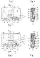
- the device consists essentially of the housing 3 and the knurled wheel 8, which sits on the screw 6.
- the recess 2 is essentially circular and slightly larger than the knurled wheel 8, so that this can be easily introduced.
- the cuboid housing 3, for example, is formed from the Upper part 22 and the lower part 21.
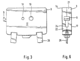
- the lower part 21 has a or several screw holes 18, 19 which are mounted in the Condition on the underside of the housing 3, the threaded screw of the tripod. Through several screw holes 18, 19 with different diameters are different threads of the threaded screws on the tripods.
- the recess 24 will here by cooperating recesses in the upper part 22 or the lower part 21 is formed.
- the pivot lever 9 is in its locking position shown.
- the pivot lever 9 protrudes through the recess 24 into the interior of the housing 3.
- the pivot lever 9 is open a pivot pin 10 mounted, the pivot pin 10 on the side of the housing 3 opposite the recess 24 is provided.
- the pivot pin 10 is parallel to Aligned screw axis.
- Fig. 1 it is shown how the pivot lever 9 with the locking device 4 interacts.
- a spring 11 is arranged, which is a force component causes perpendicular to the axis of the pivot pin 10th works.
- This spring 11 acts on a leg 38 of the pivot lever 9 or the locking device 4.
- the nose 39 is here formed as a rounding 27, this rounding of the rounding on corresponds to the cylindrical part of the knurled wheel.
- the swivel lever 9 or the locking device 4 is L-shaped, the upright web of the L parallel to the Swivel pin 10 is arranged and on one side the Leg 38 and on the other side the nose protruding from the L. 39 forms.
- a bolt 12 protrudes on one longitudinal side through the recess 23 from the housing 3.
- the bolt 12 acts on a slide 44 and is held in a closed position by the spring 29.
- the slide 44 acts on the actuating end 28 on the swivel lever 9. This is part of the separating device 5.
- the swivel lever 9 cannot move downwards of the arrow 40 can be pivoted because this movement is prevented by the actuation end 28 on the slide 30.
- This movement along the arrow 41 takes place against the force of the spring 29.
- the spring 29 is pressed into the recess 25.
- the opening position of the device, which is thereby caused, is shown in FIGS. 1 and 4.
- the knurled wheel 8 is arranged around the screw head 1 of the screw 6.
- the screw 6 is designed as a countersunk screw, and the surface of the head 1 forms with the surface of the knurled wheel 8 a flat surface.
- the knurled wheel 8 has a knurling on a conical intermediate piece 30 ends.
- the conical adapter 30 merges into the cylindrical part 31, which with the Flat surface 32 ends.
- the thread protrudes from the flat surface 32, that is screwed into the corresponding optical device.
- the nose 39, formed as a curve 27, of the locking device 4 has a bevel that is approximately parallel with the surface of the conical intermediate piece 30.
- This sloping surface appears holding the nose 39 together with the conical intermediate piece 30.
- the opening 2 also has one at its edge interior bevel 42. This bevel 42 is approximately parallel to the surface of the conical intermediate piece 30. In the closed, locked position, this part the surface through the locking device to the bevel 42 pressed. The force of the spring 11 thus finds its abutment.
- FIG. 4 the operation of the locking device is shown.
- a lever 35 is movable about the axis 34.
- the spring 33 causes the lever 35th abuts the stop 43.
- This stop 43 is in the Housing 3 fixed, the axis 34 is in the housing on the arranged opposite the latch 12 side.
- This Stop 43 forms on the other side the contact surface for the inserted screw head.
- the stop 43 also carries a pin that is substantially perpendicular to this stop surface is movable and acts on the lever 35. In the 4 position is the lever 35 by the spring 33 pressed against the stop 43 and thus holds the actuating end 28 in the open position.
- a knurled wheel can be fixed in the housing 3, for example also be done by magnetic means, then corresponding Devices for releasing and locking the device be provided.
- a coating 15 in a recess 16 is provided, the surface 17 opposite lies.
- the covering 15 is made of rubber or a similar material and has one of the recess 2 in the region of the recess 2 adjusted opening.
- the covering 15 on his Surface 36 can be equipped with a corrugation.
- the housing 3 on the long side of the housing 3, which has the latch 12 are, for example, two pins 20 between the lower part 21 and the upper part 22 of the housing 3, which is a carrying strap Record 26.
- the pins 20 are at a distance from Housing 3 on.
Landscapes
- Engineering & Computer Science (AREA)
- General Engineering & Computer Science (AREA)
- Mechanical Engineering (AREA)
- Accessories Of Cameras (AREA)
- Camera Bodies And Camera Details Or Accessories (AREA)
Description
- Fig. 1
- eine Draufsicht teilweise im Schnitt einer erfindungsgemäßen Vorrichtung in Entriegelungsstellung,
- Fig. 2
- eine Draufsicht teilweise im Schnitt einer erfindungsgemäßen Vorrichtung in Arretierstellung,
- Fig. 3
- eine Unteransicht einer erfindungsgemäßen Vorrichtung,
- Fig. 4
- eine Schnittdarstellung entsprechend der Schnittlinie IV-IV der Fig. 1,
- Fig. 5
- eine Schnittdarstellung entsprechend der Schnittlinie V-V der Fig. 2 jedoch mit Schraube und Schraubenkopf und
- Fig. 6
- eine Seitenansicht teilweise im Schnitt einer erfindungsgemäßen Vorrichtung in Arretierstellung.
In der Verschlußstellung, wie sie zum Beispiel in Fig. 2 gezeigt ist, wirkt der Schieber 44 auf das Betätigungsende 28 am Schwenkhebel 9. Dies ist Teil der Trennvorrichtung 5. In der in Fig. 2 gezeigten Stellung kann der Schwenkhebel 9 nicht nach unten entlang des Pfeiles 40 geschwenkt werden, weil diese Bewegung durch Anstehen des Betätigungsendes 28 an dem Schieber 30 verhindert wird. Um den Schwenkhebel 9 entlang des Pfeiles 40 verschwenken zu können, ist es zunächst notwendig, den Riegel 12 nach rechts (Fig. 2) entlang des Pfeiles 41 zu bewegen, um den Riegel 30 von dem Betätigungsende 28 zu entfernen. Diese Bewegung entlang des Pfeiles 41 erfolgt gegen die Kraft der Feder 29. Die Feder 29 wird hierbei in die Ausnehmung 25 gepreßt. Die Öffnungsstellung der Vorrichtung, die dadurch bewirkt wird, ist in Fig. 1 und Fig. 4 gezeigt.
Claims (2)
- Vorrichtung zum lösbaren Verbinden eines fotografischen oder optischen Geräts mit einem Stativ oder dergleichen, die ein Gehäuse (3) aufweist, das versehen ist mit einer Ausnehmung (2) für die Aufnahme eines Schraubenkopfes (1) einer in das Gerät, das Stativ oder dergleichen eingeschraubten Schraube (6), mit einer Arretiervorrichtung (4) für das Halten des Schraubenkopfes (1), mit einer betätigbaren Trennvorrichtung (5) zur Freigabe der Arretiervorrichtung (4) und des Schraubenkopfes (1), und mit einem betätigbaren Schieber (44), der in einer ersten Stellung die Trennvorrichtung (5) freigibt und in einer weiteren Stellung die Trennvorrichtung (5) und die Arretiervorrichtung (4) in die Stellung zum Halten des Schraubenkopfes (1) drückt, dadurch gekennzeichnet, daß die Arretiervorrichtung (4) in der ersten Stellung des Schiebers (44) von einem Hebel (35) gehalten ist, wobei am Hebel (35) ein Betätigungsstift (13) anliegt, der in die Ausnehmung (2) hineinragt, um mit dem Schraubenkopf (1) zusammenzuwirken.
- Vorrichtung nach Anspruch 1, dadurch gekennzeichnet, daß der Hebel (35) um eine Achse (34) verschwenkbar ist und unter der Wirkung einer Feder (33) steht, die den Hebel (35) gegen einen Anschlag (43) drückt, in dem auch der Betätigungsstift (13) beweglich gehalten ist.
Applications Claiming Priority (2)
| Application Number | Priority Date | Filing Date | Title |
|---|---|---|---|
| DE9411987U DE9411987U1 (de) | 1994-07-23 | 1994-07-23 | Vorrichtung zum lösbaren Verbinden eines fotografischen oder optischen Gerätes mit einem Stativ o.dgl. |
| DE9411987U | 1994-07-23 |
Publications (2)
| Publication Number | Publication Date |
|---|---|
| EP0693653A1 EP0693653A1 (de) | 1996-01-24 |
| EP0693653B1 true EP0693653B1 (de) | 2001-05-23 |
Family
ID=6911563
Family Applications (1)
| Application Number | Title | Priority Date | Filing Date |
|---|---|---|---|
| EP95111128A Expired - Lifetime EP0693653B1 (de) | 1994-07-23 | 1995-07-15 | Vorrichtung zum lösbaren Verbinden eines fotografischen oder optischen Gerätes mit einem Stativ oder dergleichen |
Country Status (3)
| Country | Link |
|---|---|
| US (1) | US5785286A (de) |
| EP (1) | EP0693653B1 (de) |
| DE (2) | DE9411987U1 (de) |
Families Citing this family (28)
| Publication number | Priority date | Publication date | Assignee | Title |
|---|---|---|---|---|
| DE9411987U1 (de) * | 1994-07-23 | 1994-09-29 | Novoflex Fotogerätebau Karl Müller, 87700 Memmingen | Vorrichtung zum lösbaren Verbinden eines fotografischen oder optischen Gerätes mit einem Stativ o.dgl. |
| US6099197A (en) * | 1995-11-09 | 2000-08-08 | Gauron; Jacques P. | Locking spring-biased latch |
| US6260971B1 (en) | 1999-06-22 | 2001-07-17 | Steve Cardellini | Motion picture camera head tie-down device |
| JP2001213259A (ja) * | 2000-02-03 | 2001-08-07 | Toyoda Gosei Co Ltd | エアバッグ装置を備えたステアリングホイール |
| US20020186316A1 (en) * | 2001-06-11 | 2002-12-12 | Baron John M. | Support sensor |
| ITPD20050186A1 (it) * | 2005-06-21 | 2006-12-22 | Lino Manfrotto & Co Spa | Dispositivo di attacco rapido per attrezzature video e fotografiche |
| CN100465769C (zh) * | 2005-08-09 | 2009-03-04 | 杨永坚 | 带双卡钳锁定的连接器的相机云台 |
| US20070154254A1 (en) * | 2006-01-03 | 2007-07-05 | Bevirt Joeben | Mounting apparatus using ball and socket joints with gripping features |
| US8197149B2 (en) * | 2007-04-27 | 2012-06-12 | Tocad America, Inc. | Apparatuses and systems for supporting and positioning cameras and other equipment |
| USD607036S1 (en) | 2007-04-27 | 2009-12-29 | Tocad America, Inc. | Camera support |
| US20080283697A1 (en) * | 2007-04-27 | 2008-11-20 | Richard Darrow | Apparatuses and systems for supporting and positioning cameras and other equipment |
| USD607917S1 (en) | 2007-04-27 | 2010-01-12 | Tocad America, Inc. | Camera support |
| US20090039213A1 (en) * | 2007-04-27 | 2009-02-12 | Richard Darrow | Apparatuses and systems for supporting and positioning cameras and other equipment |
| CN101598886B (zh) * | 2009-07-07 | 2010-12-29 | 刘昊 | 四轴摄影云台 |
| DE102011013101A1 (de) * | 2011-03-04 | 2012-09-06 | Cullmann Foto-Audio-Video Gmbh | Klemmplatte |
| ITMI20120360A1 (it) * | 2012-03-07 | 2013-09-08 | Iseo Serrature Spa | Maniglione antipanico |
| TWI481783B (zh) * | 2012-10-17 | 2015-04-21 | Qisda Corp | 卡合固定模組 |
| CN106437408A (zh) * | 2016-08-31 | 2017-02-22 | 吴华琴 | 一种保险箱锁定装置 |
| CN106276013B (zh) * | 2016-08-31 | 2019-01-29 | 湖南惠欣源生态农业开发有限公司 | 一种物流货箱存放锁定装置 |
| CN106090578B (zh) * | 2016-08-31 | 2018-07-20 | 宋佳 | 一种用于电视机的安装装置 |
| GB2555421B (en) * | 2016-10-26 | 2021-08-04 | Kohler Mira Ltd | Slide rail mechanism |
| US10697583B2 (en) | 2017-01-04 | 2020-06-30 | Google Llc | Mount attachment for an electronic device |
| US11924532B2 (en) | 2017-01-04 | 2024-03-05 | Google Llc | Camera assembly with concave-shaped front face |
| US10277785B2 (en) | 2017-01-04 | 2019-04-30 | Google Llc | Camera assembly with concave-shaped front face |
| US10602035B2 (en) | 2017-09-19 | 2020-03-24 | Google Llc | Temperature-controlled camera assembly |
| CN111692474B (zh) * | 2020-06-24 | 2022-08-09 | 深圳宏伟时代自控有限公司 | 一种楼宇自控系统用识别人像的监控设备 |
| NO346511B1 (en) * | 2021-06-09 | 2022-09-12 | Tor Korshamn | Tool for fastening and releasing a wall anchor |
| DE102022206462B3 (de) * | 2022-06-27 | 2023-08-17 | Fidlock Gmbh | Haltevorrichtung zum Halten eines Gegenstands an einer Baugruppe |
Family Cites Families (17)
| Publication number | Priority date | Publication date | Assignee | Title |
|---|---|---|---|---|
| US534912A (en) * | 1895-02-26 | Enoch wood perry | ||
| US1119412A (en) * | 1913-05-31 | 1914-12-01 | Donegan Auto Body And Specialty Company | Supporting means for automobile-tops. |
| US3006052A (en) * | 1959-01-13 | 1961-10-31 | Donald B Stickney | Instrument attaching device |
| US3184196A (en) * | 1964-04-20 | 1965-05-18 | Harry D Dent | Mounting device |
| US3356325A (en) * | 1965-10-22 | 1967-12-05 | Davidson Optronics Inc | Camera-to-tripod connector |
| US3549113A (en) * | 1968-05-16 | 1970-12-22 | Robert J Pagliuso | Camera attachment for tripods |
| US3612462A (en) * | 1969-08-26 | 1971-10-12 | Quick Set Inc | Instrument mount assembly |
| US4057816A (en) * | 1976-01-13 | 1977-11-08 | Polaroid Corporation | Accessory adapter |
| JPS57150838A (en) * | 1981-03-13 | 1982-09-17 | Canon Inc | Strap detachable and attachable device |
| US4570887A (en) * | 1983-10-17 | 1986-02-18 | Banister Gerald K | Quick-connect mount for a camera and tripod |
| JPS6440792A (en) * | 1987-08-07 | 1989-02-13 | Nippon Velbon Seiki Kogyo | Universal head |
| US4899189A (en) * | 1988-10-31 | 1990-02-06 | Frost George E | Support and protective base device for camera |
| DE9016714U1 (de) * | 1990-01-29 | 1991-02-28 | Burk, Oswald, Dipl.-Ing., 8000 München | Schnellwechselplatte zur Befestigung von Kameras o.dgl. auf Stativen |
| DE4008529C1 (de) * | 1990-03-16 | 1991-08-14 | Hama Hamaphot Kg, Hanke & Thomas, 8855 Monheim, De | |
| JPH0544890A (ja) * | 1991-08-09 | 1993-02-23 | Heiwa Seiki Kogyo Kk | 雲 台 |
| US5333023A (en) * | 1992-10-02 | 1994-07-26 | Oxford Jerry J | Camera quick release |
| DE9411987U1 (de) * | 1994-07-23 | 1994-09-29 | Novoflex Fotogerätebau Karl Müller, 87700 Memmingen | Vorrichtung zum lösbaren Verbinden eines fotografischen oder optischen Gerätes mit einem Stativ o.dgl. |
-
1994
- 1994-07-23 DE DE9411987U patent/DE9411987U1/de not_active Expired - Lifetime
-
1995
- 1995-07-15 EP EP95111128A patent/EP0693653B1/de not_active Expired - Lifetime
- 1995-07-15 DE DE59509275T patent/DE59509275D1/de not_active Expired - Fee Related
- 1995-07-21 US US08/505,394 patent/US5785286A/en not_active Expired - Fee Related
Also Published As
| Publication number | Publication date |
|---|---|
| US5785286A (en) | 1998-07-28 |
| DE59509275D1 (de) | 2001-06-28 |
| DE9411987U1 (de) | 1994-09-29 |
| EP0693653A1 (de) | 1996-01-24 |
Similar Documents
| Publication | Publication Date | Title |
|---|---|---|
| EP0693653A1 (de) | Vorrichtung zum lösbaren Verbinden eines fotografischen oder optischen Gerätes mit einem Stativ oder dergleichen | |
| DE69709277T2 (de) | Mehrzweck-Verriegelungseinrichtung | |
| EP1849427B1 (de) | Chirurgische Kopfklemme | |
| DE19722969C1 (de) | Rohrkupplung | |
| DE102017108209B4 (de) | Schutzabdeckung für ein schleifgerät | |
| EP0925099A1 (de) | Stockgriff mit handschlaufe | |
| DE4216971A1 (de) | Zange zum Fassen und Halten von Gewebe oder dergleichen | |
| EP0084324A1 (de) | Längsverstelleinrichtung für eine Skibindung | |
| DE10008277B4 (de) | Schließvorrichtung | |
| EP2708791A2 (de) | Schnellspannvorrichtung für ein optisches Gerät | |
| DE69704910T2 (de) | Stock mit änderlicher Länge und Verriegelungsvorrichtung dafür | |
| EP0197058A1 (de) | Sicherheitshelm, insbesondere sturzhelm. | |
| EP1582903A1 (de) | Vorrichtung zum Befestigen eines Mikroskophalters | |
| DE102009045579B4 (de) | Wechselarmatur für eine Messsonde | |
| DE10209866C1 (de) | Kugelkopfkupplung | |
| DE4018414C2 (de) | Vorrichtung zum Abstützen und Befestigen von Objektiven, Objektivteilen und/oder Objektivvorsätzen für eine Kamera | |
| DE9320849U1 (de) | Osteosynthesehilfsmittel für die Fixation von Knochen | |
| DE10127425A1 (de) | Offenhaltevorrichtung für einen beweglichen Verschluss | |
| DE102014108891A1 (de) | Lenker-Verriegelungs-Vorrichtung für ein Fahrrad | |
| DE102018005709B3 (de) | Sägevorsatz für eine Baumschere | |
| DE102004017734B4 (de) | Torquer zum Halten und Führen eines Führungsdrahts | |
| DE69220934T2 (de) | Verstellbarer Maulschlüssel | |
| DE8023855U1 (de) | Brillengestell | |
| DE202018103211U1 (de) | Stützvorrichtung | |
| DE2808788A1 (de) | Vorrichtung zur befestigung von kameras o.dgl. auf stativen |
Legal Events
| Date | Code | Title | Description |
|---|---|---|---|
| PUAI | Public reference made under article 153(3) epc to a published international application that has entered the european phase |
Free format text: ORIGINAL CODE: 0009012 |
|
| AK | Designated contracting states |
Kind code of ref document: A1 Designated state(s): DE FR GB IT |
|
| 17P | Request for examination filed |
Effective date: 19960514 |
|
| 17Q | First examination report despatched |
Effective date: 19970825 |
|
| GRAG | Despatch of communication of intention to grant |
Free format text: ORIGINAL CODE: EPIDOS AGRA |
|
| GRAG | Despatch of communication of intention to grant |
Free format text: ORIGINAL CODE: EPIDOS AGRA |
|
| GRAH | Despatch of communication of intention to grant a patent |
Free format text: ORIGINAL CODE: EPIDOS IGRA |
|
| GRAH | Despatch of communication of intention to grant a patent |
Free format text: ORIGINAL CODE: EPIDOS IGRA |
|
| GRAA | (expected) grant |
Free format text: ORIGINAL CODE: 0009210 |
|
| AK | Designated contracting states |
Kind code of ref document: B1 Designated state(s): DE FR GB IT |
|
| PG25 | Lapsed in a contracting state [announced via postgrant information from national office to epo] |
Ref country code: IT Free format text: LAPSE BECAUSE OF FAILURE TO SUBMIT A TRANSLATION OF THE DESCRIPTION OR TO PAY THE FEE WITHIN THE PRE;WARNING: LAPSES OF ITALIAN PATENTS WITH EFFECTIVE DATE BEFORE 2007 MAY HAVE OCCURRED AT ANY TIME BEFORE 2007. THE CORRECT EFFECTIVE DATE MAY BE DIFFERENT FROM THE ONE RECORDED.SCRIBED TIME-LIMIT Effective date: 20010523 Ref country code: GB Free format text: LAPSE BECAUSE OF FAILURE TO SUBMIT A TRANSLATION OF THE DESCRIPTION OR TO PAY THE FEE WITHIN THE PRESCRIBED TIME-LIMIT Effective date: 20010523 Ref country code: FR Free format text: LAPSE BECAUSE OF FAILURE TO SUBMIT A TRANSLATION OF THE DESCRIPTION OR TO PAY THE FEE WITHIN THE PRESCRIBED TIME-LIMIT Effective date: 20010523 |
|
| REF | Corresponds to: |
Ref document number: 59509275 Country of ref document: DE Date of ref document: 20010628 |
|
| GBV | Gb: ep patent (uk) treated as always having been void in accordance with gb section 77(7)/1977 [no translation filed] |
Effective date: 20010523 |
|
| EN | Fr: translation not filed | ||
| PLBE | No opposition filed within time limit |
Free format text: ORIGINAL CODE: 0009261 |
|
| STAA | Information on the status of an ep patent application or granted ep patent |
Free format text: STATUS: NO OPPOSITION FILED WITHIN TIME LIMIT |
|
| 26N | No opposition filed | ||
| PGFP | Annual fee paid to national office [announced via postgrant information from national office to epo] |
Ref country code: DE Payment date: 20080920 Year of fee payment: 14 |
|
| PG25 | Lapsed in a contracting state [announced via postgrant information from national office to epo] |
Ref country code: DE Free format text: LAPSE BECAUSE OF NON-PAYMENT OF DUE FEES Effective date: 20100202 |