EP0692273B1 - Cathéter comprenant un dispositif de nébulisation et son procédé de fabrication - Google Patents
Cathéter comprenant un dispositif de nébulisation et son procédé de fabrication Download PDFInfo
- Publication number
- EP0692273B1 EP0692273B1 EP95304223A EP95304223A EP0692273B1 EP 0692273 B1 EP0692273 B1 EP 0692273B1 EP 95304223 A EP95304223 A EP 95304223A EP 95304223 A EP95304223 A EP 95304223A EP 0692273 B1 EP0692273 B1 EP 0692273B1
- Authority
- EP
- European Patent Office
- Prior art keywords
- catheter
- liquid
- distal
- lumen
- gas
- Prior art date
- Legal status (The legal status is an assumption and is not a legal conclusion. Google has not performed a legal analysis and makes no representation as to the accuracy of the status listed.)
- Expired - Lifetime
Links
Images


Classifications
-
- A—HUMAN NECESSITIES
- A61—MEDICAL OR VETERINARY SCIENCE; HYGIENE
- A61M—DEVICES FOR INTRODUCING MEDIA INTO, OR ONTO, THE BODY; DEVICES FOR TRANSDUCING BODY MEDIA OR FOR TAKING MEDIA FROM THE BODY; DEVICES FOR PRODUCING OR ENDING SLEEP OR STUPOR
- A61M25/00—Catheters; Hollow probes
- A61M25/0021—Catheters; Hollow probes characterised by the form of the tubing
- A61M25/0023—Catheters; Hollow probes characterised by the form of the tubing by the form of the lumen, e.g. cross-section, variable diameter
- A61M25/0026—Multi-lumen catheters with stationary elements
- A61M25/003—Multi-lumen catheters with stationary elements characterized by features relating to least one lumen located at the distal part of the catheter, e.g. filters, plugs or valves
-
- A—HUMAN NECESSITIES
- A61—MEDICAL OR VETERINARY SCIENCE; HYGIENE
- A61M—DEVICES FOR INTRODUCING MEDIA INTO, OR ONTO, THE BODY; DEVICES FOR TRANSDUCING BODY MEDIA OR FOR TAKING MEDIA FROM THE BODY; DEVICES FOR PRODUCING OR ENDING SLEEP OR STUPOR
- A61M25/00—Catheters; Hollow probes
-
- A—HUMAN NECESSITIES
- A61—MEDICAL OR VETERINARY SCIENCE; HYGIENE
- A61M—DEVICES FOR INTRODUCING MEDIA INTO, OR ONTO, THE BODY; DEVICES FOR TRANSDUCING BODY MEDIA OR FOR TAKING MEDIA FROM THE BODY; DEVICES FOR PRODUCING OR ENDING SLEEP OR STUPOR
- A61M11/00—Sprayers or atomisers specially adapted for therapeutic purposes
- A61M11/001—Particle size control
-
- A—HUMAN NECESSITIES
- A61—MEDICAL OR VETERINARY SCIENCE; HYGIENE
- A61M—DEVICES FOR INTRODUCING MEDIA INTO, OR ONTO, THE BODY; DEVICES FOR TRANSDUCING BODY MEDIA OR FOR TAKING MEDIA FROM THE BODY; DEVICES FOR PRODUCING OR ENDING SLEEP OR STUPOR
- A61M11/00—Sprayers or atomisers specially adapted for therapeutic purposes
- A61M11/005—Sprayers or atomisers specially adapted for therapeutic purposes using ultrasonics
-
- A—HUMAN NECESSITIES
- A61—MEDICAL OR VETERINARY SCIENCE; HYGIENE
- A61M—DEVICES FOR INTRODUCING MEDIA INTO, OR ONTO, THE BODY; DEVICES FOR TRANSDUCING BODY MEDIA OR FOR TAKING MEDIA FROM THE BODY; DEVICES FOR PRODUCING OR ENDING SLEEP OR STUPOR
- A61M16/00—Devices for influencing the respiratory system of patients by gas treatment, e.g. mouth-to-mouth respiration; Tracheal tubes
- A61M16/04—Tracheal tubes
- A61M16/0402—Special features for tracheal tubes not otherwise provided for
- A61M16/0404—Special features for tracheal tubes not otherwise provided for with means for selective or partial lung respiration
-
- A—HUMAN NECESSITIES
- A61—MEDICAL OR VETERINARY SCIENCE; HYGIENE
- A61M—DEVICES FOR INTRODUCING MEDIA INTO, OR ONTO, THE BODY; DEVICES FOR TRANSDUCING BODY MEDIA OR FOR TAKING MEDIA FROM THE BODY; DEVICES FOR PRODUCING OR ENDING SLEEP OR STUPOR
- A61M16/00—Devices for influencing the respiratory system of patients by gas treatment, e.g. mouth-to-mouth respiration; Tracheal tubes
- A61M16/04—Tracheal tubes
- A61M16/0402—Special features for tracheal tubes not otherwise provided for
- A61M16/042—Special features for tracheal tubes not otherwise provided for with separate conduits for in-and expiration gas, e.g. for limited dead volume
-
- A—HUMAN NECESSITIES
- A61—MEDICAL OR VETERINARY SCIENCE; HYGIENE
- A61M—DEVICES FOR INTRODUCING MEDIA INTO, OR ONTO, THE BODY; DEVICES FOR TRANSDUCING BODY MEDIA OR FOR TAKING MEDIA FROM THE BODY; DEVICES FOR PRODUCING OR ENDING SLEEP OR STUPOR
- A61M16/00—Devices for influencing the respiratory system of patients by gas treatment, e.g. mouth-to-mouth respiration; Tracheal tubes
- A61M16/04—Tracheal tubes
- A61M16/0463—Tracheal tubes combined with suction tubes, catheters or the like; Outside connections
-
- A—HUMAN NECESSITIES
- A61—MEDICAL OR VETERINARY SCIENCE; HYGIENE
- A61M—DEVICES FOR INTRODUCING MEDIA INTO, OR ONTO, THE BODY; DEVICES FOR TRANSDUCING BODY MEDIA OR FOR TAKING MEDIA FROM THE BODY; DEVICES FOR PRODUCING OR ENDING SLEEP OR STUPOR
- A61M16/00—Devices for influencing the respiratory system of patients by gas treatment, e.g. mouth-to-mouth respiration; Tracheal tubes
- A61M16/04—Tracheal tubes
- A61M16/0475—Tracheal tubes having openings in the tube
- A61M16/0477—Tracheal tubes having openings in the tube with incorporated means for delivering or removing fluids
- A61M16/0484—Tracheal tubes having openings in the tube with incorporated means for delivering or removing fluids at the distal end
-
- A—HUMAN NECESSITIES
- A61—MEDICAL OR VETERINARY SCIENCE; HYGIENE
- A61M—DEVICES FOR INTRODUCING MEDIA INTO, OR ONTO, THE BODY; DEVICES FOR TRANSDUCING BODY MEDIA OR FOR TAKING MEDIA FROM THE BODY; DEVICES FOR PRODUCING OR ENDING SLEEP OR STUPOR
- A61M16/00—Devices for influencing the respiratory system of patients by gas treatment, e.g. mouth-to-mouth respiration; Tracheal tubes
- A61M16/04—Tracheal tubes
- A61M16/0486—Multi-lumen tracheal tubes
-
- A—HUMAN NECESSITIES
- A61—MEDICAL OR VETERINARY SCIENCE; HYGIENE
- A61M—DEVICES FOR INTRODUCING MEDIA INTO, OR ONTO, THE BODY; DEVICES FOR TRANSDUCING BODY MEDIA OR FOR TAKING MEDIA FROM THE BODY; DEVICES FOR PRODUCING OR ENDING SLEEP OR STUPOR
- A61M11/00—Sprayers or atomisers specially adapted for therapeutic purposes
- A61M11/06—Sprayers or atomisers specially adapted for therapeutic purposes of the injector type
-
- A—HUMAN NECESSITIES
- A61—MEDICAL OR VETERINARY SCIENCE; HYGIENE
- A61M—DEVICES FOR INTRODUCING MEDIA INTO, OR ONTO, THE BODY; DEVICES FOR TRANSDUCING BODY MEDIA OR FOR TAKING MEDIA FROM THE BODY; DEVICES FOR PRODUCING OR ENDING SLEEP OR STUPOR
- A61M15/00—Inhalators
-
- A—HUMAN NECESSITIES
- A61—MEDICAL OR VETERINARY SCIENCE; HYGIENE
- A61M—DEVICES FOR INTRODUCING MEDIA INTO, OR ONTO, THE BODY; DEVICES FOR TRANSDUCING BODY MEDIA OR FOR TAKING MEDIA FROM THE BODY; DEVICES FOR PRODUCING OR ENDING SLEEP OR STUPOR
- A61M15/00—Inhalators
- A61M15/02—Inhalators with activated or ionised fluids, e.g. electrohydrodynamic [EHD] or electrostatic devices; Ozone-inhalators with radioactive tagged particles
- A61M15/025—Bubble jet droplet ejection devices
-
- A—HUMAN NECESSITIES
- A61—MEDICAL OR VETERINARY SCIENCE; HYGIENE
- A61M—DEVICES FOR INTRODUCING MEDIA INTO, OR ONTO, THE BODY; DEVICES FOR TRANSDUCING BODY MEDIA OR FOR TAKING MEDIA FROM THE BODY; DEVICES FOR PRODUCING OR ENDING SLEEP OR STUPOR
- A61M25/00—Catheters; Hollow probes
- A61M25/0021—Catheters; Hollow probes characterised by the form of the tubing
- A61M25/0023—Catheters; Hollow probes characterised by the form of the tubing by the form of the lumen, e.g. cross-section, variable diameter
- A61M25/0026—Multi-lumen catheters with stationary elements
- A61M2025/0035—Multi-lumen catheters with stationary elements characterized by a variable lumen cross-section by means of a resilient flexible septum or outer wall
-
- A—HUMAN NECESSITIES
- A61—MEDICAL OR VETERINARY SCIENCE; HYGIENE
- A61M—DEVICES FOR INTRODUCING MEDIA INTO, OR ONTO, THE BODY; DEVICES FOR TRANSDUCING BODY MEDIA OR FOR TAKING MEDIA FROM THE BODY; DEVICES FOR PRODUCING OR ENDING SLEEP OR STUPOR
- A61M25/00—Catheters; Hollow probes
- A61M25/0021—Catheters; Hollow probes characterised by the form of the tubing
- A61M25/0023—Catheters; Hollow probes characterised by the form of the tubing by the form of the lumen, e.g. cross-section, variable diameter
- A61M25/0026—Multi-lumen catheters with stationary elements
- A61M2025/0036—Multi-lumen catheters with stationary elements with more than four lumina
-
- A—HUMAN NECESSITIES
- A61—MEDICAL OR VETERINARY SCIENCE; HYGIENE
- A61M—DEVICES FOR INTRODUCING MEDIA INTO, OR ONTO, THE BODY; DEVICES FOR TRANSDUCING BODY MEDIA OR FOR TAKING MEDIA FROM THE BODY; DEVICES FOR PRODUCING OR ENDING SLEEP OR STUPOR
- A61M25/00—Catheters; Hollow probes
- A61M25/0021—Catheters; Hollow probes characterised by the form of the tubing
- A61M25/0023—Catheters; Hollow probes characterised by the form of the tubing by the form of the lumen, e.g. cross-section, variable diameter
- A61M25/0026—Multi-lumen catheters with stationary elements
- A61M2025/0037—Multi-lumen catheters with stationary elements characterized by lumina being arranged side-by-side
-
- A—HUMAN NECESSITIES
- A61—MEDICAL OR VETERINARY SCIENCE; HYGIENE
- A61M—DEVICES FOR INTRODUCING MEDIA INTO, OR ONTO, THE BODY; DEVICES FOR TRANSDUCING BODY MEDIA OR FOR TAKING MEDIA FROM THE BODY; DEVICES FOR PRODUCING OR ENDING SLEEP OR STUPOR
- A61M25/00—Catheters; Hollow probes
- A61M25/0021—Catheters; Hollow probes characterised by the form of the tubing
- A61M25/0023—Catheters; Hollow probes characterised by the form of the tubing by the form of the lumen, e.g. cross-section, variable diameter
- A61M25/0026—Multi-lumen catheters with stationary elements
- A61M2025/0039—Multi-lumen catheters with stationary elements characterized by lumina being arranged coaxially
-
- A—HUMAN NECESSITIES
- A61—MEDICAL OR VETERINARY SCIENCE; HYGIENE
- A61M—DEVICES FOR INTRODUCING MEDIA INTO, OR ONTO, THE BODY; DEVICES FOR TRANSDUCING BODY MEDIA OR FOR TAKING MEDIA FROM THE BODY; DEVICES FOR PRODUCING OR ENDING SLEEP OR STUPOR
- A61M25/00—Catheters; Hollow probes
- A61M25/0021—Catheters; Hollow probes characterised by the form of the tubing
- A61M25/0023—Catheters; Hollow probes characterised by the form of the tubing by the form of the lumen, e.g. cross-section, variable diameter
- A61M25/0026—Multi-lumen catheters with stationary elements
- A61M2025/004—Multi-lumen catheters with stationary elements characterized by lumina being arranged circumferentially
-
- A—HUMAN NECESSITIES
- A61—MEDICAL OR VETERINARY SCIENCE; HYGIENE
- A61M—DEVICES FOR INTRODUCING MEDIA INTO, OR ONTO, THE BODY; DEVICES FOR TRANSDUCING BODY MEDIA OR FOR TAKING MEDIA FROM THE BODY; DEVICES FOR PRODUCING OR ENDING SLEEP OR STUPOR
- A61M25/00—Catheters; Hollow probes
- A61M25/0067—Catheters; Hollow probes characterised by the distal end, e.g. tips
- A61M25/0068—Static characteristics of the catheter tip, e.g. shape, atraumatic tip, curved tip or tip structure
- A61M2025/0073—Tip designed for influencing the flow or the flow velocity of the fluid, e.g. inserts for twisted or vortex flow
-
- A—HUMAN NECESSITIES
- A61—MEDICAL OR VETERINARY SCIENCE; HYGIENE
- A61M—DEVICES FOR INTRODUCING MEDIA INTO, OR ONTO, THE BODY; DEVICES FOR TRANSDUCING BODY MEDIA OR FOR TAKING MEDIA FROM THE BODY; DEVICES FOR PRODUCING OR ENDING SLEEP OR STUPOR
- A61M2205/00—General characteristics of the apparatus
- A61M2205/02—General characteristics of the apparatus characterised by a particular materials
- A61M2205/0266—Shape memory materials
-
- A—HUMAN NECESSITIES
- A61—MEDICAL OR VETERINARY SCIENCE; HYGIENE
- A61M—DEVICES FOR INTRODUCING MEDIA INTO, OR ONTO, THE BODY; DEVICES FOR TRANSDUCING BODY MEDIA OR FOR TAKING MEDIA FROM THE BODY; DEVICES FOR PRODUCING OR ENDING SLEEP OR STUPOR
- A61M25/00—Catheters; Hollow probes
- A61M25/0009—Making of catheters or other medical or surgical tubes
-
- A—HUMAN NECESSITIES
- A61—MEDICAL OR VETERINARY SCIENCE; HYGIENE
- A61M—DEVICES FOR INTRODUCING MEDIA INTO, OR ONTO, THE BODY; DEVICES FOR TRANSDUCING BODY MEDIA OR FOR TAKING MEDIA FROM THE BODY; DEVICES FOR PRODUCING OR ENDING SLEEP OR STUPOR
- A61M25/00—Catheters; Hollow probes
- A61M25/0067—Catheters; Hollow probes characterised by the distal end, e.g. tips
- A61M25/0068—Static characteristics of the catheter tip, e.g. shape, atraumatic tip, curved tip or tip structure
- A61M25/0071—Multiple separate lumens
Definitions
- the present invention relates to aerosol delivery of medication, and more particularly, but not exclusively, the present invention relates to delivery systems for application of nebulized medication to the lungs with improved delivery rates, efficiencies, and control.
- Medication delivered through the respiratory tract may be carried with a patient's inhalation breath as airborne particles (e.g. an aerosol or nebula) into the lungs where the medication can cross through the thin membrane of the alveoli and enter the patient's bloodstream. Delivery of medication via the respiratory tract may be preferred in many circumstances because medication delivered this way enters the bloodstream very rapidly. Delivery of medication to the lungs may also be preferred when the medication is used in a treatment of a disease or condition affecting the lungs in order to apply or target the medication as close as physically possible to the diseased area.
- Aerosols in general are relatively short-lived and can settle out into larger particles or droplets relatively quickly. Aerosols can also impact each other or other objects, settle out as sediment, diffuse, or coalesce. Aerosol particles can also be subject to hydroscopic growth as they travel. Delivery of medicine as airborne particles requires conversion of the medicine, which may be in liquid form, to an aerosol followed relatively quickly by application of the aerosol to the respiratory tract.
- One such device that has been utilized for this purpose is an inhaler. Inhalers may atomize a liquid to form an aerosol which a person inhales via the mouth or nose. Inhalers typically provide only limited delivery of medication to the lungs since most of the medication is deposited on the linings of the respiratory tract. It is estimated that as little as 10-15 % of an aerosol inhaled in this way reaches the alveoli.
- Aerosol delivery of a medication to a patient's respiratory tract also may be performed while the patient is intubated, i.e. when an endotracheal tube is positioned in the patient's trachea to assist in breathing.
- an endotracheal tube When an endotracheal tube is positioned in a patient, a proximal end of the endotracheal tube may be connected to a mechanical ventilator and the distal end is located in the trachea.
- An aerosol may be added to the airflow in the ventilator circuit of the endotracheal tube and carried by the patient's inhalation to the lungs. A significant amount of the aerosolized medication may be deposited inside the endotracheal tube and the delivery rate of the medicine to the lungs also remains relatively low and unpredictable.
- US-A-4 739 756 discloses an endotracheal tube adapted to deliver an aerosol to a patient's lungs. Multiple orifices are arranged around the distal end of a ventilation lumen and are in communication with a single medicament supply lumen.
- an improved aerosol delivery system may provide for improved rates and efficiencies of delivery also taking into account the aerosol particle size.
- aerosol delivery via the respiratory tract could become an even more widely used and effective means of medication delivery if the delivery rate and efficiency of the delivery could be improved.
- an apparatus for delivering a drug with control and efficiency to a patient via the patient's respiratory system comprising a catheter shaft having a liquid lumen centrally located in said shaft and adapted for conveying a medicine in liquid form; a plurality of gas lumens peripherally located around said liquid lumen and adapted for conveying a gas; a distal liquid orifice communicating with said liquid lumen; and, a plurality of distal gas orifices communicating with said plurality of gas lumens, said plurality of gas orifices being aligned with respect to said distal liquid orifice so as to nebulize a liquid medicine discharged from the liquid orifice.
- the nebulization catheter is positioned in the patient's respiratory system so that a distal end of the nebulization catheter is in the respiratory system and a proximal end is outside the body.
- the nebulization catheter may be used in conjunction with an endotracheal tube and preferably is removable from the endotracheal tube.
- the nebulization catheter conveys medicine in liquid form to the distal end at which location the medicine is nebulized by a pressurized gas or other nebulizing agent.
- the nebulized medicine is conveyed to the patient's lungs by the patient's respiration which may be assisted by a ventilator.
- the nebulizing catheter incorporates alternative constructions taking into account anatomical considerations and the properties of the medicine being nebulized to provide delivery of medicine with control and efficiency.
- the invention further resides in a method of manufacturing a catheter as specified above but having a tapering distal tip region, the catheter having closely spaced distal orifices sized and spaced apart with low tolerances, and the method comprising the steps of:
- the present invention facilitates the provision of controlled and efficient delivery of an aerosolized medication to the lungs of a patient by nebulization of a medication at a distal end of a catheter positioned in the respiratory tract.
- the nebulization catheter is described as used for the delivery of medicine or medication. It is intended that the terms "medication”, “medicine”, and “drug” should be understood to include other agents that can be delivered to the lungs for diagnostic or therapeutic purposes, such as tracers, or for humidification.
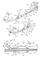
- FIGS. 1 and 2 show an endotracheal tube 10 which may be a conventional endotracheal tube.
- the endotracheal tube 10 may have an inflatable cuff 12 located close to its distal end to facilitate positioning the tube 10 in the patient's trachea, or alternatively the endotracheal tube 10 may be of a type without an inflatable cuff.
- the inflatable cuff 12 is connected via a separate inflation lumen in the endotracheal tube 10 to a proximal fitting 13 for connection to a source of inflating gas (not shown).
- the endotracheal tube 10 has a proximal end connected to a manifold fitting 14.
- the fitting 14 has a port 15 suitably adapted for connection to a ventilator circuit (not shown).
- the fitting 14 also includes another port 16 that permits the introduction of a separate catheter into the endotracheal tube from the proximal end.
- the fitting 14 may be similar in construction to the elbow fitting described in U.S. Pat. No. 5,078,131 (Foley), the entire disclosure of which is incorporated herein by reference.
- a nebulizing catheter 20 which is described herein forfacilitating an understanding of the invention, is located in a position ready to be inserted into a ventilation lumen 22 of the endotracheal tube 10 via the proximal fitting 14.
- the nebulizing catheter 20 is positioned fully in the endotracheal tube 10 with a proximal end extending out of the port 16 of the proximal fitting 14.
- the manifold 24 includes at least a gas port 28 and a liquid (medicine) port 32.
- These ports 28 and 32 may include conventional attaching means, such as luer lock type fittings.
- these ports 28 and 32 may also include closure caps 31 that may be used to close the ports when not in use and may be popped open when connection to a gas source or a liquid source is desired.
- the manifold 24 may also include a filter located in-line with either the gas port 28 or the liquid port 32 or both ports to prevent lumen blockages by particulate matter.
- the nebulization catheter 20 includes at least two separate lumens (as shown in FIG. 2A).
- a first lumen 33 is used for conveyance of a liquid medicine and communicates with the port 32 on the manifold 24.
- the other lumen 34 is used for conveyance of a pressurized gas and communicates with the port 28 on the manifold 24.
- the liquid lumen 33 communicates with a distal liquid orifice 35 and the gas lumen 34 communicates with a distal gas orifice 36 near a distal end 37 of the nebulization catheter 20.
- the distal opening 36 of the pressurized gas lumen 34 directs pressurized gas across the distal liquid lumen opening 35 thereby nebulizing the liquid medication so that it can be delivered to the patient's lungs.
- the distal liquid orifice 35 may be open or may be provided with a porous material plug or a sponge-like or felt-like material plug which may extend slightly from the distal orifice and that allows liquid to flow from the orifice yet reduces the likelihood of liquid drooling from the tip.
- the length of the nebulization catheter 20 should be sufficient so that the distal end 37 can be located in the desired location in the respiratory system while the proximal end (i.e., including the manifold 24) is accessible to the physician or other medical personnel for connection to suitable gas and liquid supplies external of the patient's body. Accordingly, the length of the nebulization catheter is dependant upon the size of the patient in which it is being used. A shorter nebulization catheter may be preferred in smaller patients, such as infants or children, and a longer nebulization catheter may be needed for adults. For example, a nebulization catheter suitable for adults may have a length of approximately 45 cm.
- nebulizing catheter 20 approximately 30 cm of the nebulizing catheter 20 is in the endotracheal tube 10.
- the nebulization catheter may be introduced into the respiratory system through a patient's mouth or via a tracheostomy tube or through the nasal passages.
- the nebulization catheter may also be used to deliver an aerosol to a patient's nasal passages in which case the length may be correspondingly shorter.
- the generation of an aerosol plume with the desired geometry, particle size, velocity, etc. requires that the distal gas and liquid orifices have small dimensions. Also as explained below, the distal gas orifice 36 and the distal liquid orifice 35 should be in close proximity to each other in order to produce an aerosol with the desired characteristics and efficiency. Further, in order to provide the desired medicine delivery rates and to operate with reasonably available pressure sources, the liquid and gas lumens in the nebulizing catheter should be as large as possible, consistent with anatomical requirements. Accordingly, the nebulization catheter 20 has a multiple stage construction with a larger shaft size and larger lumens in a main shaft section and a smaller shaft size and smaller lumens in a distal shaft section.
- the nebulizing catheter 20 is composed of a shaft 38 having a main section 39 and a distal section 40.
- the liquid and gas lumens 33 and 34 have a larger size than in the distal shaft section 40.
- the liquid and gas lumens each may have an I.D. of approximately 0.254 to 0.760 mm (0.010 to 0.030 inches).
- the lumens may be even larger.
- the liquid and gas lumens taper to a much smaller I.D.
- the liquid and gas orifices 35 and 36 are less than 3.175 mm (0.125 inches) apart, and more preferably less than 0.762 mm (0.030 inches) apart, and in a most preferred embodiment less than 0.025mm (0.001 inches) apart.
- the main shaft section 39 may be approximately 25 cm (9.84 inches) and the distal shaft section 40 may be approximately 20 cm (7.87 inches).
- the liquid and gas lumens are shown to be side by side in FIG. 2A, they may also be constructed to have an coaxial or other arrangement.
- the main shaft section 39 is shown to be of a uniform diameter and profile, alternatively it may also have a tapered diameter and profile such that the entire shaft 38 is tapered along its length.
- the nebulizing catheter 20 is removable, and replaceable with respect to the endotracheal tube 10. This provides several significant advantages. First, the nebulizing catheter 20 may be specifically adapted and chosen to have the desired operating characteristics suitable for delivery of the particular medication being administered to the patient. In addition, the fact that the nebulizing tube 20 is removable and replaceable provides versatility and flexibility regarding the therapy and dosage regime that can be chosen by the physician. For example, a decision by the physician whether to deliver a medication to the respiratory tract, and the selection of the type and dosage of the medication to be delivered, need not be made by the physician until after the endotracheal tube is already in place in the patient.
- the appropriate nebulization catheter can be selected and inserted into the endotracheal tube. Further, the nebulizing catheter 20 can be removed after it is used and therefore it is not necessary for the nebulization catheter to be left in the patient and occupy space in the patient's respiratory tract or in the endotracheal tube 10 when it is no longer needed. In addition, the decision regarding the proper type of medication can be revisited again at any time after the endotracheal tube is in place. If a different type of nebulizing catheter is required, such as for sterility purposes, the endotracheal tube need not be replaced as well.
- the nebulization catheter of FIGS. 1 - 5 is shown used in an endotracheal tube; however, the nebulization catheter could also be positioned inside of a bronchoscope, such as in a working channel of a bronchoscope.
- the nebulizing catheter could be positioned in any instrument that is positioned in the respiratory tract and that can accommodate the nebulizing catheter size.
- the nebulizing catheter may be provided with radiopaque markings 41 to facilitate positioning and placement.
- the radiopaque markings 41 may be provided by radiopaque bands of metal or heat shrunk bands of doped radiopaque plastic that are attached to the nebulizing catheter, or alternatively the markings may be provided by doping the plastic material of the nebulizing catheter with a radiopaque material. Alternatively, a radiopaque dye may be added to the liquid being delivered by the nebulization catheter to assist observation.
- the markings 41 may be graduated to facilitate recognition, or alternatively may extend over a portion or all of the nebulizing catheter.
- the markings may be formed of a ultrasonic reflectors, e.g.
- the nebulization catheter may also include a stripe 43 extending along a side of the shaft (as shown in FIGS. 5 and 6).
- the stripe 43 may be radiopaque or ultrasonically visible and may be used to determine the rotational orientation of the shaft.
- the stripe may be formed by a coextrusion process or by embedding a wire in the wall of the nebulization catheter.
- One method that may be employed to facilitate positioning of the nebulization catheter is to monitor the pressure at the distal end of the endotracheal tube as the nebulization catheter is being advanced. Monitoring the pressure at the end of the endotracheal tube may be accomplished through one of the endotracheal tube lumens.
- the gas source connected to the proximal end of the nebulization catheter may be operated so as to expel a gas from the distal end of the nebulization catheter as it is being advanced. The gas being expelled from the distal end of the nebulization catheter affects the pressure being detected through the endotracheal tube.
- the pressure being measured through the endotracheal tube abruptly changes thereby providing a clear indication of the location of the distal end of the nebulization catheter relative to the endotracheal tube.
- the nebulizing catheter may also include a safety stop 44 located along a proximal portion that engages a portion of the endotracheal tube proximal portion or a fitting thereon, as shown in FIG. 2.
- the safety stop 44 ensures that the distal end of the nebulizing catheter 20 is correctly positioned with respect to the distal end 46 of the endotracheal tube 10 and prevents the distal end 37 of the nebulizing catheter from extending too far into the trachea.
- the proximal portion of the nebulizing catheter 20 may also have graduated markings 48 that would be visible to the physician handling the proximal end of the nebulizing catheter to enable a determination of the position of the distal end 37 of the nebulizing catheter 20 relative to a distal end 46 of the endotracheal tube 10.
- the nebulizing catheter 20 may also include a critical orifice 49 located at a proximal portion of the nebulizing catheter.
- the critical orifice 49 may be formed by a small critical opening located in line with the gas pressurization lumen 34 of the nebulizing catheter shaft close to the manifold 24.
- the critical orifice 49 is sized so that if the nebulization catheter is supplied with a flow in excess of its designed operating flow, the critical orifice will allow only the designed operating flow to pass through to the distal gas orifice.
- a safety valve may be located in the proximal portion of the catheter shaft. The safety valve would be designed to open if supplied with an excess of pressure.
- the nebulizing catheter may include a centering device 50.
- the centering device 50 is located close to a distal end of the nebulizing catheter shaft and helps to center and align the distal end of the nebulizing catheter for improved performance, as explained in more detail below.
- the removable nebulization catheter 20 may be enclosed in a storage sheath 51.
- the storage sheath 51 may be similar to the type of storage sheaths used in conjunction with suction catheters.
- the storage sheath is preferably flexible, collapsible, or extendable to accommodate insertion of the catheter.
- the storage sheath 51 may be connected to the fitting 14.
- the storage sheath 51 can be used to receive the nebulizing catheter 20 when it is being withdrawn from the endotracheal tube 10.
- the storage sheath 51 is sealed and can maintain the withdrawn nebulizing catheter in an isolated condition when it is temporarily removed from the patient's respiratory system.
- the storage sheath 51 also allows the physician to re-insert the nebulization catheter into the patient.
- the storage sheath 51 may have a distal sleeve 53 that can slide along the shaft of the nebulization catheter so that the nebulization catheter may be advanced into the ventilation lumen of the endotracheal tube or withdrawn into the storage sheath 51.
- the sleeve 53 may have a close fitting seal 55 located therein which is designed to clean and/or wash the nebulization catheter when it is withdrawn into the sheath.
- a cleaning seal 55 may be located in the port 16 of manifold fitting 14.
- nebulization catheter may be used in conjunction with certain procedures.
- Some procedures for which the nebulization catheter may be used may involve the delivery of radioactive agents, e.g. tracers to the lungs.
- the nebulizing catheter may be provided with shielding over all or a significant portion of the overall length of the catheter. Shielding may also be provided at the liquid source reservoir.
- the nebulizing catheter is preferably constructed of a biocompatible, chemically resistant polymer in order that it is suitable for use with a wide variety of drugs.
- the catheter shaft is preferably clear to allow visualization of contaminants or blockages of the interior lumens.
- the portion of the catheter shaft that forms the liquid lumen 33 is preferably composed of a relatively non-compliant material.
- the catheter shaft is composed of a polymer such as polyethylene or nylon.
- a polymer tubing is extruded with multiple lumens to be used for the separate gas and liquid lumens.
- a multi-lumen extruded tubing may be drawn down in a portion thereof to form the tapered distal section 40.
- the draw down ratio may be selected to provide a nebulization catheter shaft with the desired dimensions.
- the draw down process serves to make the lumens smaller in size distally as well as closer together while maintaining the proximal cross sectional profile of the multi-lumen tubing.
- the larger proximal profile provides for greater pushability in the catheter shaft and facilitates manufacturing by making the manifold connection easier.
- the draw down ratio used on the extruded polymer tubing may be on the order of 2-to-1, 5-to-1, or even as high as 20-to-1 or higher.
- the extruded polymer tubing Prior to drawing down, the extruded polymer tubing is preferably exposed to high energy radiation to crosslink the polymer molecules to provide for favorable material properties, such as the ability to maintain orifice dimensions and tolerances.
- the radiation may have an energy of approximately 10-700 kgy.
- the multi-stage nebulization catheter shaft may be formed by a bubble extrusion process wherein the desired tapered distal section is formed directly in the shaft as it is being extruded. Again, this process may be used for manufacturing efficiency and convenience.
- the multi-stage shaft may be formed by a combination of both bubble extrusion and drawing down.
- Still another alternative for forming the desired tapered profile for the nebulizing catheter shaft is to use a material that can be cold drawn in order to cause a sharp neck down in diameter, such as a linear low density polyethylene.
- the process for forming the tubing is particularly suited for producing a nebulization catheter shaft for use in delivering medicine to the respiratory tract, it should be understood that the process could be used to produce aerosol nozzles for non-medical purposes as well.
- all or part of the nebulization catheter shaft can be molded, especially at locations where close tolerances are preferred such as at the tip.
- the shaft is formed with the desired stages, it is cut and assembled with the other components of the nebulizing catheter.
- the nebulization catheter is preferably constructed of a polymer, in an alternative embodiment it could be formed of other materials such as a metal, especially a malleable metal to facilitate drawing, shaping or forming orifices.
- the nebulizing catheter may be pre-sterilized by means of a conventional process, such as a gamma ray or electron beam.
- the nebulizing catheter is preferably disposable after use with a single patient, but may be reused to a limited extent with a single patient provided that contamination can be prevented such as through the use of the sheath 51, described above.
- the nebulizing catheter shaft preferably possesses torsional rigidity so that rotation of the proximal end is transmitted at a 1:1 ratio to the distal end.
- the nebulizing catheter may also be provided with an antiseptic coating.
- Drug delivery rates are closely related to the particle size with larger particles providing greater delivery rates.
- the embodiments of the nebulization catheter described herein have the capability of generating particle distributions with a GSD between 2 and 2.5. Drug delivery rates in a range between approximately 5 and 1000 mg (.005 - 1.0 ml) per minute may be obtained.
- a variety of particle size distributions can be generated at most flow rates through selection of the catheter type and aerosol volume output. An aerosol of this type can be generated with the nebulization catheter using a gas flow rate as low as 0.1 liter/minute.
- the size of the solid particles in suspension, if present, in the liquid are a defining aspect of the aerosol particle size generated.
- the characteristics of the liquid e.g. viscosity, suspension, surface tension and the composition of the driving gas, however, these factors affect the particle size of the aerosol generated to a lesser degree.
- the nebulization catheters described herein are suitable for delivery of an aerosol by nebulization with a volumetric particle size distribution comparable to other nebulization systems. Further, by generating an aerosol at a location in the trachea or even deeper in the bronchi, impaction losses in tract can be avoided. By reducing impaction losses, it may be acceptable to use larger particle sizes (e.g. greater than 5 microns). The combination of lower impaction losses and larger particle sizes may provide higher effective delivery rates than prior systems. Reducing impaction losses would enable an embodiment of the nebulization catheter to provide acceptable delivery rates with aerosol particle sizes greater than 5 microns.
- an endotracheal tube 52 and a nebulizing catheter there is provided an endotracheal tube 52 and a nebulizing catheter.
- the nebulizing catheter may be similar to the nebulizing catheter 20 shown in FIGS. 1 through 3.
- the endotracheal tube 52 has an auxiliary lumen 56 in addition to its main ventilation lumen 60.
- Some endotracheal tubes provide auxiliary lumens through the shaft wall.
- the auxiliary lumen 56 is preferably sized and adapted to receive the separate nebulization catheter 20.
- the auxiliary lumen 56 may be provided with a distal aperture 64 that facilitates locating and aligning the distal end of 37 the nebulizing catheter 20 at a desired location for nebulization purposes.
- the nebulizing catheter 20 is shown used in conjunction with an endotracheal tube either of a conventional type 10, as in FIGS. 1 and 2, or of a type especially designed for use with the nebulizing catheter such as endotracheal tube 52 of FIGS. 3 - 5.
- the nebulizing catheter 20 may also be used without a separate endotracheal tube, i.e. the nebulizing catheter may be used on a patient who is not intubated, as shown in FIG. 6. If used on a spontaneously breathing patient (without an endotracheal tube), the patient should be properly anesthetized and/or that the airway passage of the patient be topically anesthetized.
- the nebulizing catheter 20 is positioned in the respiratory system of a patient directed past the carina 68 into one of the bronchi 72 of the lungs. Alternatively, the nebulizing catheter 20 may also be positioned proximal of the carina in the trachea, as desired. The nebulizing catheter may also be used on patients who have had tracheotomies or who have tracheotomy tubes.
- a guiding sheath 73 is used.
- the guiding sheath 73 is used to help position the nebulizing catheter 20 in the respiratory system of the patient.
- the guiding sheath 73 includes a lumen through which the nebulization catheter 20 can be advanced into a desired bronchi site.
- the guiding sheath 73 may have a pre-shaped distal end to facilitate locating the sheath in the desired airway passage.
- the guiding sheath 73 may have a distal end that can be formed into a desired shape by the physician just prior to insertion.
- the guiding sheath 73 differs from the endotracheal tube 10 of FIGS.
- the guiding sheath 73 is particularly useful when the nebulization catheter 20 is being located deep in the patient's lungs, or when the nebulization catheter is used without an endotracheal tube.
- the guiding sheath 73 may also be used with an endotracheal tube through the ventilation lumen thereof.
- the guiding sheath is preferably composed of a torsionally rigid material so that the distal end of the guiding sheath is responsive to rotation at the proximal end.
- the shape of the aerosol plume can be a significant factor affecting the rate and efficacy of the delivery of medication by an aerosol.
- the aerosol plume is wide, a portion of the drug may be wasted in the end of the endotracheal tube or on the wall of the trachea or other airway passage.
- the plume is too narrow or the velocity too high, a portion of the drug may impact excessively on the patient's carina. In general, a low aerosol particle velocity is desirable.
- certain of the embodiments may be preferable from the standpoint of versatility, i.e. they may be able to deliver a variety of medications having different viscosities, suspensions, surface tensions, etc. Others of the embodiments may be more suitable for the delivery of specific types of medications or the delivery of particles of certain sizes.
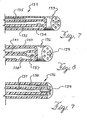
- the nebulizing catheter 132 may be either a stand alone-type of nebulizing catheter, or may be incorporated into an endotracheal tube either removably, as in FIGS. 1 - 5, or non-removably.
- the tip 133 of the catheter 132 is formed with a plurality of lumens terminating in a plurality of orifices.
- An inner lumen 134 is used to convey the liquid medication and the surrounding lumens 135 convey the pressurized gas used to nebulize the liquid.
- This embodiment has the advantage that the orifice of the liquid lumen 134 is centered with a fixed spacing relative to the orifices of the gas lumens 135 around it. In the embodiment of FIG.
- the multiple lumen construction may extend all the way back to the proximal end of the nebulizing catheter 132 or alternatively, only a distal segment may have the multiple gas lumen configuration in which case the pressurized gas may be conveyed through a single proximal lumen that connects to the multiple distal lumens.
- FIGS. 8 and 9 show an alternative embodiment 136 of the multiple lumen nebulization catheter in FIG. 7.
- the embodiment in FIGS. 8 and 9 is useful when it is desired to provide the aerosol medicine with a pulsed delivery.
- the pulsed delivery may be timed to coincide with the inhalation of the patient so that aerosol is not wasted when the patient is exhaling.
- a potential drawback with pulsed delivery is that the aerosol may drool from the tip of the nebulizing catheter when the pressure being applied to the liquid is reduced to effect the pulsation.
- the nebulizing catheter 136 provides for closure of the liquid lumen when the pressure being applied to it is reduced.
- the catheter 137 has a centrally located lumen 137 for delivery of a liquid medicine and a plurality of lumens 138 surrounding the central lumen 137 for conveyance of a pressurized gas to nebulize the liquid at the distal orifice 139.
- the catheter 137 is formed of a low compliance material in the outer wall area 140 and a relatively high compliance material in the area 141 surrounding the centrally located liquid lumen 137. These differing compliance characteristics may be formed in the catheter shaft by coextruding a single tube with different materials.
- a constant, relatively high pressure is applied to the gas in the lumens 138.
- Liquid medicine is delivered via the lumen 137 and pressure pulses are applied to the liquid from an external delivery source, such as a pump.
- an external delivery source such as a pump.
- the high pressure in the gas lumens 138 deform the compliant inner material 141 thereby compressing the liquid lumen 137 and closing it off, as shown in FIG. 8.
- a pressure pulse is applied to the liquid in the lumen 137, it overcomes the compressive forces from the gas lumens 138 allowing the lumen 137 to open and permitting the liquid medicine to be delivered to the distal orifice 139 to be nebulized, as shown in FIG. 9.
- the embodiment of FIGS. 8 and 9 provides for pulsed liquid nebulization with reduced possibility of drooling.
- FIGS. 8 and 9 Another feature shown in FIGS. 8 and 9 is a porous plug located in the liquid orifice 139.
- This porous plug may be made of a felt-like material and may assist in the production of fine aerosol particles.
- FIG. 10 shows a distal tip of another embodiment of the nebulizing catheter.
- a nebulizing catheter 148 includes. a main shaft section 152 and a distal shaft section 156.
- the distal shaft section 156 is tapered to a tip 160.
- a liquid orifice 164 is surrounded by a plurality of gas orifices 168.
- the liquid orifice 164 has a diameter of approximately .002 inches and the gas orifices 168 each have a diameter of approximately .002 inches.
- This embodiment is similar to the embodiment of FIG. 7 except that the distal section 156 provides for a reduction in the tip size and corresponding modification of the nebulization plume properties. This reduction is preferable as it provides a smaller orifice size.
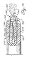
- FIG. 11 shows a distal portion of a nebulizing catheter 172.
- the nebulizing catheter includes a proximal shaft section 176 and a distal shaft section 180.
- the proximal shaft section 176 includes a plurality of lumens 184.
- a central one 188 of the plurality of lumens 184 is used to convey liquid medicine and the remainder of the lumens surrounding it are used to convey gas.
- the distal shaft section 180 connects to the distal end of the proximal shaft section 176 and defines a tapered cavity 192 between the distal end of the proximal shaft section 176 and a distal orifice 196.
- At least one of the plurality of lumens 184 is used to convey a pressurized gas that is discharged into the cavity 192.
- a tubular extension 200 extends the liquid lumen through the cavity 192 and distally out the orifice 196.
- the orifice 196 is sized to provide an annular region around the tubular extension 200 to permit the pressurized gas to flow through to nebulize the liquid medication that exits a distal orifice 204 of the tubular extension 200.
- the distal shaft section 180 is composed of stainless steel and the orifice has an I.D. of 0.635 mm (0.025 inches).
- the tubular extension 200 has an O.D. of 0.305 mm (0.012 inches) and an I.D. of 0.178 mm (0.007 inches).
- This embodiment has the advantage of combining a relatively small distal profile with a relatively large proximal flow channel. Another advantage of this embodiment it that it provides for a balanced airflow around the liquid orifice 204.
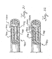
- FIG. 12 shows yet another tip for a nebulizing catheter.
- a nebulizing catheter 208 is shown for convenience having a coaxial configuration although it could also have a configuration similar to that of FIGS. 7, 10, or 11.
- a thin solid wire or filament 212 is located at a distal end of a liquid orifice 216 located at a distal end of an inner tubular member 220.
- the tapered wire 212 extends a short distance distally from the distal end of the inner tubular member 220.
- the tapered wire 212 is located with respect to the liquid orifice 212 so that liquid being conveyed through the inner member 220 continues to flow distally of the distal orifice 216 along the wire 212, i.e.
- the liquid reaches a distal tip 224 of the wire 212, it is entrained and nebulized by the gas flow from the annular region 228 defined between the inner tubular member 220 and an outer tubular member 232.
- the size of the distal liquid orifice In general, a smaller liquid orifice produces smaller particles and a narrow aerosol plume cone.
- the thin wire 212 carries only a small amount of liquid along it so that it functions similarly to an orifice of a very small size. Accordingly, the embodiment of FIG. 12 has the potential for producing an aerosol of very fine particles.
- the outer tubular member has an I.D. of approximately 0.508 mm (0.020 inches).
- the inner tubular member has an I.D. of approximately 0.152 mm (0.006 inches).
- the thin wire has an O.D. of approximately 0.051 mm (0.002 inches).
- the wire or filament 212 may be composed of a metal wire or a polymer wire, such as a polyolefin fiber like Spectra fiber.
- the filament 212 may be composed of a porous or felt-like material, such as nylon or Porex, in which case it may be wider in diameter than if made of a solid material.
- FIG. 13 shows an alternative catheter in which there is a distal end of a nebulizing catheter 236 having a tapered wire or filament 240 located at the distal end of a lumen of an inner tubular member 244.
- the tapered wire 240 in this embodiment has a curved shape that is designed to whip in a spiral when it is in a flow of air.
- the length of the wire 240 is chosen so that it does not impact the wall of the trachea or other airway passage when it moves in a spiral whipping motion.
- the wire 240 has a length of approximately 1 - 2 mm.
- the tapered wire 240 carries the liquid out to its tip for entrainment, and the nebulization plume is formed with a conical shape.
- the width of the plume may be changed by changing the length of the filament 240.
- the speed of the spiral motion can be controlled by appropriate selection of wire stiffness and air foil shape.
- the spiral plume produced by the catheter of FIG. 13 will be wider than that of the catheter of FIG. 12 and have less forward velocity. Both these characteristics may be favored in a nebulization catheter.
- FIG. 14 shows an alternative nebulization catheter 340 having an additional lumen 365.
- This additional lumen 365 may have an I.D. of approximately 0.508 mm (0.020 inches).
- This additional lumen 365 may be used for an optical fiber viewing scope 366 for illumination and visualization of the distal end of the nebulization catheter 340.
- the optical viewing scope 366 may be permanently installed in the catheter 340 or preferably may be removable.
- a distal end 367 of the lumen 365 is open or covered with a transparent lens so that the area distal of the catheter 340 can be observed via an optical viewing device connected to a proximal end of the optical fiber 366.
- the gas orifice 356 may be located so that the pressurized gas that is expelled helps to keep the distal end of the viewing lumen 365 clear.
- An optical fiber viewing channel may be incorporated into any of the nebulization catheters disclosed herein. When the additional lumen 365 is occupied by a removable viewing scope, it may be used for other purposes such as pressure sensing, gas sampling, over pressure relief, or other diagnostic or therapeutic purposes. Alternatively, another lumen may be provided for these purposes.
- the catheter of FIG. 14 also shows opposing orifices.
- a tubular extension 360 extends distally of the end of the catheter shaft and is oriented at an angle, e.g. 90 degrees, to the direction of the axis if the catheter shaft.
- the tubular extension 360 opens to a distal liquid orifice 364 from which the liquid being conveyed in the lumen 352 exits.
- a second tubular extension 363 communicates with the gas lumen 348 and opens to a distal gas orifice 367.
- the second tubular extension 363 is also oriented relative to the axis of the catheter shaft, e.g. by 90 degrees, so that is aimed toward the distal liquid orifice 364 in order to nebulize the liquid exiting from the liquid orifice 367.
- the position of the nebulization catheter relative to the anatomical environment is the position of the nebulization catheter relative to the anatomical environment.
- the delivery efficiency of the catheter may be significantly impaired if the plume is directed into the wall of the endotracheal tube, the trachea or other airway passage.
- proper location, orientation, and alignment of the nebulization catheter in the anatomy can be an important factor contributing the delivery of medicine via a nebulization catheter.
- an endotracheal tube if present, can adversely effect delivery of aerosol from a separate nebulization catheter.
- an endotracheal tube has an inner diameter that is smaller than the diameter of the trachea so that if the nebulization takes place inside the endotracheal tube, a portion of the aerosol may impact the inner wall of the endotracheal tube and thereby be wasted.
- Most conventional endotracheal tubes have a curved distal end that is relatively rigid so that when it is in place in the trachea of a patient, the distal end of the endotracheal tube is oriented off center.
- nebulization catheter located in the endotracheal tube causing it direct its aerosol into the trachea wall even if the nebulization catheter is positioned so that its distal end is located distally of the endotracheal tube.
- aerosol particles it is desirable to allow the aerosol particles to avoid impaction for several centimeters after the aerosol is produced so that the aerosol particles can lose their velocity and become entrained in the inspiratory airflow.
- the catheter in FIG. 15 is directed at providing improved alignment of a nebulization catheter in a patient's trachea.
- an endotracheal tube 700 is positioned in a trachea 704 of a patient.
- the endotracheal tube 700 is of a type that has an inflatable cuff 708 located around a distal exterior side to facilitate positioning and alignment of the endotracheal tube 700 in the trachea 696.
- Extending through and out of a distal end of the endotracheal tube 700 is a nebulization catheter 712.
- the nebulization catheter 712 may be similar to any of the embodiments of the nebulization catheter described above.
- the spring centering apparatus 720 includes a retainer ring 724 fixed to the shaft of the nebulization catheter 712 and a plurality of arms 728 connected to the ring 724. In one embodiment, there are three arms 726. The arms 726 are flexible and resilient. The arms 726 may be made of a spring tempered metal or a suitable plastic. Located at the end of each of the arms 726 opposite its connection to the ring 724 is a ball 727. The spring centering apparatus 720 is deployed by first positioning the nebulizing catheter 712 including the spring centering apparatus in the lumen 728 of the endotracheal tube 700.
- the arms 726 are formed so that they assume a size larger than the diameter of the trachea or airway passage. Accordingly, when the centering device is positioned in the endotracheal tube 700, the arms are resiliently deformed into a compressed configuration with the balls 727 close to the shaft of the nebulizing catheter 712. To deploy the centering device, the nebulizing catheter 712 is advanced out the distal end of the endotracheal tube 700. When the balls 727 are advanced out the endotracheal tube 700, they spring out to an expanded size and engage the walls of the trachea or other airway passage. The balls 727 provide a relatively smooth surface to limit irritation or injury to the trachea walls or other airway passage.
- the nebulizing catheter With the arms expanded, the nebulizing catheter is centered in the trachea or other airway passage so that a plume discharged from a distal end of the nebulizing catheter has minimal contact with the walls of the trachea or other airway passage.
- the arms are formed of a thin resilient wire or polymer, preferably less than approximately 0.381 mm (0.015 inches) in diameter.
- the arms and/or the balls may be made of, or coated with, a radiopaque material. It is an advantage of the centering device shown in FIG.
- the centering device orients the distal tip of the nebulization catheter relative to the portion of the trachea or other airway passage beyond the distal tip thereby helping to reduce impaction along this portion.
- FIG. 16 shows an alternative nebulization catheter 729 which is used with an endotracheal tube as described above.
- the nebulization catheter 729 includes a centering device 730.
- the centering device 730 includes a plurality of arms 731 that are formed to resiliently extend outward from the axis of the catheter shaft to engage the wall of the patient's trachea or airway passage or the interior of an endotracheal tube depending upon the desired location of the distal end of the nebulization catheter.
- At the ends of each of the arms 731 are balls 732.
- the proximal ends of the arms 731 are formed of wires 733 that extend through lumens 734 in the shaft of the catheter 729.
- Each of the lumens 734 has a distal opening 735 from which an arm can extend.
- the distal openings are approximately 0.10 - 1.0 cm (0.004 to 0.039 inches) from the distal end of the catheter shaft.
- the proximal ends of the wires 733 exit the lumens 734 of the nebulization catheter via openings 736 that are close to the proximal end of the catheter in a portion of the catheter that would normally be outside the patient's body during use.
- the proximal ends of the wires 733 are accessible to the physician during use.
- the portion of the arms 731 that extend from the openings 735 can be adjusted.
- the arms 731 can be adjusted from a fully retracted to a fully advanced position by pulling or pushing on the proximal ends of the wires 733.
- the proximal ends can of the wires 733 be adjusted in any intermediate position between the fully retracted and fully advanced positions, the physician can adjust the size of the centering device 730 to any appropriate size, as desired.
- the wires 733 should assume a desired shape when advanced out of the lumens in which they are contained during positioning, it is preferable that they be formed of a material that has shape memory properties so that the desired expanded shape can be imparted to the wires during manufacture.
- the wires may be formed of nitinol.
- a second centering device 737 may also be provided.
- the second centering device 737 is located on the shaft of the nebulization catheter 729 proximally from the first centering device 730.
- the second centering device 737 may be formed of resilient wings formed of a material such as plastic or metal that extend radially outward from the shaft.
- the second (or proximal) centering device 737 helps keep the distal portion of the catheter 729 in alignment.
- FIG. 17 shows another alternative nebulizing catheter 738 which may be similar to the catheter 20 of FIG. 1.
- the nebulizing catheter 738 includes a centering device 739.
- the centering device 739 includes a wire loop 740 located at a distal end of the catheter.
- One end 741 of the loop 740 connects to the distal end of the nebulizing catheter shaft.
- the other end 742 of the wire loop 740 enters an opening 743 in the shaft that communicates with a lumen 744 that extends to a proximal end of the catheter 738.
- a proximal end 745 of the wire exits the lumen 744 via an opening 746 in a proximal portion of the nebulizing catheter which is normally outside the patient's body during use.
- the size of the wire loop 740 can be adjusted by advancing or withdrawing the proximal end 745 of the wire. In this arrangement it can be determined that the centering device is fully retracted when the wire 745 cannot be withdrawn any further.
- the position of the distal end of the nebulization catheter can also be determined by the resistance to further retraction caused when the loops or arms engage the distal end of the endotracheal tube.
- the wire loop 740 engages the walls of the trachea or airway passage or the interior of the endotracheal tube depending upon where the distal end of the nebulizing catheter is positioned.
- the size of the wire loop 740 can be adjusted from a fully reduced size to a fully expanded size as well as intermediate sizes.
- the size of the loop can be adjusted to different size airway passages in different patients or alternatively the size of the loops can be adjusted to different airway passages in the same patient if the physician desires relocating the nebulizing catheter to different locations in a patient's respiratory tract.
- More than one wire loop may be provided at the distal end of the nebulizing catheter. It is noted that the wire loop 740 may also be used in for facilitating positioning over a guide.
- FIGS. 18 and 19 show another alternative nebulizing catheter 747 having a shaft portion 748 and a wire loop 749 extending from a distal end of the shaft 748.
- the wire loop 749 is connected at each end 750 and 751 to the distal end of the catheter shaft 748.
- a retractable sheath 752 is positioned over the nebulizing catheter shaft 748. The sheath 752 can be advanced and withdrawn relative to the catheter shaft 748. When it is desired to maneuver the nebulizing catheter into a desired position in the respiratory tract of a patient, the sheath 752 is advanced over the loop 749 to maintain a low profile, as shown in FIG. 19.
- the sheath 752 is then retracted, as shown in FIG. 18, allowing the loop 749 to expand to its expanded size to center and align the distal end of the nebulizing catheter in the respiratory tract.
- the loop 749 may be formed of a superelastic material such as nitinol.
- nebulizing catheter 754 As noted above, proper positioning and alignment of the nebulization catheter can be an important factor affecting drug delivery efficiency. In general, it is preferable to position the tip of the nebulizing catheter as closely to the central region of the trachea (or other respiratory passage, such as the bronchi) as possible. It is further noted that even if the catheter can be centered relative to the trachea, if a section proximal to a centering device is misaligned, it can affect the directional orientation of the tip. This situation is represented in FIG. 20 in which a nebulizing catheter 753 is centered, but the tip is not properly aimed to provide an optimum plume. This potential problem can be overcome by using a nebulizing catheter 754 as shown in FIG.
- a first centering apparatus 757 is located on a main shaft 760 of the nebulizing catheter 754 close to the distal end 764.
- the first centering device 757 may be similar to the centering devices shown in FIGS. 15 - 19.
- a second centering device 768 is located axially along the nebulizing catheter shaft 760 proximally from the first centering device 757.
- the second centering device 768 may be the same as the first centering device 757. As shown in FIG.
- the two centering devices 757 and 768 not only serve to position the nebulization catheter 754 centrally in the trachea, but also serve to align the nebulizing catheter tip to expel the plume along a central axis of the trachea.
- the proximal centering device 768 may be substituted by another type of centering device or may employ the endotracheal tube 756 for this purpose, as shown in FIG. 23.
- the endotracheal tube may incorporate a distal, elongated occlusion cuff 772 or balloon to coaxially align it accurately in the trachea.
- Most conventional endotracheal tubes are provided with a curvature to facilitate positioning the trachea of a patient.
- most conventional endotracheal tubes are relatively stiff. These factors may result in the misalignment of the distal end of the endotracheal tube relative to a patient's trachea as illustrated in FIGS. 20 and 21.
- the tip of the endotracheal tube is straighter and/or more flexible than in conventional endotracheal tubes to ensure proper concentricity with the occlusion balloon and the trachea.
- An endotracheal tube with a straighter and more flexible tip is shown in FIG. 22.
- the endotracheal tube may be provided with a centering or aiming device 776 for aligning the nebulization catheter 754.
- the aiming device 776 is formed by a plurality of flexible or resilient wings the extend from the wall of the endotracheal tube 756 toward an axially central position.
- nebulization catheter Appropriate centering and aiming of the nebulization catheter can be affected by anatomical factors. It is noted that in some circumstances, it is preferable to position the distal tip of the nebulization catheter into either bronchus of the lungs or even into separate bronchia. Positioning of the nebulizing tip closer to the alveoli may enhance drug delivery efficiency. In a situation in which it is desired to place the nebulizer tip in both bronchi of the lungs, a nebulizing catheter 780 with dual tips can be employed, as shown in FIG. 23. When using a dual tip catheter such as shown in FIG. 23, centering and aiming can be important considerations because of the narrower air passages in each of the bronchi.
- each of the tips 784 and 788 may be provided with its own centering apparatus, such as 792 and 796.
- These centering devices may be similar to the centering devices described above.
- the centering devices 792 and 796 may be formed of arms or struts, made of a flexible or resilient material, that bow out from the shafts of each of the tips 784 and 788, as shown.
- These struts may be formed with a shorter length in order to fit into smaller airway passages or alternatively they may be made to provide a range of deployment sizes to accommodate different airway passages.
- a nebulizing catheter with dual tips 784 and 788 as shown in FIG. 23, if delivery of aerosolized medicine into separate branches of the lungs is desired, it may be preferred to use a nebulizing catheter with a single nozzle tip that has multiple orifices or jets aimed toward the desired branches.
- the centering devices are preferably constructed of wires or other materials having a small diameter or cross section to minimize losses due to such impaction.
- the overall improved efficiency due to the reduction in aerosol impaction on the walls of the trachea or other airway passage is expected to more than compensate for amy losses due to impaction on the centering device.
- Another alternative means for centering the distal end of a nebulization catheter in the air passage is to use part of the pressurized gas for a pneumatic centering device.
- Air jets generated from two or more outward directed orifices spaced evenly around the outer circumference of the nebulizing catheter near the tip can be used to center the catheter in the airway. This alternative may help avoid irritation and provide additional advantages compared to physical centering devices.
- Another alternative way to help center the nebulizing catheter in the patient's airway passage is to use a balloon or wire centering device placed near the nebulizing catheter tip.
- the balloon or wire centering device can be temporarily inflated to double check the placement of the nebulizing catheter tip in relation to the endotracheal tube tip.
- the nebulizing catheter is advanced beyond the endotracheal tube tip using markings on the proximal shaft to judge the distance.
- the centering device or balloon would then be expanded to a diameter larger than the endotracheal tube and the catheter retracted until the centering device or balloon could be felt engaging with the endotracheal tube tip or until the endotracheal airflow was obstructed.
- the driving gas used to pressurize the gas lumen may be pure (e.g. 100%) oxygen at a pressure of 241.32 - 344.74 kPa (35-50 psi). Other gases and pressures may be used with suitable adjustments to provide for the desired particle size.
- the pressurized gas also may be humidified by a bubbler or other suitable means and warmed, if necessary.
- one way to deliver the liquid drug through the nebulizing catheter is by a manually operated syringe.
- a syringe containing the liquid medicine to be nebulized is connected to the liquid port on the manifold connected to a proximal end of the nebulizing catheter. Then, the liquid is injected while the pressuring gas is being supplied to the nebulizing catheter via the gas inlet port on the nebulizing catheter manifold.
- a manually operated syringe is reliable, easy to use, and may be preferred when it is desired to deliver only a small amount of medication.
- the liquid drug is delivered to the nebulizing catheter from a pressurized source.
- a pressurized source for the liquid medicine can provide for a generally higher and more uniform pressure. A high pressure assists in clearing any blockages that may occlude the liquid lumen. Pressurization of the liquid lumen also can ensure that all the liquid drug is evacuated from the catheter tip.
- use of a liquid pressurization source can provide for drug delivery for a longer period of time or a drug delivery that is timed or pulsed to coincide with operation of a ventilator, if used.
- the same pressure source (at 344.74 kPa (50 psi)) that is used to provide the gas pressurization can also be used to provide for pressurization of the liquid.
- Some ventilators have an auxiliary port that are used for externally located nebulizers. The pressure flow from this auxiliary port may be used as a pressure source to drive the liquid and gas supplies of the embodiments of the nebulizing catheter considered herein.
- a sensor located in the flow from this auxiliary port may be used to trigger another control device that operates the pressurized liquid and gas supplies.
- the generation of the aerosol can be synchronized with the inhalation of the patient. In one embodiment, this can be accomplished with a manually operable control gas valve on the gas pressure line to the liquid input port. This may be suitable when the medicine can be delivered in a short period of time, e.g. a few respiratory cycles. Alternatively, when it is preferred to deliver the medicine for an extended period of time, it may be preferred to employ a system that can automatically deliver medicine via the nebulizer from a source of liquid medicine. In such a system, the gas and/or liquid flow are triggered by the patient's respiratory cycle with the use of an electronic pressure sensor and relay actuator.
- FIGS. 24 and 24 show several embodiments of a reservoir and pressurization system for use with a nebulizing catheter.
- a reservoir and pressurization assembly 800 is connected to a proximal end of a nebulization catheter.
- the nebulization catheter may be similar to any of the embodiments described above.
- the assembly 800 has a gas inlet port 804 that can connect to an external pressurized gas supply.
- the external pressurized gas supply may be the main gas supply of the hospital or may be provided by another unit.
- the external gas supply may provide oxygen at 344.74 kPa (50 psi).
- the gas inlet port 804 communicates with an airflow passageway 808 defined by and extending through the assembly 800.
- the assembly 800 includes a gas output port 812 that communicates with the fluid flow passageway 808 and which connects to a gas inlet port of the nebulization catheter (not shown).
- the gas output port 812 is located immediately downstream of the gas inlet port 804.
- Located in the fluid flow passageway 808 downstream of the gas outlet port 812 is a filter 816.
- the filter 816 is preferably a hydrophobic filter that allows the passage of gas but which would prevent the backflow of any liquid.
- an injection port and reservoir 820 Located downstream of the filter 816 in the fluid flow passageway 808 is an injection port and reservoir 820. This port 820 communicates with a supply of the liquid fluid medication to be supplied to the nebulizing catheter.
- the capillary tube reservoir 824 is comprised of a length of plastic tubing adapted to hold a supply of the liquid medication to be delivered.
- the capillary tube reservoir consists of a helical coil of transparent tubing.
- Located downstream of the capillary tubing reservoir 824 is a liquid outlet 828 that connects to a liquid inlet port of the nebulization catheter (not shown).
- the transparent capillary tubing 824 provides a convenient and reliable way to ascertain the supply of medication to the nebulizing catheter.
- the capillary tubing because of its length is capable of containing a suitable supply of the medication.
- the clear capillary tube allows easy visualization of the drug flow by watching the gas-drug meniscus travel down the tube.
- the capillary tubing may be used with an automatic detection device, e.g. a photocell, that provides an alarm to the medical personnel upon detection that the medication is running out in the capillary tubing or that the meniscus has ceased moving due to a blockage.
- a blockage may also be detected by detection of an increase in pressure.
- FIGS. 25 and 26 show another embodiment of a fluid reservoir and pressurization assembly 832.
- This embodiment includes a gas inlet 836, a fluid flow passageway 840, a liquid medicine supply vent 844, a filter 848, a capillary channel section 852, and an outlet port 856.
- the filter 848 is located downstream of the filling vent 844.
- the filter 848 allows the pressurized gas to push the liquid drug during use but prevents the liquid drug from backing up to the vent during filling.
- a second injection port 860 is provided downstream of the capillary section 852 and a second filter 864 is located downstream of the second injection port 860.
- the second filter 864 is preferably a filter having approximately a 20 ⁇ m retention.
- the capillary section 852 may be composed of a planar section 865.
- the planar section 865 may be a piece of plastic having a winding channel molded, routed or otherwise formed therein.
- the planar section 868 is preferably colored to provide suitable contrast with the liquid solution flowing therethrough.
- a transparent flat plastic cover is positioned over the winding channel of the planar section 865 to form the closed channel of the capillary section.
- the fluid channel in the capillary section preferably has an I.D. of approximately 2 mm (0.079 inches).
- the second inlet port 864 provides an additional means to add medication to the nebulizing catheter liquid flow.
- the gas is used to pressurize the tube and force the fluid to the catheter tip.
- the second filter 864 acts as a restrictive orifice to precisely meter the flow to the nebulizing catheter.
- the clear capillary channel allows easy visualization of the drug flow by watching the gas-drug meniscus travel down the tube.
- the narrow tube makes the flow appear to move quickly even at slow delivery rates. Thus, any flow interruption can be easily observed.
- the capillary tubing section also ensures that almost 100% of the drug is delivered to the catheter tip since there is no dead space in the line except at the injection port 860.
- FIG. 27 An embodiment of a flow delivery system for a nebulizing catheter incorporating humidification is shown in FIG. 27.
- a suitably large reservoir 866 holds sterile water or saline.
- the reservoir 866 is connected to the liquid supply lumen 867 of a nebulization catheter 868. Solution is drawn into the nebulization catheter 868 from the reservoir 866 by negative pressure at the catheter tip, gravity, a pump in the solution supply line distal of the reservoir, or by pressurizing the reservoir by a suitable means.
- Medicine may be added to the humidification water in at the following ways.
- the medicine is added to the isotonic saline in the solution reservoir 866 thereby providing for high dilution and slow, continuous delivery of the medicine along with the water.
- the medicine is introduced into the solution supply line 867 via an injection port 869 between the reservoir 866 and the liquid lumen of the catheter 868.
- the medicine may be delivered to the injection port of the solution supply line from a solution reservoir system such as system 800 of FIG. 24.
- a more concentrated dose of the medicine can be delivered at the specific time preferred by the physician.
- It may also be preferable to include a molecular sieve, check valve or air trap 870 between the reservoir 866 and the injection port to the to ensure that the medicine cannot flow or diffuse backwards into the reservoir 866.
- a heating element 871 may be associated with the liquid supply line 867 to the nebulizing catheter 868.
- This heating element 871 may include an electric coil wound around the supply line 867 or may use a heated water flow in a tubing wound around the supply line 867.
- the heating element 871 may be used in embodiments that provide for humidification as well as those that do not.
- the heating element 871 may be associated with the gas supply line or with the liquid reservoir 866.
- the nebulizing catheter It is generally considered preferable to operate the nebulizing catheter so as to generate an aerosol that is carried by a patient's inhalation to the lungs. This requires a pulsing of the aerosol generation so that it is timed to coincide with the inhalation of the patient. If the patient is intubated, the timing of the nebulization can be synchronized with the operation of the ventilator. It is recognized that it may be preferable to begin the nebulization slightly in advance of, at, or slightly after, the beginning of the inhalation period in order to account for the distance between the nebulization tip and the alveoli. Also, it may be preferable to stop the nebulization slightly before the end of the inhalation period in order to avoid wasting aerosol after the inhalation flow has stopped.
- FIGS. 28 and 29 show a portion of the flow control system for a nebulizing catheter.
- a flow line 876 has an inlet 880 and an outlet 884.
- the flow line 876 may be formed of a soft (e.g. compliant) tube.
- the inlet 880 connects to the source of liquid medicine and in particular may attach to the liquid outlet (828 or 856) of the liquid reservoirs shown in FIGS. 24 - 26.
- the flow line outlet 884 in FIGS. 28 and 29 connects to the liquid inlet port on the manifold of the nebulizing catheter, such as port 32 in FIGS. 1 and 2.
- the actuator piston 888 Located around a portion of the flow line 876 is an actuator piston 888.
- the actuator piston 888 includes a solenoid pinch valve 892 that can impinge upon the portion of the liquid flow line 876 extending therethrough thereby pinching it off.
- the actuator piston 888 is connected to and operated by a controller that receives input from the ventilator (such as from the auxiliary port used for an external nebulizer) so that the actuator piston 888 is operated to open and close the flow line synchronous with the inhalation and exhalation phases of the ventilator.
- a solenoid piston a metering valve or reversible syringe pump may be used.
- the flow control system 872 uses a. dual solenoid arrangement to provide a draw-back feature. Pulsing of the liquid flow by actuation of the actuator piston 888 may result in some liquid being left at the distal nebulizer liquid orifice when the pressure is turned off. This may result in small amounts of liquid drooling from the distal liquid orifice tip since the liquid is not being expelled under controlled pressure conditions. In order to limit the occurrence of such drooling, a draw back feature is provided in the flow control system. The draw back feature is provided by a second solenoid 896 which is associated with a bladder 900 that communicates with the flow line 876.
- the bladder 900 communicates with the flow control line 876 downstream of the actuator piston 888.
- the bladder is composed of an elastic material that is formed with a tendency to recover to an expanded size.
- the second solenoid 896 opens, as shown in FIG. 29.
- This allows the bladder 900 to resiliently recover to its expanded size, and when it does, it draws fluid into it from the fluid flow line 876. Because the fluid flow line 876 is closed proximally at the actuator piston 888, when the bladder draws fluid into it from the fluid flow line 876, it draws fluid from the distal end of the fluid flow line that connects to the nebulizing catheter liquid lumen. This causes the entire column of liquid in the liquid lumen of the nebulizing catheter to move slightly in a reverse direction (i.e. proximally) thereby moving the liquid away from the distal orifice. In this manner, the flow control system of FIGS. 28 and 29 allows the draw back of liquid in the flow line in a reverse direction during the exhalation phase of the ventilator when the liquid flow line is shut off.
- the medicine is carried by the inhalation of the patient.
- a number of factors affect the efficiency of the medicine delivered this way.
- the following embodiments are directed to improving drug delivery efficiency taking into account some of these factors.
- the ventilator may not provide a suitable interface.
- the ventilator may not provide sufficiently accurate information concerning the patient's respiration to enable the nebulization catheter to operate with highest efficiency. In such situations, it may be preferred to utilize one or more separate sensors to obtain information that can be used to trigger and operate the nebulization catheter.
- a nebulizing catheter 944 positioned in an endotracheal tube 948 located in the trachea 952 of a patient.
- a proximal end of the endotracheal tube 948 is connected to a ventilator 956.
- one or more sensors may be used.
- a first sensor 960 may be located on a distal end of the endotracheal tube 948.
- a sensor 964 may be positioned on the nebulization catheter 944.
- Another sensor 968 may be positioned on a separate device, such as a separate catheter 972 which is located further distally in the respiratory system.
- a sensor 976 may be positioned in the ventilator circuit of the ventilator 956 or in a ventilator auxiliary port, if available, or elsewhere on the patient.
- These sensors 960, 964, 968, and 976 may be types of sensors that measure pressure, flow or a physiological parameter of the patient, such as muscle contraction, electophysiological activity, etc. In alternative embodiments, one or more of these sensors may be used.
- FIGS. 31 and 32 show alternative embodiments of nebulization catheters that incorporate sensors.
- a nebulization catheter 980 is shown. This nebulization catheter 980 may be similar to the nebulization catheter in FIG. 7.
- a main shaft 984 includes a plurality of lumens with a centrally located lumen 988 used to deliver a liquid medicine and a plurality of lumens 992 located peripherally around it used to deliver a pressurized gas.
- One of the peripheral lumens 996 is not used for pressurized gas delivery, but instead is used for sensing purposes. This may be accomplished by forming an aperture 1000 through a wall of the main shaft 984. The aperture communicates with the sensing lumen 996.
- the aperture 1000 may be open or may be covered with a flexible diaphragm that permits transmission of pressure across it.
- a pressure sensing device may be located at a proximal end of the nebulizing catheter. The pressure at the distal end of the nebulizing catheter can be sensed by the proximally located sensing device via the sensing lumen 996. This could rely on pneumatic sensing of the distal air pressure. Because of the effect of the distal gas pressurization orifice, pressure sensing through the sensing lumen 996 may be used for purposes of gross overpressure for safety purposes. Alternatively, the pressure sensing lumen 996 may be used during periods of time when a pressurizing gas is not being delivered to sense the patient's physiological airway pressure.
- FIG. 32 shows another embodiment of a pressure sensing nebulization catheter.
- This embodiment is similar to the embodiment of FIG. 31 except that a sensor 1004 is located at a distal end of the catheter 980, specifically in the aperture 1000.
- the sensor 1004 is a pressure transducer.
- Wire leads 1008 extend proximally from the sensor 1004 via the lumen 996.
- the sensor 1004 could measure the flow at the distal end of the catheter. This may be accomplished by piezoelectric, optical, Hall effect, or other types of sensor technologies.
- the sensor may also be of a fiber optic type.
- FIGS. 31 and 32 show sensing apparatuses associated with a nebulization catheter, these same types of sensors could also be used in the endotracheal tube 948, the separate catheter 972, or the ventilator 956 of FIG. 30 or the ventilator circuit.
- the sensor outputs information to a controller 1012 that operates the flow control portion 1013 of the nebulization catheter system.
- the flow control portion may include the flow control assembly 872 (shown in FIG. 28) as well as include the control functions for gas pressurization.
- the controller 1012 may have preset triggering parameters or may be user adjustable.
- the controller 1012 may use airway flow, pressure, or physiological activity as a basis for controlling the flow control assembly 1013.
- the controller 1012 may provide for pulsing based upon any one of the following modes: (1) a controlled volume (bolus) of medicine is delivered with each pulse; (2) medicine is delivered until a physiological condition is sensed, e.g. exhalation; or (3) medicine is delivered for a fixable time interval, e.g. 2 seconds. These modes of operation may be selectable by the physician based upon the preferred treatment taking into account the patient's condition, the type of medicine being delivered, etc.
- one concern with delivery of an expanding gas is the cooling effect that it may have on the body. This can be a factor with high gas flow rates. Accordingly, it may be preferable to deliver aerosol on every other inhalation or every third inhalation, and so on. Alternatively, it may be preferred to deliver aerosol for certain periods of time, e.g. 5 minutes every hour. Therefore, by alternating aerosol delivery, the cooling effect associated with it can be reduced.
- nebulizing catheters have been described as being either adapted for use in conjunction with a separate endotracheal tube, or adapted to be used without an endotracheal tube. If used with an endotracheal tube, the embodiments of the nebulizing catheter disclosed above are preferably removable from the endotracheal tube if one is present. It is noted that many of the embodiments of the present invention disclosed herein may also be used in conjunction with a nebulization catheter that is non-removable from an endotracheal tube, i.e. in which the nebulizing catheter is incorporated into and forms part of the endotracheal tube.
- an endotracheal tube that provides for nebulized medication delivery is described in a patent application filed by Dr. Neil R. MacIntyre on March 10, 1992 entitled “Endotracheal Tube Adapted for Aerosol Generation at Distal End Thereof", the entire disclosure of which is incorporated herein by reference.
- an endotracheal tube that provides for nebulization of a medication at a distal end thereof.
- an endotracheal tube includes two additional, separate lumens, in addition to its main ventilation lumen used for the patient's breathing airflow.
- a medication in a liquid form is conveyed through one of the additional lumens and a pressurized gas is conveyed through the other lumen.
- the two additional lumens have distal openings near the distal end of the endotracheal tube airflow lumen.
- the distal opening of the pressurized gas lumen directs the pressurized gas across the distal medication lumen opening thereby nebulizing the liquid medication so that it can be delivered to the patient's lungs. It is intended that the present invention covers embodiments of nebulization catheters that are non-removable relative to an endotracheal tube.
- the nebulizing catheter can be incorporated into another device, such as an endotracheal tube, either removably or non-removably.
- Another such device into which a nebulizing catheter can be adapted is a suction or aspiration catheter.
- a suction catheter is sometimes used in conjunction with patients who are intubated.
- a suction catheter has an O.D. and a length such that it can be inserted through the ventilation lumen of an endotracheal tube.
- the suction catheter is used to aspirate fluids and mucin secretions that collect in the respiratory tract of in the endotracheal tube of a patient who is intubated.
- a conventional suction catheter is inserted down the ventilation lumen of the endotracheal tube and out the distal end.
- a mucolytic agent may be instilled as a liquid via a lumen of the suction catheter to help in the withdrawal of mucin from the trachea or bronchi.
- the suction catheter may then be withdrawn from the endotracheal tube and either disposed or retained in a sterile sheath connected to a proximal end of the endotracheal tube so that it can be reinserted into the endotracheal tube again.
- a nebulizing catheter can be incorporated into a suction catheter so that a single device can perform both the functions of aspiration and nebulization for aerosol delivery.
- the nebulizing catheter such as described above, could be incorporated into a suction catheter so that a single catheter can provide both functions. This could be accomplished by provided any of the embodiments of the nebulization catheter described above with a separate lumen for the purpose of providing a suction to withdraw fluid from a patient's respiratory tract. Combining the functions of a suction catheter and nebulization catheter into a single device has the advantages of avoiding the expense of separate products as well as avoiding the inconvenience of inserting and withdrawing separate devices.
- FIGS. 33 - 40 Suction catheters combined with a nebulization catheter are shown in FIGS. 33 - 40.
- FIGS. 33 - 37 show a suction catheter assembly 1220 including a suction catheter shaft 1222 slidably located inside of a flexible sheath 1224.
- a suction lumen 1225 extends through the suction catheter shaft 1222.
- a proximal manifold 1226 includes a port 1228 for connecting a vacuum source to the suction catheter lumen 1225.
- a valve 1230 operates to open and close the port 1228.
- a distal sleeve 1232 provides for connecting to an endotracheal tube such that the suction catheter shaft 1222 can be inserted into the endotracheal tube by pushing the proximal manifold 1226 toward the distal sleeve 1232.
- the distal sleeve 1232 may include a manifold for connection to a flush port 1233.
- a seal 1235 located in the sleeve 1232 closely bears on the suction catheter shaft to remove mucous or other unwanted materials that can be removed via the flush port 1233.
- the shaft of the suction catheter may be provided with a low friction, e.g. hydrophilic, coating to reduce adhesion of mucous.
- the suction catheter assembly 1220 includes two additional lumens 1234 and 1236. These lumens 1234 and 1236 are located in a wall of the suction catheter shaft 1222. These lumens 1234 and 1236 communicate with distal orifices 1238 and 1240 located at a distal end of the suction catheter shaft 1222. These lumens 1234 and 1236 are used to deliver a liquid medicine and a pressurized gas for nebulizing the liquid medicine, as described above. Also located at a distal end of the suction catheter shaft 1222 are suction openings 1242.
- the suction catheter assembly 1220 can be used in a conventional manner to remove mucin from the trachea and from the bronchi.
- the suction catheter assembly 1220 can also be used to deliver medicines to the lungs as an aerosol by means of the nebulizing lumens 1234 and 1236.
- the nebulizing lumens can also be used to deliver mucolytic agents as an aerosol. Because the fine aerosol delivered by the nebulizing lumens can be carried by a patient's inspiratory airflow into the bronchi, the mucolytic agent can be delivered further into bronchi compared to a suction catheter that merely instills or generates a coarse spray of a mucolytic agent.
- the flow velocity produced by the gas pressurization lumen may be used to assist in breaking up mucous at the end of the suction catheter.
- the suction catheter assembly 1220 When using the suction catheter assembly 1220, it can be positioned so that a distal end of the suction catheter shaft 1222 is close to the distal end of the endotracheal tube 1250 as shown in FIG. 35 or alternatively the suction catheter shaft 1222 can be positioned so that it extends past the distal end of the endotracheal tube 1250 as shown in FIG. 37. As shown in FIG. 37, the suction catheter shaft 1220 may be formed with a distal curvature so that the distal end can be brought into proximity with the tracheal wall.
- nebulizing lumens may be preferably in many situations to use a conventional suction catheter with a stand-alone nebulizing catheter.
- the stand-alone nebulizing catheter may be similar to any of the embodiments described above.
- a suction catheter and a nebulizing catheter can readily be used together with the alternative versions of the manifolds shown in FIGS. 38 - 40
- an endotracheal tube 1252 has a proximal end with a single port 1254.
- a suction catheter 1256 has a distal manifold 1258.
- the distal manifold 1256 could be formed as part of the suction catheter 1256 or could be provided as a separate component.
- the suction catheter manifold 1258 connects to the single port 1254 of the endotracheal tube 1252.
- the manifold 1258 has a first port 1260 for connecting to a ventilator and a second port 1264 for connecting to a proximal end of a nebulizing catheter 1266. As shown in FIG.
- the nebulizing catheter 1266 includes a sterile sheath 1268 which is similar to the sheath included on the suction catheter 1262.
- the suction catheter 1256 and the nebulizing catheter 1266 are positioned alternately inside the ventilation lumen of the endotracheal tube 1252. The suction catheter or the nebulizing catheter can be withdrawn temporarily and maintained in its sterile sheath while the other is being used.
- FIG. 39 there is shown another arrangement for connecting a suction catheter and nebulizing catheter to an endotracheal tube.
- a manifold 1270 connects to the proximal end of the endotracheal tube 1252.
- the manifold 1270 has port 1274 for receiving the nebulizing catheter 1266 and a second port 1276.
- a distal manifold 1278 of a suction catheter 1280 connects to the second port 1276.
- the suction catheter manifold 1278 has a port 1282 for connecting to the ventilator. This arrangement can be used similarly to the arrangement of FIG. 38.
- FIG. 40 shows still another arrangement for connecting a suction catheter and a nebulizing catheter to an endotracheal tube.
- the endotracheal tube 1252 is provided with a proximal end that includes dual ports.
- a first port 1284 receives the nebulizing catheter 1266.
- the second port 1286 may be connected to either directly to a ventilator or may be connected to a distal end of a suction catheter (not shown) in a conventional manner.
- the nebulizing catheter could be positioned down the suction lumen of the suction catheter.
- FIG. 41 shows another suction catheter also incorporating a nebulization of an aerosol.
- a suction catheter 1400 is extends from the ventilation lumen of an endotracheal tube 1250.
- the suction catheter 1400 includes distal suction orifices 1402 located close to the distal end of the suction catheter shaft.
- Located along the suction catheter shaft proximally of the suction orifices 1402 are one or more pairs of liquid and gas orifices 1404.
- the liquid and gas orifice pairs 1404 are located with respect to each other to produce an aerosol of the liquid being delivered to the liquid orifice as in the previous embodiments.
- the nebulization orifices 1404 are oriented radially from the suction catheter shaft to direct the aerosol delivered from the nebulization orifices 1404 toward the airway passage wall.
- the aerosol being delivered may be a mucolytic agent.
- the suction provided by the suction orifices draws the mucolytic agent delivered from the nebulization orifices as well as mucous treated by the mucolytic agent in a distal direction into the suction orifices 1402.
- FIG. 42 Another suction catheter with aerosol delivery is shown in FIG. 42.
- a suction catheter 1410 is located in a ventilation lumen of the endotracheal tube 1250.
- the suction catheter 1410 has a distal suction orifice 1412 for removing mucous from the airway passage.
- the suction catheter 1410 also includes distal gas and liquid orifices 1414 located in proximity to each other to produce a aerosol.
- the liquid and gas orifices are located in a distal extension 1416 of the suction catheter shaft so that they are distal of the suction orifice 1412.
- the liquid and gas nebulization orifices 1414 are oriented in a proximal direction toward the suction orifice 1412.
- the distal extension 1416 is formed to bring the nebulization orifices 1414 close to the wall of airway passage so that the aerosol delivered from the nebulization orifices 1414 washes the airway passage wall.
- the aerosol delivered may be a mucolytic agent to facilitate suctioning of the mucous out of the airway passage.
- the pressurized gas flow may be used to contribute to the dislodgement of mucous from the airway passage walls.
- nebulization catheter in which an aerosol is generated by directing a pressurized gas through a catheter near an orifice from which the liquid to be nebulized exits. It is considered to be within the scope of the invention described herein to use other means or agents to generate an aerosol for delivery of a medication to the respiratory tract.
- the above embodiments may be used in conjunction with devices that utilize other means to generate an aerosol of a liquid medication.
- a liquid delivered by a single liquid lumen may be nebulized by applying ultrasonic energy to the liquid, electrospray, steam, or a micropump similar to those used in ink jet type printers. These approaches to nebulization may be combined with pressurized gas to produce an aerosol of the liquid medication.
- nebulization catheter embodiments described herein could also be used in other types of nebulizers that are used externally of a patient's respiratory system, such as small volume nebulizers (SVN), humidification nebulizers, or nebulizers used for ocular or nasal drug administration.
- SVN small volume nebulizers
- humidification nebulizers humidification nebulizers
- nebulizers used for ocular or nasal drug administration.
- the embodiments of the nebulization catheter disclosed herein provide for a fine aerosol without the potential disadvantages of impacting the liquid on a baffle or recirculating the liquid medicine on a continuous basis which are common in such nebulizers.
Claims (29)
- Cathéter pour délivrer un médicament en aérosol aux poumons d'un patient, le cathéter comprenant:une tige de cathéter (132) comportant:une lumière de passage de liquide (134) située au centre de ladite tige et conçue pour transporter un médicament sous forme liquide;une pluralité de lumières de passage de gaz (135) situées sur la périphérie entourant ladite lumière de passage de liquide (134) et conçues pour transporter un gaz;un orifice distal de passage de liquide communiquant avec ladite lumière de passage de liquide (134); etune pluralité d'orifices distaux de passage de gaz communiquant avec ladite pluralité de lumières de passage de gaz (135), ladite pluralité d'orifices de passage de gaz étant alignée par rapport audit orifice distal de passage de liquide de façon à nébuliser un médicament liquide déchargé de l'orifice de passage de liquide.
- Cathéter selon la revendication 1, caractérisé en ce qu'au moins une partie (141) de ladite tige (136) entourant ladite lumière de passage de liquide (137) est formée à partir d'un matériau de faible complaisance de sorte que la régulation de débit au niveau dudit orifice distal de passage de liquide (139) d'un fluide délivré à travers ladite lumière de passage de liquide (137) est plus sensible à la régulation de débit à un emplacement qui lui est proximal.
- Cathéter selon la revendication 1 ou 2, caractérisé en outre en ce qu'il comprend une zone de pointe (160) formée par un cône dans l'extrémité distale du cathéter.
- Cathéter selon la revendication 3, caractérisé en ce que l'extrémité distale (156) du cathéter (148) présente la forme d'une zone de pointe (160) qui est conique de sorte que les lumières (164, 168) sont à proximité plus étroite les unes des autres à une extrémité distale de ladite zone de pointe (160) qu'à une extrémité proximale de la zone de pointe et/ou le diamètre interne respectif des lumières (164, 168) est plus petit à une extrémité distale de la zone de pointe (160) qu'à une extrémité proximale de la zone de pointe (160).
- Cathéter selon la revendication 3 ou 4, caractérisé en ce que six dits orifices de passage de gaz (168) entourent ledit orifice de passage de liquide (164); et six dites lumières de passage de gaz sont congruentes avec les six orifices de passage de gaz (168).
- Cathéter selon la revendication 3, 4 ou 5, caractérisé en ce que l'orifice de passage de liquide (164) a un diamètre d'approximativement 0,051 mm (0,002 pouce).
- Cathéter selon l'une quelconque des revendications 3 à 6, caractérisé en ce que chaque orifice de passage de gaz (168) a un diamètre de 0,051 mm (0,002 pouce).
- Cathéter selon la revendication 1, caractérisé par une section de tige proximale (176) et une section de tige distale (180); et une pluralité de lumières (184) dans ladite section de tige proximale (176).
- Cathéter selon la revendication 8, caractérisé en outre par:une extrémité distale de la section de tige proximale (176) raccordée à l'extrémité proximale de la section de tige distale (180);une cavité effilée (192) formée entre ladite extrémité distale de ladite section de tige distale (180) et ladite extrémité distale de ladite section de tige proximale;un orifice distal (196) situé à l'extrémité distale de la section de tige distale (180); etun prolongement tubulaire (200) prolongeant la lumière centrale, utilisé pour transporter un liquide à travers la cavité effilée (192) hors dudit orifice distal (196); etdans lequel ledit orifice distal (196) est dimensionné pour permettre l'écoulement de gaz dans une zone annulaire entourant le prolongement tubulaire (200) de façon à nébuliser le liquide qui sort de l'orifice distal du prolongement tubulaire.
- Cathéter selon la revendication 9, caractérisé en ce que l'orifice distal a un diamètre intérieur de 0,635 mm (0,25 pouce).
- Cathéter selon la revendication 9 ou 10, caractérisé en ce que le prolongement tubulaire a un diamètre extérieur de 0,305 mm (0,012 pouce) et un diamètre intérieur de 0,178 mm (0,007 pouce).
- Cathéter selon l'une quelconque des revendications 8 à 11, caractérisé en ce que la section de tige distale (180) est réalisée en acier inoxydable.
- Cathéter selon l'une quelconque des revendications précédentes, caractérisé par un fil effilé (212) situé par rapport à l'orifice de passage de liquide (216) de sorte que le liquide provenant de la lumière de passage de liquide continue de s'écouler distalement par rapport à l'orifice distal de passage de liquide (216) le long du fil (212).
- Cathéter selon la revendication 13, caractérisé en ce que le fil (240) présente une forme courbe de sorte que le gaz provenant des orifices de passage de gaz amène le fil à s'enrouler en fouettant en un mouvement spiralé.
- Cathéter selon la revendication 1, caractérisé en outre par un bouchon poreux (142) situé dans ledit orifice de passage de liquide (139).
- Cathéter selon l'une quelconque des revendications 1 à 12, caractérisé par un fil effilé ou filament (240) destiné à accroítre la largeur de l'aérosol.
- Cathéter selon la revendication 1, caractérisé par une lumière située en périphérie (996) qui est utilisée dans un but de détection.
- Appareil pour délivrer un médicament en aérosol aux poumons d'un patient, caractérisé en ce qu'il comprend un cathéter selon l'une quelconque des revendications précédentes:la tige de cathéter comportant une extrémité proximale et une extrémité distale;la lumière de passage de liquide communiquant à l'extrémité proximale avec un orifice (32) pour recevoir un médicament sous forme liquide;un appareil de régulation de débit raccordé à l'orifice (32), ledit appareil de régulation de débit comprenant:un conduit d'écoulement (876) communiquant avec l'orifice (32), ledit conduit d'écoulement étant occupé par le médicament; etune soupape (888) associée au conduit d'écoulement pour provoquer une délivrance pulsée de médicament à travers le conduit d'écoulement.
- Cathéter ou appareil selon l'une quelconque des revendications précédentes, caractérisé en ce qu'il comprend en outre une butée de sécurité (44) sur une partie proximale de la tige de cathéter.
- Cathéter ou appareil selon l'une quelconque des revendications précédentes, caractérisé en ce qu'il comprend en outre des repères gradués (41) sur ladite tige de cathéter.
- Cathéter ou appareil selon l'une quelconque des revendications précédentes, caractérisé en ce qu'il comprend en outre des raccords de type Luer sur les orifices proximaux communiquant avec lesdites lumières de passage de gaz et ladite lumière de passage de liquide.
- Cathéter ou appareil selon l'une quelconque des revendications précédentes, caractérisé en ce qu'il comprend en outre un filet (43) sur ladite tige de cathéter.
- Cathéter ou appareil selon l'une quelconque des revendications précédentes, caractérisé en ce que ladite tige de cathéter (340) comprend une lumière supplémentaire (368) s'étendant à travers elle; et
un scope à fibre optique (366) s'étendant à travers ladite lumière supplémentaire. - Cathéter d'aspiration devant être utilisé avec un tube endotrachéal, ledit cathéter d'aspiration étant dimensionné pour être reçu dans une lumière de ventilation du tube endotrachéal, ledit cathéter d'aspiration comportant une lumière d'aspiration pour retirer les glaires des voies respiratoires d'un patient intubé; ledit cathéter d'aspiration étant caractérisé en ce qu'il comprend en outre un cathéter de nébulisation selon l'une quelconque des revendications précédentes.
- Procédé de formation du cathéter selon l'une quelconque des revendications 3 à 7, le cathéter comportant des orifices distaux étroitement espacés, dimensionnés et espacés avec de petites tolérances, comprenant les étapes consistant à:prévoir un tube polymère extrudé à plusieurs lumières de taille relativement grande;chauffer une partie du tube à une température de transition dudit tube;étirer ladite partie de tube pour former une section conique avec un rapport d'étirage dans la plage comprise entre 2 sur 1 et 20 sur 1, de sorte que les lumières sont de plus en plus étroitement espacées dans ladite zone conique; etformer une pluralité d'orifices à une extrémité distale de ladite section conique, ladite pluralité d'orifices étant dimensionnée pour nébuliser un liquide délivré à travers l'une desdites lumières afin de former un aérosol avec un gaz délivré à travers les autres desdites lumières.
- Procédé selon la revendication 25, caractérisé en ce que l'étape consistant à former une pluralité d'orifices comprend en outre l'étape consistant à:couper une extrémité distale de la section conique.
- Procédé selon la revendication 25, caractérisé en outre par l'étape consistant à couper le tube à dimension pour former une partie de tige du cathéter de nébulisation.
- Procédé selon la revendication 25, caractérisé en outre par l'étape consistant à exposer une partie dudit tube à un rayonnement d'énergie élevée.
- Procédé selon la revendication 25, caractérisé en ce que l'étape de chauffage comprend en outre l'étape consistant à chauffer le tube à une température entre un état de fusion et un état vitreux dudit tube.
Priority Applications (1)
| Application Number | Priority Date | Filing Date | Title |
|---|---|---|---|
| EP04008334A EP1433493B1 (fr) | 1994-06-17 | 1995-06-19 | Cathéter comprenant un dispositif de nébulisation |
Applications Claiming Priority (2)
| Application Number | Priority Date | Filing Date | Title |
|---|---|---|---|
| US26186694A | 1994-06-17 | 1994-06-17 | |
| US261866 | 1994-06-17 |
Related Child Applications (1)
| Application Number | Title | Priority Date | Filing Date |
|---|---|---|---|
| EP04008334A Division EP1433493B1 (fr) | 1994-06-17 | 1995-06-19 | Cathéter comprenant un dispositif de nébulisation |
Publications (2)
| Publication Number | Publication Date |
|---|---|
| EP0692273A1 EP0692273A1 (fr) | 1996-01-17 |
| EP0692273B1 true EP0692273B1 (fr) | 2004-04-07 |
Family
ID=22995221
Family Applications (2)
| Application Number | Title | Priority Date | Filing Date |
|---|---|---|---|
| EP95304223A Expired - Lifetime EP0692273B1 (fr) | 1994-06-17 | 1995-06-19 | Cathéter comprenant un dispositif de nébulisation et son procédé de fabrication |
| EP04008334A Expired - Lifetime EP1433493B1 (fr) | 1994-06-17 | 1995-06-19 | Cathéter comprenant un dispositif de nébulisation |
Family Applications After (1)
| Application Number | Title | Priority Date | Filing Date |
|---|---|---|---|
| EP04008334A Expired - Lifetime EP1433493B1 (fr) | 1994-06-17 | 1995-06-19 | Cathéter comprenant un dispositif de nébulisation |
Country Status (13)
| Country | Link |
|---|---|
| US (3) | US5964223A (fr) |
| EP (2) | EP0692273B1 (fr) |
| JP (3) | JP3746090B2 (fr) |
| KR (1) | KR960000256A (fr) |
| AT (2) | ATE263595T1 (fr) |
| AU (1) | AU700225B2 (fr) |
| BR (1) | BR9502836A (fr) |
| CA (1) | CA2152002C (fr) |
| DE (1) | DE69532843T2 (fr) |
| IL (1) | IL114154A0 (fr) |
| NZ (1) | NZ272354A (fr) |
| RU (1) | RU2141351C1 (fr) |
| ZA (1) | ZA954936B (fr) |
Cited By (23)
| Publication number | Priority date | Publication date | Assignee | Title |
|---|---|---|---|---|
| WO2005042079A1 (fr) * | 2003-10-31 | 2005-05-12 | Trudell Medical International | Systeme et methode de manipulation d'un catheter afin d'introduire une substance dans une cavite corporelle |
| US7704223B2 (en) | 2003-10-07 | 2010-04-27 | Northgate Technologies Inc. | System and method for delivering a substance to a body cavity |
| US8136527B2 (en) | 2003-08-18 | 2012-03-20 | Breathe Technologies, Inc. | Method and device for non-invasive ventilation with nasal interface |
| US8381729B2 (en) | 2003-06-18 | 2013-02-26 | Breathe Technologies, Inc. | Methods and devices for minimally invasive respiratory support |
| US8418694B2 (en) | 2003-08-11 | 2013-04-16 | Breathe Technologies, Inc. | Systems, methods and apparatus for respiratory support of a patient |
| US8567399B2 (en) | 2007-09-26 | 2013-10-29 | Breathe Technologies, Inc. | Methods and devices for providing inspiratory and expiratory flow relief during ventilation therapy |
| US8663271B2 (en) | 2006-08-04 | 2014-03-04 | Northgate Technologies, Inc. | In-dwelling port for access into a body |
| US8677999B2 (en) | 2008-08-22 | 2014-03-25 | Breathe Technologies, Inc. | Methods and devices for providing mechanical ventilation with an open airway interface |
| US8770193B2 (en) | 2008-04-18 | 2014-07-08 | Breathe Technologies, Inc. | Methods and devices for sensing respiration and controlling ventilator functions |
| US8776793B2 (en) | 2008-04-18 | 2014-07-15 | Breathe Technologies, Inc. | Methods and devices for sensing respiration and controlling ventilator functions |
| US8876791B2 (en) | 2005-02-25 | 2014-11-04 | Pulmonx Corporation | Collateral pathway treatment using agent entrained by aspiration flow current |
| US8925545B2 (en) | 2004-02-04 | 2015-01-06 | Breathe Technologies, Inc. | Methods and devices for treating sleep apnea |
| KR20150004832A (ko) * | 2012-04-23 | 2015-01-13 | 키에시 파르마슈티시 엣스. 피. 에이. | 분무화에 의한 폐계면활성제의 투여를 위한 방법 및 시스템 |
| US8939152B2 (en) | 2010-09-30 | 2015-01-27 | Breathe Technologies, Inc. | Methods, systems and devices for humidifying a respiratory tract |
| US8955518B2 (en) | 2003-06-18 | 2015-02-17 | Breathe Technologies, Inc. | Methods, systems and devices for improving ventilation in a lung area |
| US8985099B2 (en) | 2006-05-18 | 2015-03-24 | Breathe Technologies, Inc. | Tracheostoma spacer, tracheotomy method, and device for inserting a tracheostoma spacer |
| US9032951B2 (en) | 2010-08-24 | 2015-05-19 | Trudell Medical International | Aerosol delivery device |
| US9132250B2 (en) | 2009-09-03 | 2015-09-15 | Breathe Technologies, Inc. | Methods, systems and devices for non-invasive ventilation including a non-sealing ventilation interface with an entrainment port and/or pressure feature |
| US9180270B2 (en) | 2009-04-02 | 2015-11-10 | Breathe Technologies, Inc. | Methods, systems and devices for non-invasive open ventilation with gas delivery nozzles within an outer tube |
| US9572595B1 (en) | 2014-03-05 | 2017-02-21 | Northgate Technologies Inc. | In-dwelling port for access into a body |
| US10143814B2 (en) | 2011-03-29 | 2018-12-04 | Teleflex Life Sciences Unlimited Company | Fluid input module for multi-lumen catheters |
| CN109152890A (zh) * | 2016-03-02 | 2019-01-04 | 克劳斯贝医疗有限公司 | 一种回声导管系统的方法和装置 |
| US11452831B2 (en) | 2016-01-06 | 2022-09-27 | Airway Medix S.A. | Closed suction system |
Families Citing this family (326)
| Publication number | Priority date | Publication date | Assignee | Title |
|---|---|---|---|---|
| US6676627B1 (en) * | 1990-08-06 | 2004-01-13 | Possis Medical, Inc. | Crossflow thrombectomy catheter and system |
| US5642730A (en) * | 1994-06-17 | 1997-07-01 | Trudell Medical Limited | Catheter system for delivery of aerosolized medicine for use with pressurized propellant canister |
| US6729334B1 (en) * | 1994-06-17 | 2004-05-04 | Trudell Medical Limited | Nebulizing catheter system and methods of use and manufacture |
| IL114154A0 (en) * | 1994-06-17 | 1995-10-31 | Trudell Medical Ltd | Nebulizing catheter system and methods of use and manufacture |
| SE9503141D0 (sv) * | 1995-09-12 | 1995-09-12 | Siemens Elema Ab | Narkosapparat |
| FR2758089B1 (fr) * | 1997-01-06 | 1999-03-05 | Georges Boussignac | Procede et dispositif pour echanger des sondes respiratoires dans la trachee d'un patient |
| US6491940B1 (en) | 1999-01-27 | 2002-12-10 | Bruce H. Levin | Apparatus for administering composition for inhibiting cerebral neurovascular disorders and muscular headaches |
| US6432986B2 (en) | 1997-07-21 | 2002-08-13 | Bruce H. Levin | Compositions, kits, and methods for inhibiting cerebral neurovascular disorders and muscular headaches |
| US7799337B2 (en) | 1997-07-21 | 2010-09-21 | Levin Bruce H | Method for directed intranasal administration of a composition |
| US6016800A (en) * | 1997-10-24 | 2000-01-25 | Century; Theodore J. | Intrapulmonary aerosolizer |
| US6167883B1 (en) * | 1998-01-23 | 2001-01-02 | Respiratory Support Products, Inc. | Medical air hose internal flow heater |
| EP2289423A1 (fr) * | 1998-05-14 | 2011-03-02 | David N. Krag | Système pour l'encadrement d'un tissu |
| US6319248B1 (en) * | 1998-07-29 | 2001-11-20 | Cryocath Technologies, Inc. | Spray catheter |
| SE512807C2 (sv) * | 1998-09-02 | 2000-05-15 | Bjoern Flodin | Anordning för tillförsel av inandningsgas till och bortförsel av utandningsgas från en patient |
| US6855123B2 (en) | 2002-08-02 | 2005-02-15 | Flow Cardia, Inc. | Therapeutic ultrasound system |
| US8506519B2 (en) | 1999-02-16 | 2013-08-13 | Flowcardia, Inc. | Pre-shaped therapeutic catheter |
| US7018365B2 (en) | 1999-05-21 | 2006-03-28 | Micro Therapeutics, Inc. | Threaded syringe with quick stop |
| US6415788B1 (en) * | 1999-07-02 | 2002-07-09 | Enternet Medical, Inc. | Apparatus for treating respiratory gases including liquid trap |
| US6976489B2 (en) | 2000-06-30 | 2005-12-20 | Northgate Technologies, Inc. | Method and apparatus for humidification and warming of air |
| CA2408984C (fr) | 2000-06-30 | 2011-08-16 | Peter A. Manzie | Procede et appareil permettant d'humidifier et de rechauffer l'air |
| US6464662B1 (en) | 2000-07-26 | 2002-10-15 | Image-Guided Neurologics, Inc. | Drug delivery and catheter systems, apparatus and processes |
| US6536423B2 (en) * | 2000-08-14 | 2003-03-25 | Patrick J Conway | Patient activated mouth moisturizer |
| FR2813197B1 (fr) | 2000-08-22 | 2003-08-08 | Georges Boussignac | Dispositif d'assistance respiratoire avec des administration de produits nebulises |
| US6706017B1 (en) * | 2000-09-18 | 2004-03-16 | Pavel Dulguerov | Percutaneous ostomy device and method for creating a stoma and implanting a canula |
| AU2002236549B2 (en) * | 2000-11-03 | 2005-11-10 | The Cleveland Clinic Foundation | Catheter for removal of solids from surgical drains |
| EP2130511A1 (fr) * | 2000-11-17 | 2009-12-09 | Calypso Medical, Inc | Système de localisation et définition d'une cible intérieure au corps humain |
| US8235919B2 (en) | 2001-01-12 | 2012-08-07 | Celleration, Inc. | Ultrasonic method and device for wound treatment |
| US6517492B2 (en) * | 2001-02-22 | 2003-02-11 | Texon Technologies Ltd. | Method and apparatus for assessment of cardiac function by monitoring movement of the trachea |
| US20020132013A1 (en) * | 2001-03-14 | 2002-09-19 | Harry Moulis | Liquid cautery catheter |
| WO2002083222A1 (fr) * | 2001-04-11 | 2002-10-24 | Michael Kandler | Dispositif pour la respiration artificielle |
| US6905489B2 (en) * | 2001-04-24 | 2005-06-14 | Northgate Technologies, Inc. | Laparoscopic insertion device |
| US20030051733A1 (en) | 2001-09-10 | 2003-03-20 | Pulmonx | Method and apparatus for endobronchial diagnosis |
| US7883471B2 (en) | 2001-09-10 | 2011-02-08 | Pulmonx Corporation | Minimally invasive determination of collateral ventilation in lungs |
| US20050245944A1 (en) * | 2002-02-01 | 2005-11-03 | Rezai Ali R | Apparatus for facilitating delivery of at least one device to a target site in a body |
| FR2836384B1 (fr) | 2002-02-27 | 2004-12-10 | Georges Boussignac | Dispositif d'assistance respiratoire |
| US6698429B2 (en) * | 2002-03-15 | 2004-03-02 | Wolfe Tory Medical, Inc. | Medical atomizer |
| US7607436B2 (en) * | 2002-05-06 | 2009-10-27 | The Research Foundation Of State University Of New York | Methods, devices and formulations for targeted endobronchial therapy |
| US7334580B2 (en) * | 2002-05-07 | 2008-02-26 | Smaldone Gerald C | Methods, devices and formulations for targeted endobronchial therapy |
| JP4898223B2 (ja) * | 2002-05-07 | 2012-03-14 | ザ リサーチ ファウンデーション オブ ステイト ユニバーシティ オブ ニューヨーク | 標的化気管支内療法のための装置、および製剤 |
| US6918391B1 (en) * | 2002-05-20 | 2005-07-19 | Johnny V. Moore | Multi-lumen endotracheal tube |
| US20030226566A1 (en) * | 2002-06-06 | 2003-12-11 | Dhuper Sunil Kumar | Endotracheal tube with aerosol delivery apparatus II |
| US8074649B2 (en) * | 2002-07-18 | 2011-12-13 | Aeon Research And Technology, Inc. | Endotracheal tube with feature for delivering aerosolized medication |
| US9955994B2 (en) | 2002-08-02 | 2018-05-01 | Flowcardia, Inc. | Ultrasound catheter having protective feature against breakage |
| US8133236B2 (en) | 2006-11-07 | 2012-03-13 | Flowcardia, Inc. | Ultrasound catheter having protective feature against breakage |
| US7335180B2 (en) | 2003-11-24 | 2008-02-26 | Flowcardia, Inc. | Steerable ultrasound catheter |
| US7137963B2 (en) | 2002-08-26 | 2006-11-21 | Flowcardia, Inc. | Ultrasound catheter for disrupting blood vessel obstructions |
| US7220233B2 (en) | 2003-04-08 | 2007-05-22 | Flowcardia, Inc. | Ultrasound catheter devices and methods |
| US7604608B2 (en) | 2003-01-14 | 2009-10-20 | Flowcardia, Inc. | Ultrasound catheter and methods for making and using same |
| US6942677B2 (en) | 2003-02-26 | 2005-09-13 | Flowcardia, Inc. | Ultrasound catheter apparatus |
| ES2357566T3 (es) * | 2002-09-06 | 2011-04-27 | Philip Morris Usa Inc. | Dispositivos generadores de aerosol y métodos para generar aerosoles con tamaños de partículas controlados. |
| US7204248B2 (en) * | 2002-09-27 | 2007-04-17 | Cook Critical Care Incorporated | Fiberoptic nebulizer |
| IL152813A0 (en) * | 2002-11-13 | 2003-06-24 | Method and device for application of medical preparations to surfaces of the closed visceral cavities for example, to the pleura or the peritoneum | |
| US20040187864A1 (en) * | 2003-03-24 | 2004-09-30 | Cindet, Llc | Inhalation device and method |
| US20040193101A1 (en) * | 2003-03-25 | 2004-09-30 | Kimberly-Clark Worldwide, Inc. | Drain assembly for removing liquid from a gas directing tube |
| US20040193100A1 (en) * | 2003-03-25 | 2004-09-30 | Kimberly-Clark Worldwide, Inc. | Drain assembly with a piercing member for removing liquid from a gas directing tube |
| US7854724B2 (en) * | 2003-04-08 | 2010-12-21 | Surgiquest, Inc. | Trocar assembly with pneumatic sealing |
| US7654975B2 (en) * | 2003-04-24 | 2010-02-02 | Northgate Technologies, Inc. | Mixed-gas insufflation system |
| CA2565303C (fr) | 2003-05-02 | 2011-11-01 | Metolius Biomedical, Llc | Enlevement de debris d'un drain place dans un espace du corps |
| US6766801B1 (en) * | 2003-05-05 | 2004-07-27 | Medical Device Group, Inc. | Intra-tracheal aerosol delivery system and method of using same |
| US20040226556A1 (en) * | 2003-05-13 | 2004-11-18 | Deem Mark E. | Apparatus for treating asthma using neurotoxin |
| US8012136B2 (en) * | 2003-05-20 | 2011-09-06 | Optimyst Systems, Inc. | Ophthalmic fluid delivery device and method of operation |
| CA2526362C (fr) * | 2003-05-20 | 2012-10-09 | James F. Collins | Systeme de distribution de medicaments ophtalmiques |
| EP1636823A4 (fr) * | 2003-05-29 | 2007-11-21 | Upchurch Scient Inc | Appareil et procedes ameliores pour applications d'electronebulisation |
| US20060129091A1 (en) | 2004-12-10 | 2006-06-15 | Possis Medical, Inc. | Enhanced cross stream mechanical thrombectomy catheter with backloading manifold |
| US7892205B2 (en) * | 2003-06-06 | 2011-02-22 | Boston Scientific Scimed, Inc. | Device and method for delivering micronized therapeutic agents in the body |
| DE10337138A1 (de) | 2003-08-11 | 2005-03-17 | Freitag, Lutz, Dr. | Verfahren und Anordnung zur Atmungsunterstützung eines Patienten sowie Luftröhrenprothese und Katheter |
| US7758510B2 (en) | 2003-09-19 | 2010-07-20 | Flowcardia, Inc. | Connector for securing ultrasound catheter to transducer |
| US20130211320A1 (en) * | 2003-10-07 | 2013-08-15 | Nawar Alkhamesi | System and method for delivering an anti-adhesive substance to a body cavity |
| US20050089558A1 (en) * | 2003-10-28 | 2005-04-28 | Alamo Pharmaceuticals, Llc | Compositions and methods for the co-formulation and administration of tramadol and propoxyphene |
| US8210166B2 (en) * | 2003-12-16 | 2012-07-03 | Wolfe Tory Medical, Inc. | Vial multi-access adapter |
| US8182501B2 (en) | 2004-02-27 | 2012-05-22 | Ethicon Endo-Surgery, Inc. | Ultrasonic surgical shears and method for sealing a blood vessel using same |
| WO2005097250A1 (fr) * | 2004-03-30 | 2005-10-20 | Cook Urological Incorporated | Catheter d'irrigation |
| DE102004016985B4 (de) * | 2004-04-07 | 2010-07-22 | Pari Pharma Gmbh | Aerosolerzeugungsvorrichtung und Inhalationsvorrichtung |
| US7273050B2 (en) * | 2004-05-03 | 2007-09-25 | Huafeng Wei | Jet endotracheal device and its use in intubation |
| US7572244B2 (en) | 2004-08-02 | 2009-08-11 | Medrad, Inc. | Miniature cross stream thrombectomy catheter |
| US7847274B2 (en) * | 2004-08-12 | 2010-12-07 | Navotek Medical Ltd. | Localization of a radioactive source within a body of a subject |
| US7540852B2 (en) | 2004-08-26 | 2009-06-02 | Flowcardia, Inc. | Ultrasound catheter devices and methods |
| US8052592B2 (en) * | 2005-09-27 | 2011-11-08 | Evalve, Inc. | Methods and devices for tissue grasping and assessment |
| CA2581852C (fr) | 2004-09-27 | 2012-11-13 | Evalve, Inc. | Procedes et dispositifs de saisie et d'evaluation de tissus |
| EP3162309B1 (fr) | 2004-10-08 | 2022-10-26 | Ethicon LLC | Instrument chirurgical ultrasonique |
| EP1824545B1 (fr) * | 2004-10-15 | 2015-11-18 | Cook Medical Technologies LLC | Dispositif de blocage endobronchique a anse remplaçable |
| TR200403298A1 (tr) * | 2004-12-03 | 2006-02-21 | Kutluhan Ahmet | Mastoid antral ventilasyon tüpü |
| US8262605B2 (en) * | 2004-12-09 | 2012-09-11 | Ams Research Corporation | Needleless delivery systems |
| US8221343B2 (en) | 2005-01-20 | 2012-07-17 | Flowcardia, Inc. | Vibrational catheter devices and methods for making same |
| US7824436B2 (en) | 2005-05-13 | 2010-11-02 | Benechill, Inc. | Methods and devices for non-invasive cerebral and systemic cooling |
| US9358150B2 (en) | 2005-05-13 | 2016-06-07 | Benechill, Inc. | Methods and devices for non-invasive cerebral and systemic cooling alternating liquid mist/gas for induction and gas for maintenance |
| EP1922006A2 (fr) * | 2005-05-26 | 2008-05-21 | Smith & Nephew, Inc. | Traitement electrothermique de disque intervertebral |
| ITBO20050404A1 (it) * | 2005-06-15 | 2006-12-16 | Sherwood Serv Ag | Valvola di accesso broncotracheale per una apparecchiatura di broncoaspirazione |
| DE102005030803A1 (de) * | 2005-06-29 | 2007-01-11 | Boehringer Ingelheim Pharma Gmbh & Co. Kg | Verfahren und Vorrichtung zur Zerstäubung von Flüssigkeit |
| EP1896188B1 (fr) * | 2005-06-29 | 2010-08-18 | Boehringer Ingelheim International GmbH | Procede et dispositif d'atomisation de liquide |
| US8221348B2 (en) | 2005-07-07 | 2012-07-17 | St. Jude Medical, Cardiology Division, Inc. | Embolic protection device and methods of use |
| EP1906923B1 (fr) | 2005-07-22 | 2018-01-24 | The Foundry, LLC | Systemes et procedes d'administration d'un agent therapeutique |
| US7655243B2 (en) | 2005-07-22 | 2010-02-02 | The Foundry, Llc | Methods and systems for toxin delivery to the nasal cavity |
| US10052465B2 (en) | 2005-07-22 | 2018-08-21 | The Foundry, Llc | Methods and systems for toxin delivery to the nasal cavity |
| EP1924854B1 (fr) * | 2005-08-16 | 2016-04-13 | Oridion Medical 1987 Ltd. | Dispositif d'echantillonage de souffle et methode d'utilisation de celui-ci |
| US8116858B2 (en) * | 2005-08-22 | 2012-02-14 | John Koblanski | Methods and apparatus for monitoring heart motions |
| EP1932920A4 (fr) * | 2005-09-02 | 2009-04-08 | Eisai R&D Man Co Ltd | Methode pour detecter une substance efficace contre une maladie au moyen de gpr120 et de phospholipase |
| US7326183B2 (en) * | 2005-09-28 | 2008-02-05 | Alcon, Inc. | Intraocular pressure control |
| US20080188793A1 (en) | 2007-02-06 | 2008-08-07 | Possis Medical, Inc. | Miniature flexible thrombectomy catheter |
| US8012117B2 (en) * | 2007-02-06 | 2011-09-06 | Medrad, Inc. | Miniature flexible thrombectomy catheter |
| US8246642B2 (en) * | 2005-12-01 | 2012-08-21 | Ethicon Endo-Surgery, Inc. | Ultrasonic medical instrument and medical instrument connection assembly |
| US8523782B2 (en) | 2005-12-07 | 2013-09-03 | Pulmonx Corporation | Minimally invasive determination of collateral ventilation in lungs |
| US20070167965A1 (en) * | 2006-01-05 | 2007-07-19 | Ethicon Endo-Surgery, Inc. | Ultrasonic medical instrument |
| US7621930B2 (en) * | 2006-01-20 | 2009-11-24 | Ethicon Endo-Surgery, Inc. | Ultrasound medical instrument having a medical ultrasonic blade |
| US20070173872A1 (en) * | 2006-01-23 | 2007-07-26 | Ethicon Endo-Surgery, Inc. | Surgical instrument for cutting and coagulating patient tissue |
| US20070191712A1 (en) * | 2006-02-15 | 2007-08-16 | Ethicon Endo-Surgery, Inc. | Method for sealing a blood vessel, a medical system and a medical instrument |
| US7854735B2 (en) * | 2006-02-16 | 2010-12-21 | Ethicon Endo-Surgery, Inc. | Energy-based medical treatment system and method |
| US7766937B2 (en) * | 2006-03-13 | 2010-08-03 | Mini-Lap Technologies, Inc. | Minimally invasive surgical assembly and methods |
| US9282984B2 (en) | 2006-04-05 | 2016-03-15 | Flowcardia, Inc. | Therapeutic ultrasound system |
| US7909033B2 (en) | 2006-05-03 | 2011-03-22 | Comedica Incorporated | Breathing treatment apparatus |
| US20080004596A1 (en) * | 2006-05-25 | 2008-01-03 | Palo Alto Institute | Delivery of agents by microneedle catheter |
| EP2037999B1 (fr) | 2006-07-07 | 2016-12-28 | Proteus Digital Health, Inc. | Système d'administration parentérale intelligent |
| US8211052B1 (en) | 2006-07-13 | 2012-07-03 | Lexion Medical Llc | Charged hydrator |
| US8051854B2 (en) | 2006-09-15 | 2011-11-08 | Comedica Incorporated | Continuous high-frequency oscillation breathing treatment apparatus |
| US20080230053A1 (en) * | 2006-09-15 | 2008-09-25 | Board Of Regents, The University Of Texas System | Pulse drug nebulization systems, formulations therefore, and methods of use |
| US8012086B2 (en) * | 2006-10-19 | 2011-09-06 | Ethicon Endo-Surgery, Inc. | Sterile transcolonic access device |
| US7993071B2 (en) | 2006-10-25 | 2011-08-09 | Burrell E. Clawson | Assemblies for coupling two elements and coupled assemblies |
| US8246643B2 (en) | 2006-11-07 | 2012-08-21 | Flowcardia, Inc. | Ultrasound catheter having improved distal end |
| NZ625605A (en) * | 2006-11-08 | 2016-04-29 | Resmed Ltd | Conduit for use in a respiratory apparatus |
| US8991396B2 (en) * | 2006-11-09 | 2015-03-31 | The Board Of Trustees Of The University Of Illinois | Endotracheal tube with two ports |
| US20100286791A1 (en) * | 2006-11-21 | 2010-11-11 | Goldsmith David S | Integrated system for the ballistic and nonballistic infixion and retrieval of implants |
| US11833320B2 (en) | 2006-11-27 | 2023-12-05 | Frank Levy | Apparatus and process for producing CO2 enriched medical foam |
| US10350399B2 (en) | 2006-11-27 | 2019-07-16 | Frank Levy | Apparatus and method for producing an enriched medical suspension of carbon dioxide |
| US20190070397A1 (en) * | 2006-11-27 | 2019-03-07 | Frank Levy | Apparatus and method for producing co2 enriched medical foam |
| US10322271B2 (en) | 2006-11-27 | 2019-06-18 | Frank Levy | Delivery system and method for the effective and reliable delivery of controlled amounts of a medical fluid |
| US11185671B2 (en) | 2006-11-27 | 2021-11-30 | Frank Levy | Apparatus and process for producing CO2 enriched medical foam |
| US20080132757A1 (en) * | 2006-12-01 | 2008-06-05 | General Electric Company | System and Method for Performing Minimally Invasive Surgery Using a Multi-Channel Catheter |
| WO2008080153A2 (fr) * | 2006-12-22 | 2008-07-03 | The Children's Hospital Of Philadelphia | Nouvelle thérapie utilisant la protéine kinase c pour le traitement des blessures aiguës des poumons |
| US8491521B2 (en) * | 2007-01-04 | 2013-07-23 | Celleration, Inc. | Removable multi-channel applicator nozzle |
| US20100089404A1 (en) * | 2007-01-25 | 2010-04-15 | C.R. Bard,Inc. | Endotracheal and Tracheostomy Devices |
| JP2008199905A (ja) * | 2007-02-16 | 2008-09-04 | Snow Brand Milk Prod Co Ltd | 乳酸菌生残性向上剤 |
| DE202007003734U1 (de) * | 2007-03-14 | 2008-07-17 | Markus, Kai Ulf, Dr. | Mehrlumiger Mikrokatheter |
| US8057498B2 (en) | 2007-11-30 | 2011-11-15 | Ethicon Endo-Surgery, Inc. | Ultrasonic surgical instrument blades |
| US8911460B2 (en) | 2007-03-22 | 2014-12-16 | Ethicon Endo-Surgery, Inc. | Ultrasonic surgical instruments |
| US20090241948A1 (en) * | 2007-03-28 | 2009-10-01 | Dermot Joseph Clancy | Humidification in breathing circuits |
| WO2008117264A1 (fr) * | 2007-03-28 | 2008-10-02 | Stamford Devices Limited | Insufflation dans des cavités corporelles |
| US8241266B2 (en) * | 2007-04-05 | 2012-08-14 | Entellus Medical, Inc. | Apparatus and method for treatment of ethmoids |
| US20080269665A1 (en) * | 2007-04-24 | 2008-10-30 | Johan Petersen | Chemotherapy delivery device |
| US20080283048A1 (en) * | 2007-05-16 | 2008-11-20 | Johan Petersen | Two-stage reduction of aerosol droplet size |
| US9050434B2 (en) | 2007-05-18 | 2015-06-09 | Comedica Incorporated | Lung therapy device |
| WO2008144589A1 (fr) | 2007-05-18 | 2008-11-27 | Breathe Technologies, Inc. | Procédés et dispositifs pour détecter la respiration et fournir une thérapie de ventilation |
| US8007470B2 (en) * | 2007-07-10 | 2011-08-30 | Cook Medical Technologies Llc | Minimally invasive medical device and method for delivery of therapeutic or diagnostic agents into a vessel wall |
| US8808319B2 (en) | 2007-07-27 | 2014-08-19 | Ethicon Endo-Surgery, Inc. | Surgical instruments |
| US8523889B2 (en) | 2007-07-27 | 2013-09-03 | Ethicon Endo-Surgery, Inc. | Ultrasonic end effectors with increased active length |
| US8512365B2 (en) | 2007-07-31 | 2013-08-20 | Ethicon Endo-Surgery, Inc. | Surgical instruments |
| US9044261B2 (en) | 2007-07-31 | 2015-06-02 | Ethicon Endo-Surgery, Inc. | Temperature controlled ultrasonic surgical instruments |
| US8430898B2 (en) | 2007-07-31 | 2013-04-30 | Ethicon Endo-Surgery, Inc. | Ultrasonic surgical instruments |
| US8215301B2 (en) | 2007-08-29 | 2012-07-10 | Smiths Medical Asd, Inc. | Nose cannula heated/humidified gas delivery system |
| US8196579B2 (en) * | 2007-08-29 | 2012-06-12 | Smiths Medical Asd, Inc. | Nose cannula heated/humidified gas delivery system |
| US20090088700A1 (en) * | 2007-09-27 | 2009-04-02 | Olympus Corporation | Apparatus and method for liquid spray administration |
| MX2010003438A (es) * | 2007-10-02 | 2010-04-21 | Philip Morris Prod | Sistema capilar con elemento fluidico. |
| US8052127B2 (en) * | 2007-10-19 | 2011-11-08 | Philip Morris Usa Inc. | Respiratory humidification system |
| WO2009088553A1 (fr) | 2007-10-22 | 2009-07-16 | Board Of Regents, The University Of Texas System | Formulations d'administration de médicaments sous forme de poudres sèches, procédés d'utilisation et dispositifs s'y rapportant |
| JP5243548B2 (ja) | 2007-10-25 | 2013-07-24 | プロテウス デジタル ヘルス, インコーポレイテッド | 情報システムのための流体伝達ポート |
| US8419638B2 (en) | 2007-11-19 | 2013-04-16 | Proteus Digital Health, Inc. | Body-associated fluid transport structure evaluation devices |
| EP2213321B1 (fr) * | 2007-11-29 | 2014-07-23 | Japan Tobacco Inc. | Système d'inhalation d'aérosol |
| US10010339B2 (en) | 2007-11-30 | 2018-07-03 | Ethicon Llc | Ultrasonic surgical blades |
| EP2249911B1 (fr) | 2008-01-25 | 2019-09-04 | ClearFlow, Inc. | Procédés et dispositifs destinés à l élimination d'obstructions de tubulures médicales |
| US20090212133A1 (en) * | 2008-01-25 | 2009-08-27 | Collins Jr James F | Ophthalmic fluid delivery device and method of operation |
| US8246752B2 (en) | 2008-01-25 | 2012-08-21 | Clear Catheter Systems, Inc. | Methods and devices to clear obstructions from medical tubes |
| US8483831B1 (en) | 2008-02-15 | 2013-07-09 | Holaira, Inc. | System and method for bronchial dilation |
| US8251876B2 (en) | 2008-04-22 | 2012-08-28 | Hill-Rom Services, Inc. | Breathing exercise apparatus |
| EP2285443B1 (fr) * | 2008-05-01 | 2016-11-23 | Bayer Intellectual Property GmbH | Techniques et procédés pour l'adhésion d'un médicament à un ballonnet de cathéter |
| EP2274039A2 (fr) * | 2008-05-06 | 2011-01-19 | Wilson-Cook Medical Inc. | Appareil et procédés pour administrer des agents thérapeutiques |
| JP5178309B2 (ja) * | 2008-05-09 | 2013-04-10 | オリンパス株式会社 | 薬液投与装置 |
| EP2662046B1 (fr) | 2008-05-09 | 2023-03-15 | Nuvaira, Inc. | Systèmes et ensembles pour le traitement d'un arbre bronchique |
| WO2009141810A2 (fr) * | 2008-05-23 | 2009-11-26 | Oscillon Ltd | Procédé et dispositif pour la recanalisation d'occlusions totales |
| US8690839B2 (en) | 2008-08-01 | 2014-04-08 | Tian Xia | Devices for delivering a medicament and connector for same |
| US8905980B2 (en) * | 2008-08-01 | 2014-12-09 | Tian Xia | Devices for delivering a medicament and methods for ameliorating pain |
| US8231588B2 (en) * | 2008-08-01 | 2012-07-31 | Tian Xia | Methods for ameliorating pain and devices for delivering a medicament |
| US10478125B2 (en) * | 2008-09-09 | 2019-11-19 | Pulmonx Corporation | Systems and methods for flushing an assessment catheter |
| JP5711661B2 (ja) | 2008-10-01 | 2015-05-07 | ブリーズ・テクノロジーズ・インコーポレーテッド | バイオフィードバックモニタリング及び患者の活動及び健康を改善する制御装置を有するベンチレータ |
| EP2189171A1 (fr) * | 2008-11-25 | 2010-05-26 | Covidien AG | Unité mobile de drainage de la poitrine, cathéter thoracique, système comprenant une unité mobile de drainage de la poitrine et un cathéter thoracique et procédé de fabrication |
| US8361054B2 (en) * | 2008-12-23 | 2013-01-29 | Cook Medical Technologies Llc | Apparatus and methods for containing and delivering therapeutic agents |
| WO2011126812A1 (fr) | 2010-03-29 | 2011-10-13 | Endoclear, Llc | Visualisation et nettoyage des voies respiratoires |
| US8468637B2 (en) | 2009-02-06 | 2013-06-25 | Endoclear Llc | Mechanically-actuated endotracheal tube cleaning device |
| EP2393538B1 (fr) | 2009-02-06 | 2017-10-18 | Endoclear LLC | Dispositifs pour nettoyer des tubes endotrachéaux |
| JP5603559B2 (ja) * | 2009-03-17 | 2014-10-08 | オリンパス株式会社 | 薬液噴霧投与装置 |
| US9962512B2 (en) | 2009-04-02 | 2018-05-08 | Breathe Technologies, Inc. | Methods, systems and devices for non-invasive ventilation including a non-sealing ventilation interface with a free space nozzle feature |
| US8226566B2 (en) | 2009-06-12 | 2012-07-24 | Flowcardia, Inc. | Device and method for vascular re-entry |
| US8157767B2 (en) | 2009-06-19 | 2012-04-17 | Benechill, Inc. | Devices for cooling the nasal cavity |
| US8334635B2 (en) | 2009-06-24 | 2012-12-18 | Ethicon Endo-Surgery, Inc. | Transducer arrangements for ultrasonic surgical instruments |
| US20110030680A1 (en) * | 2009-07-30 | 2011-02-10 | Nellcor Puritan Bennett Llc | Tracheal tube with drug delivery device and method of using the same |
| CA2774902C (fr) | 2009-09-03 | 2017-01-03 | Breathe Technologies, Inc. | Procedes, systemes et dispositifs de ventilation non invasive comprenant une interface de ventilation non etanche avec orifice d'entrainement et/ou element de pression |
| US8567401B2 (en) | 2009-09-18 | 2013-10-29 | Kimberly Clark Worldwide, Inc. | Looped tether for medical ventilating and aspirating devices |
| US10058675B2 (en) | 2009-09-21 | 2018-08-28 | Cook Regentec Llc | Infusion catheter tip for biologics with reinforced external balloon valve |
| US10155099B2 (en) | 2009-09-21 | 2018-12-18 | Cook Regentec Llc | Method for infusing stem cells |
| CN107049479B (zh) | 2009-10-27 | 2020-10-16 | 努瓦拉公司 | 具有可冷却的能量发射组件的递送装置 |
| US9151425B2 (en) | 2009-11-02 | 2015-10-06 | Comedica Incorporated | Multiple conduit connector apparatus and method |
| US20110100360A1 (en) * | 2009-11-02 | 2011-05-05 | Joseph Dee Faram | Composite lung therapy device and method |
| KR101820542B1 (ko) | 2009-11-11 | 2018-01-19 | 호라이라 인코포레이티드 | 조직을 치료하고 협착을 제어하기 위한 방법, 기구 및 장치 |
| US8911439B2 (en) | 2009-11-11 | 2014-12-16 | Holaira, Inc. | Non-invasive and minimally invasive denervation methods and systems for performing the same |
| US8398579B2 (en) | 2009-12-16 | 2013-03-19 | Medrad, Inc. | Catheter including composite guide and methods for use of the same |
| US9132064B2 (en) * | 2009-12-23 | 2015-09-15 | Avent, Inc. | Enteral feeding catheter assembly incorporating an indicator |
| US9326757B2 (en) | 2009-12-31 | 2016-05-03 | Teleflex Medical Incorporated | Surgical instruments for laparoscopic aspiration and retraction |
| SG189763A1 (en) | 2010-02-01 | 2013-05-31 | Proteus Digital Health Inc | Two-wrist data gathering system |
| JP5841951B2 (ja) | 2010-02-01 | 2016-01-13 | プロテウス デジタル ヘルス, インコーポレイテッド | データ収集システム |
| US8486096B2 (en) | 2010-02-11 | 2013-07-16 | Ethicon Endo-Surgery, Inc. | Dual purpose surgical instrument for cutting and coagulating tissue |
| US8951272B2 (en) | 2010-02-11 | 2015-02-10 | Ethicon Endo-Surgery, Inc. | Seal arrangements for ultrasonically powered surgical instruments |
| US8974771B2 (en) * | 2010-03-09 | 2015-03-10 | Penn-Century, Inc. | Apparatus and method for aerosol delivery to the lungs or other locations of the body |
| US9445714B2 (en) | 2010-03-29 | 2016-09-20 | Endoclear Llc | Endotracheal tube coupling adapters |
| WO2011130639A1 (fr) | 2010-04-15 | 2011-10-20 | Entellus Medical, Inc. | Procédé et appareil pour traiter la dilatation de la gouttière uncibullaire |
| JP2011239957A (ja) * | 2010-05-18 | 2011-12-01 | Tokyo Univ Of Science | 経肺薬剤投与器具および経肺薬剤投与装置 |
| ES2787254T3 (es) | 2010-07-15 | 2020-10-15 | Eyenovia Inc | Suministro de fármacos oftálmicos |
| JP2013531548A (ja) | 2010-07-15 | 2013-08-08 | コリンシアン オフサルミック,インコーポレイティド | 遠隔治療及び遠隔モニタリングを実施する方法及びシステム |
| JP5964826B2 (ja) | 2010-07-15 | 2016-08-03 | アイノビア,インコーポレイティド | 滴生成デバイス |
| US10154923B2 (en) | 2010-07-15 | 2018-12-18 | Eyenovia, Inc. | Drop generating device |
| WO2012024342A1 (fr) | 2010-08-16 | 2012-02-23 | Breathe Technologies, Inc. | Procédés, systèmes et dispositifs utilisant de l'oxygène liquide pour fournir une assistance ventilatoire |
| WO2012054013A1 (fr) * | 2010-10-20 | 2012-04-26 | Wolfe Tory Medical, Inc. | Atomiseur de fluide miniature |
| US8177742B1 (en) * | 2010-12-23 | 2012-05-15 | Kimberly-Clark Wordwide, Inc. | Inflatable retention system for an enteral feeding device |
| CN204208149U (zh) | 2011-03-29 | 2015-03-18 | 艾尔维麦迪克斯联合股份有限公司 | 气囊式通气管清洗装置 |
| US8631798B2 (en) * | 2011-03-29 | 2014-01-21 | Carefusion 207, Inc. | Valving a respiratory gas pathway with a catheter balloon |
| US20120259244A1 (en) * | 2011-04-08 | 2012-10-11 | Salient Surgical Technologies, Inc. | Catheter Systems and Methods of Use |
| CA2835208C (fr) | 2011-05-09 | 2019-08-20 | Impel Neuropharma, Inc. | Buses pour l'administration de medicaments par voie nasale |
| US20120316589A1 (en) * | 2011-06-07 | 2012-12-13 | Cook Medical Technologies Llc | Balloon catheter with raised elements and visual marker |
| JP6352180B2 (ja) * | 2011-07-25 | 2018-07-04 | アクラレント インコーポレイテッド | 副鼻腔の経鼻拡張及び灌注のための装置及び方法 |
| BR112014002055A2 (pt) * | 2011-07-28 | 2017-02-21 | Acclarent Inc | dispositivo e método aprimorado para dilatação de uma estenose da via aérea |
| TWM423561U (en) * | 2011-10-27 | 2012-03-01 | Changhua Christian Hospital | Isolation device capable of replacing sputum suction tube |
| US10441959B2 (en) * | 2011-10-28 | 2019-10-15 | Medtronic Xomed, Inc. | Multi-orifice spray head |
| EP2790620A1 (fr) | 2011-12-12 | 2014-10-22 | Corinthian Ophthalmic, Inc. | Mécanisme éjecteur polymère à module élevé, dispositif éjecteur et procédés d'utilisation |
| WO2013109269A1 (fr) | 2012-01-18 | 2013-07-25 | Bard Peripheral Vascular, Inc. | Dispositif de réintroduction vasculaire |
| EP2806931B1 (fr) | 2012-01-23 | 2019-04-10 | AEON Research and Technology, LLC | Système de traitement pulmonaire modulaire |
| US9282772B2 (en) * | 2012-01-31 | 2016-03-15 | Altria Client Services Llc | Electronic vaping device |
| WO2013123417A1 (fr) * | 2012-02-16 | 2013-08-22 | Capnia, Inc. | Distributeur de gaz avec pièce nasale de diffusion |
| US9180271B2 (en) | 2012-03-05 | 2015-11-10 | Hill-Rom Services Pte. Ltd. | Respiratory therapy device having standard and oscillatory PEP with nebulizer |
| JP6104513B2 (ja) * | 2012-03-09 | 2017-03-29 | エア・ウォーター株式会社 | 人工呼吸器 |
| WO2013165473A1 (fr) * | 2012-05-01 | 2013-11-07 | Therox, Inc. | Système et procédé visant à enrichir un écoulement de liquide à l'intérieur d'un conduit en un gaz sans bulles |
| SG11201407429PA (en) * | 2012-05-17 | 2014-12-30 | Translational Biolog Infusion Catheter Llc | Infusion catheter tip for biologics |
| US10518056B2 (en) | 2012-05-30 | 2019-12-31 | Infection Prevention Products, Inc. | Cannula holders |
| US20130318922A1 (en) * | 2012-05-30 | 2013-12-05 | Nosocomial Containment Products Inc. | Cannula holders |
| US9820768B2 (en) | 2012-06-29 | 2017-11-21 | Ethicon Llc | Ultrasonic surgical instruments with control mechanisms |
| SG10201605800UA (en) * | 2012-07-12 | 2016-09-29 | Mannkind Corp | Dry powder drug delivery system and methods |
| WO2014022716A2 (fr) | 2012-08-02 | 2014-02-06 | Flowcardia, Inc. | Système de cathéter à ultrasons |
| US9833207B2 (en) | 2012-08-08 | 2017-12-05 | William Harrison Zurn | Analysis and clearing module, system and method |
| US9174001B2 (en) | 2012-08-10 | 2015-11-03 | Nordson Corporation | Device and method for discharging a reactive liquid |
| US9713687B2 (en) | 2012-08-21 | 2017-07-25 | Philip Morris Usa Inc. | Ventilator aerosol delivery system with transition adapter for introducing carrier gas |
| WO2014055675A1 (fr) * | 2012-10-02 | 2014-04-10 | Lutz Freitag | Dispositifs et procédés pour diagnostic pulmonaire |
| US11013876B2 (en) | 2012-11-12 | 2021-05-25 | Inovytec Medical Solutions Ltd. | System and method for providing ventilation |
| IL223004A (en) * | 2012-11-12 | 2017-01-31 | Inovytec Medical Solutions Ltd | A system for providing non-invasive soul |
| US9795752B2 (en) | 2012-12-03 | 2017-10-24 | Mhs Care-Innovation, Llc | Combination respiratory therapy device, system, and method |
| EP2928517B1 (fr) | 2012-12-04 | 2021-02-17 | Endoclear LLC | Dispositifs de nettoyage par aspiration |
| WO2014089519A1 (fr) | 2012-12-07 | 2014-06-12 | Bartlett Ii Rush L | Système de réduction de gêne locale |
| US9398933B2 (en) | 2012-12-27 | 2016-07-26 | Holaira, Inc. | Methods for improving drug efficacy including a combination of drug administration and nerve modulation |
| US9962533B2 (en) | 2013-02-14 | 2018-05-08 | William Harrison Zurn | Module for treatment of medical conditions; system for making module and methods of making module |
| US10226273B2 (en) | 2013-03-14 | 2019-03-12 | Ethicon Llc | Mechanical fasteners for use with surgical energy devices |
| US20140261407A1 (en) | 2013-03-14 | 2014-09-18 | Patient Centered Medical Incorporated | Aspiration catheters, systems, and methods |
| US11103684B2 (en) | 2013-03-15 | 2021-08-31 | Nuvaira, Inc. | Systems, devices, and methods for treating a pulmonary disorder with an agent |
| US11759186B2 (en) * | 2018-06-08 | 2023-09-19 | David S. Goldsmith | Ductus side-entry and prosthetic disorder response systems |
| EP3043850B1 (fr) | 2013-09-12 | 2019-07-03 | Mayo Foundation for Medical Education and Research | Dispositifs et systèmes endotrachéaux isolés destinés au transfert thermique transpulmonaire |
| EP3049138B1 (fr) | 2013-09-23 | 2020-12-09 | Naga Wire-Tracking Tracheal Tube Pty Ltd | Tube endotrachéal |
| TW201609206A (zh) * | 2013-10-22 | 2016-03-16 | 奇希製藥公司 | 藉由霧化投予肺部表面活性劑之改良方法及系統 |
| US10245074B2 (en) | 2013-11-11 | 2019-04-02 | Crossbay Medical, Inc. | Apparatus and methods for accessing and sealing bodily vessels and cavities |
| US9028401B1 (en) | 2013-11-11 | 2015-05-12 | Cross Bay Medical, Inc. | Apparatus and methods for accessing and sealing bodily vessels and cavities |
| US10034986B2 (en) * | 2013-11-11 | 2018-07-31 | Crossbay Medical, Inc. | Method and apparatus of tubal patency catheter and delivery systems |
| US11224767B2 (en) | 2013-11-26 | 2022-01-18 | Sanuwave Health, Inc. | Systems and methods for producing and delivering ultrasonic therapies for wound treatment and healing |
| GB2521229A (en) | 2013-12-16 | 2015-06-17 | Ethicon Endo Surgery Inc | Medical device |
| US20150224279A1 (en) * | 2014-02-11 | 2015-08-13 | Kenneth G. Miller | Medical Aerosol Device |
| JP6670762B2 (ja) | 2014-02-17 | 2020-03-25 | クリアフロー, インコーポレイテッドClearflow, Inc. | 医療用チューブ清掃装置 |
| CN106573137B (zh) | 2014-02-17 | 2023-12-29 | 科里福罗公司 | 医疗管清洁 |
| CN106132465B (zh) * | 2014-03-25 | 2019-09-24 | 皇家飞利浦有限公司 | 具有用于吸气流动的检测的两个麦克风的吸入器 |
| GB201408561D0 (en) * | 2014-05-14 | 2014-06-25 | The Technology Partnership Plc | Aerosolisation engine for liquid drug delivery |
| EP3145568B1 (fr) | 2014-05-18 | 2019-07-03 | Cook Medical Technologies LLC | Dispositif de réduction de la gêne dans les voies respiratoires supérieures |
| WO2015187583A1 (fr) | 2014-06-03 | 2015-12-10 | Endoclear Llc | Dispositifs, systèmes et procédés de nettoyage |
| US10500360B1 (en) | 2014-08-29 | 2019-12-10 | Teleflex Life Sciences Unlimited Company | Catheter for cleaning of tracheal ventilation tubes |
| JP6719482B2 (ja) | 2015-01-09 | 2020-07-08 | アキュレイト メディカル セラピューティクス リミテッド | 塞栓術用マイクロカテーテル |
| CA2973544C (fr) | 2015-01-13 | 2021-10-12 | Trudell Medical International | Interface respiratoire a utiliser dans l'administration d'une substance aerosolisee |
| US20210236758A1 (en) * | 2015-01-13 | 2021-08-05 | Trudell Medical International | Respiratory interface |
| ITMI20150033U1 (it) * | 2015-02-13 | 2016-08-13 | Chiesi Farm Spa | Catetere per la somministrazione di un surfattante polmonare |
| WO2016139606A1 (fr) * | 2015-03-02 | 2016-09-09 | Accurate Medical Therapeutics Ltd. | Prévention d'embolisation non-cible |
| CN111603643B (zh) | 2015-04-02 | 2023-05-23 | 希尔-罗姆服务私人有限公司 | 呼吸装置的压力控制 |
| EP3106090A1 (fr) * | 2015-06-15 | 2016-12-21 | CHIESI FARMACEUTICI S.p.A. | Système pour une administration efficace, synchronisée avec la respiration, d'un médicament aux poumons |
| WO2016174098A1 (fr) * | 2015-04-28 | 2016-11-03 | Chiesi Farmaceutici S.P.A. | Dispositif permettant de faciliter l'administration d'un médicament aux poumons par l'intermédiaire d'un cathéter |
| PT108426B (pt) * | 2015-04-30 | 2017-07-24 | Hovione Farmaciência S A | Inalador de pó para administração de doses elevadas de fármacos |
| US11020140B2 (en) | 2015-06-17 | 2021-06-01 | Cilag Gmbh International | Ultrasonic surgical blade for use with ultrasonic surgical instruments |
| US10357303B2 (en) | 2015-06-30 | 2019-07-23 | Ethicon Llc | Translatable outer tube for sealing using shielded lap chole dissector |
| US11013888B2 (en) | 2015-07-13 | 2021-05-25 | Cook Regentee LLC | Catheters and systems useful for delivery of material to the lung |
| USD800981S1 (en) * | 2015-10-01 | 2017-10-24 | Foamtec International Co., Ltd. | Cleaning device with tail swab |
| US10537462B1 (en) * | 2015-11-06 | 2020-01-21 | Wildhatch, LLC | Colostomy appliance with flushable insert |
| GB2546082B (en) | 2016-01-06 | 2018-05-16 | Airway Medix S A | Closed suction system |
| CN109414266B (zh) | 2016-05-04 | 2021-07-23 | 阿克瑞特医学治疗有限公司 | 具有狭缝状图案的栓塞微导管头部 |
| US10946153B2 (en) | 2016-05-16 | 2021-03-16 | Teleflex Life Sciences Pte. Ltd. | Mechanical user control elements for fluid input module |
| US10245064B2 (en) | 2016-07-12 | 2019-04-02 | Ethicon Llc | Ultrasonic surgical instrument with piezoelectric central lumen transducer |
| BR112019001470A2 (pt) | 2016-07-28 | 2019-05-07 | Chiesi Farm Spa | sistema para entregar um medicamento aerossolizado, frasco, kit e surfactante pulmonar |
| RU2649500C2 (ru) * | 2016-08-01 | 2018-04-03 | Федеральное государственное бюджетное образовательное учреждение дополнительного профессионального образования "Российская медицинская академия непрерывного профессионального образования" Министерства здравоохранения Российской Федерации (ФГБОУ ДПО РМАНПО Минздрава России) | Устройство и способ оценки прижизненного тонуса стенки трахеи и бронхов |
| USD847990S1 (en) | 2016-08-16 | 2019-05-07 | Ethicon Llc | Surgical instrument |
| US10736649B2 (en) | 2016-08-25 | 2020-08-11 | Ethicon Llc | Electrical and thermal connections for ultrasonic transducer |
| US10952759B2 (en) | 2016-08-25 | 2021-03-23 | Ethicon Llc | Tissue loading of a surgical instrument |
| JP2017140359A (ja) * | 2016-10-26 | 2017-08-17 | ウルフ トリー メディカル インコーポレイテッド | 小型流体噴霧器 |
| EP3532138B1 (fr) * | 2016-10-26 | 2021-08-11 | Chiesi Farmaceutici S.p.A. | Dispositif permettant de faciliter l'administration d'un médicament aux poumons par l'intermédiaire d'un cathéter |
| US10485962B2 (en) | 2016-11-14 | 2019-11-26 | Gynion, Llc | System and method for delivering therapeutic agents to the uterine cavity |
| US20180140321A1 (en) | 2016-11-23 | 2018-05-24 | C. R. Bard, Inc. | Catheter With Retractable Sheath And Methods Thereof |
| HUE059275T2 (hu) * | 2016-11-23 | 2022-11-28 | Hoffmann La Roche | Tartály folyékony gyógyszer tárolására és eljárás a tartály elõállítására |
| US11596726B2 (en) | 2016-12-17 | 2023-03-07 | C.R. Bard, Inc. | Ultrasound devices for removing clots from catheters and related methods |
| US10758256B2 (en) | 2016-12-22 | 2020-09-01 | C. R. Bard, Inc. | Ultrasonic endovascular catheter |
| US10582983B2 (en) | 2017-02-06 | 2020-03-10 | C. R. Bard, Inc. | Ultrasonic endovascular catheter with a controllable sheath |
| RU187720U1 (ru) * | 2017-02-27 | 2019-03-15 | Владимир Михайлович Шавяк | Аэрозольный зонд для доставки огнетушащих и иных веществ |
| JP7191032B2 (ja) | 2017-03-20 | 2022-12-16 | ヴェクトュラ・デリヴァリー・ディヴァイスィズ・リミテッド | ネブライザの膜を洗浄するための方法および容器 |
| NZ757028A (en) * | 2017-03-20 | 2020-08-28 | Vectura Delivery Devices Ltd | Container for cleaning the membrane of a nebulizer |
| KR102643190B1 (ko) | 2017-06-10 | 2024-03-04 | 아이노비아 인코포레이티드 | 유체를 취급하기 위한, 그리고 눈에 유체를 전달하기 위한 디바이스들 |
| DE102017006185A1 (de) * | 2017-06-30 | 2019-01-03 | CAPNOMED GmbH | Vorrichtung zum gerichteten Einbringen einer Substanz in einen Hohlraum |
| US20190038791A1 (en) * | 2017-08-02 | 2019-02-07 | Sanovas Intellectual Property, Llc | Medical Device Inspection and Sterilization |
| US10792449B2 (en) | 2017-10-03 | 2020-10-06 | Breathe Technologies, Inc. | Patient interface with integrated jet pump |
| RU189311U1 (ru) * | 2017-10-30 | 2019-05-21 | Ринокер Лтд | Устройство для приготовления контролируемой смеси для высокотемпературных процедур |
| BR112020008852A2 (pt) | 2017-11-02 | 2020-10-20 | Accurate Medical Therapeutics Ltd. | cateter para embolização com filtro integrado |
| RU179824U1 (ru) * | 2017-12-27 | 2018-05-24 | федеральное государственное бюджетное образовательное учреждение высшего образования "Омский государственный медицинский университет" Министерства здравоохранения Российской Федерации (ФГБОУ ВО ОмГМУ Минздрава России) | Ультразвуковой оро-эпифаренгеальный волновод-распылитель |
| AU2019207724A1 (en) * | 2018-01-11 | 2020-08-27 | The United States Government As Represented By The Department Of Veterans Affairs | Sampling catheter with articulating tip |
| WO2019195730A1 (fr) * | 2018-04-06 | 2019-10-10 | Frank Levy | Appareil et procédé de production d'une suspension médicale enrichie |
| JP2019005589A (ja) * | 2018-07-19 | 2019-01-17 | ウルフ トリー メディカル インコーポレイテッド | 小型流体噴霧器 |
| US10576248B2 (en) | 2018-07-23 | 2020-03-03 | Crossbay Medical, Inc. | Apparatus and method for everting catheter for uterine access for biopsy and cytology |
| CN112789078B (zh) * | 2018-09-28 | 2023-06-27 | 弗洛医药有限公司 | 导管设备 |
| EP3666320A1 (fr) * | 2018-12-10 | 2020-06-17 | Brussels Medical Device Center ASBL | Cathéter d'administration d'un agent |
| CN109700507A (zh) * | 2018-12-28 | 2019-05-03 | 先健科技(深圳)有限公司 | 穿刺装置 |
| US11406786B2 (en) | 2019-04-22 | 2022-08-09 | Sunovion Pharmaceuticals Inc. | Nebulizer monitoring device, system and method |
| NL2023355B1 (en) * | 2019-06-21 | 2021-02-01 | Stichting Katholieke Univ | Oropharyngeal airway device |
| US11318041B2 (en) | 2019-10-09 | 2022-05-03 | Crossbay Medical, Inc. | Apparatus and method for everting catheter for IUD delivery and placement in the uterine cavity |
| GB202006151D0 (en) * | 2020-04-27 | 2020-06-10 | Smiths Medical International Ltd | Reinforced medico-surgical tubes anbd their manufacture |
| EP3932457A1 (fr) * | 2020-07-02 | 2022-01-05 | Carag AG | Cathéter trachéal, tube d'intubation et dispositif de traitement |
| CN111632245B (zh) * | 2020-05-06 | 2022-01-04 | 上海交通大学医学院附属第九人民医院 | 一种可实施喉部舒缓麻醉的气管插管 |
| KR102511585B1 (ko) * | 2020-11-08 | 2023-03-16 | 부산대학교 산학협력단 | 경흉강 섬유아교도포법 시술용 카테터 탈크 분사 모듈 |
| JP2023549541A (ja) | 2020-11-17 | 2023-11-27 | クリアフロー, インコーポレイテッド | 医療用チューブ清掃装置 |
| WO2022155174A1 (fr) * | 2021-01-18 | 2022-07-21 | Gynion, Llc | Système et procédé pour administrer des agents thérapeutiques dans la cavité utérine |
| KR102563113B1 (ko) * | 2021-01-29 | 2023-08-02 | 인제대학교 산학협력단 | 기관 내 삽관튜브 |
| JP2024506924A (ja) * | 2021-02-19 | 2024-02-15 | ゾール サーキュレイション インコーポレイテッド | 気体富化液体を患者に直接注入するためのカテーテル及びシステム |
| WO2023287963A1 (fr) * | 2021-07-14 | 2023-01-19 | University Of Pittsburgh - Of The Commonwealth System Of Higher Education | Tubes endotrachéaux avec déflecteurs |
| GB202201107D0 (en) | 2022-01-28 | 2022-03-16 | Kindeva Drug Delivery Lp | Device for delivery of a compound to specific regions of the nasal cavity |
| DE102022104560A1 (de) * | 2022-02-25 | 2023-08-31 | Capnopharm UG (haftungsbeschränkt) | Medizinisches Instrument zum Einbringen einer fluidförmigen therapeutischen Substanz in einen Hohlraum eines Körpers |
Family Cites Families (123)
| Publication number | Priority date | Publication date | Assignee | Title |
|---|---|---|---|---|
| US606240A (en) * | 1898-06-28 | Atomizer | ||
| US790318A (en) * | 1904-01-25 | 1905-05-23 | Walter Sams | Atomizer. |
| US817819A (en) * | 1905-08-18 | 1906-04-17 | Liberty Walkup | Air-brush. |
| US829952A (en) * | 1905-10-14 | 1906-09-04 | Walter M Dean | Syringe. |
| US852154A (en) * | 1906-01-16 | 1907-04-30 | Martin Bariffi | Syringe. |
| US970576A (en) * | 1910-06-24 | 1910-09-20 | Martha Von Trautmann | Atomizer. |
| US1990824A (en) * | 1934-04-16 | 1935-02-12 | Binks Mfg Co | Air nozzle for flat-spraying appliances |
| US2029423A (en) * | 1935-02-28 | 1936-02-04 | Binks Mfg Co | Air nozzle for flat spraying appliances |
| US2070695A (en) * | 1935-12-09 | 1937-02-16 | Vilbiss Co | Spray head |
| US2070696A (en) * | 1935-12-11 | 1937-02-16 | Vilbiss Co | Spray head |
| US2204599A (en) * | 1936-01-09 | 1940-06-18 | Jenkins Alexander Frederick | Spray gun |
| US2235708A (en) * | 1938-01-10 | 1941-03-18 | Alexander F Jenkins | Spraying device |
| US2271779A (en) * | 1941-05-15 | 1942-02-03 | Vilbiss Co | Spray nozzle |
| US2633908A (en) * | 1947-01-24 | 1953-04-07 | Ralph C Brierly | Diffuser |
| US2638096A (en) | 1949-11-08 | 1953-05-12 | Edith A Waldhaus | Apparatus for oral anesthesia |
| US2646314A (en) * | 1950-10-19 | 1953-07-21 | Vilbiss Co | Spray nozzle |
| US2942790A (en) * | 1959-01-23 | 1960-06-28 | Gen Electric | Air-atomizing liquid spray nozzle |
| US3306289A (en) * | 1962-01-02 | 1967-02-28 | Mist O2 Gen Equipment Co | Oxygen tent atmosphere conditioning apparatus and method |
| US3269389A (en) * | 1963-03-11 | 1966-08-30 | Bernard L Meurer | Compartmental dispensing container for nose and throat preparations |
| US3370112A (en) * | 1963-09-26 | 1968-02-20 | Raychem Corp | Process and apparatus for producing plastic memory articles |
| US3561444A (en) * | 1968-05-22 | 1971-02-09 | Bio Logics Inc | Ultrasonic drug nebulizer |
| US3634924A (en) * | 1970-04-20 | 1972-01-18 | American Hospital Supply Corp | Method of making multilumen balloon catheter |
| US3788326A (en) | 1970-07-29 | 1974-01-29 | H Jacobs | Distally perforated catheter for use in ventilating system |
| US3812854A (en) * | 1972-10-20 | 1974-05-28 | A Michaels | Ultrasonic nebulizer |
| US4327721A (en) | 1978-07-07 | 1982-05-04 | George Hanover | Endotracheal tube with topical agent delivery system and method of using the same |
| DE2831313A1 (de) * | 1978-07-17 | 1980-02-07 | Draegerwerk Ag | Geraet zur unterstuetzung der atmung und/oder kuenstlichen beatmung |
| DE2847681C2 (de) * | 1978-11-03 | 1983-01-05 | Drägerwerk AG, 2400 Lübeck | Trachealtubus |
| US4273293A (en) * | 1978-12-20 | 1981-06-16 | Nordson Corporation | Nozzle assembly for electrostatic spray guns |
| JPS5848225B2 (ja) * | 1979-01-09 | 1983-10-27 | オムロン株式会社 | 超音波液体霧化装置の霧化量制御方式 |
| CH627108A5 (fr) | 1979-03-09 | 1981-12-31 | Charmilles Sa Ateliers | |
| US4495946A (en) * | 1981-03-17 | 1985-01-29 | Joseph Lemer | Artificial breathing device |
| US4662404A (en) * | 1981-05-15 | 1987-05-05 | Leveen Harry H | Flexible tubing |
| DE3119854A1 (de) | 1981-05-19 | 1982-12-16 | Drägerwerk AG, 2400 Lübeck | Vorrichtung zur positionierung eines trachealtubus |
| DE3119814C2 (de) * | 1981-05-19 | 1984-07-26 | Drägerwerk AG, 2400 Lübeck | HFJ-Beatmungsgerät mit einer steuerbaren Atemgasquelle und Vorrichtung zur Unterdruckerzeugung |
| US5116088A (en) | 1981-08-10 | 1992-05-26 | Bird F M | Ventilator having an oscillatory inspiratory phase and method |
| US4584998A (en) * | 1981-09-11 | 1986-04-29 | Mallinckrodt, Inc. | Multi-purpose tracheal tube |
| DE3212097C2 (de) * | 1982-04-01 | 1985-10-03 | Drägerwerk AG, 2400 Lübeck | Beatmungsgerät mit einer über ein Steuergerät steuerbaren Atemgasquelle |
| US4567882A (en) * | 1982-12-06 | 1986-02-04 | Vanderbilt University | Method for locating the illuminated tip of an endotracheal tube |
| US4502482A (en) * | 1983-05-23 | 1985-03-05 | Deluccia Victor C | Endotracheal tube complex |
| US4580371A (en) * | 1983-10-17 | 1986-04-08 | Iolab Corporation | Method for tumble grinding optical lens edge |
| US4669463A (en) * | 1984-02-22 | 1987-06-02 | Mcconnell Richard B | Endotracheal tube injection site addition |
| US5277177A (en) * | 1984-07-23 | 1994-01-11 | Ballard Medical Products | Single use medical aspirating device and method |
| FR2569114B1 (fr) * | 1984-08-20 | 1988-11-18 | Biotrol Sa Lab | Sonde d'injection a haut debit de produit de contraste pour examens radiologiques et son procede d'obtention |
| DE3435849A1 (de) | 1984-09-29 | 1986-04-30 | Paul Peter Prof. Dr.med. 4400 Münster Lunkenheimer | Luftimpulserzeuger bei beatmungsgeraeten |
| DE3583141D1 (de) * | 1984-11-15 | 1991-07-11 | Stefano Nazari | Einrichtung zur selektiven bronchialintubation und getrennten lungenventilation. |
| CS252710B1 (en) * | 1984-12-28 | 1987-10-15 | Ondrej Brychta | Multi-jet generator for high-frequency jet lung-ventilation |
| US4661110A (en) * | 1985-05-13 | 1987-04-28 | Sherwood Medical Company | Multiple passage connector fitting for a medical tube |
| US4655746A (en) * | 1985-12-02 | 1987-04-07 | Target Therapeutics | Catheter device |
| US4735620A (en) * | 1986-01-16 | 1988-04-05 | Ruiz Oscar F | Non-whip catheter |
| GB8604328D0 (en) * | 1986-02-21 | 1986-03-26 | Ici Plc | Producing spray of droplets of liquid |
| DE8607358U1 (de) * | 1986-03-18 | 1986-05-28 | Ruß, Jürgen, 5300 Bonn | Rohrförmige biegsame Sonde zum Einführen in die Luftröhre und Bronchien |
| GB8614805D0 (en) * | 1986-06-18 | 1986-07-23 | British American Tobacco Co | Aerosol device |
| US4840172A (en) * | 1986-09-04 | 1989-06-20 | Augustine Scott D | Device for positioning an endotracheal tube |
| DE3636669C2 (de) * | 1986-10-28 | 2001-08-16 | Siemens Ag | Anordnung zur Zufuhr von Aerosol zu den Luftwegen und/oder Lungen eines Patienten |
| US4821714A (en) * | 1986-12-04 | 1989-04-18 | Smelser Danny N | Pharmaceutical endotracheal tube |
| US4739756A (en) * | 1986-12-19 | 1988-04-26 | Horn Sherman W | Endotracheal tube |
| JP2656944B2 (ja) * | 1987-04-30 | 1997-09-24 | クーパー ラボラトリーズ | タンパク質性治療剤のエアロゾール化 |
| US4832012A (en) * | 1987-07-08 | 1989-05-23 | Vortran Medical Technology, Inc. | Intermittent signal actuated nebulizer |
| US5119807A (en) | 1987-07-17 | 1992-06-09 | Josephine A. Roberts | Pressurized medical ventilation system |
| US4805609A (en) | 1987-07-17 | 1989-02-21 | Josephine A. Roberts | Pressurized ventilation system for patients |
| EP0369012A4 (en) | 1987-07-23 | 1990-12-27 | Terumo Kabushiki Kaisha | Catheter tube |
| US5072726A (en) | 1987-10-09 | 1991-12-17 | University Of Pittsburgh Of The Commonwealth System Of Higher Education | Vaporizer for inhalation anesthetics during high-frequency jet ventilation and associated method |
| US4886055A (en) | 1988-01-22 | 1989-12-12 | Hoppough John M | Nebulizer device |
| US5115971A (en) * | 1988-09-23 | 1992-05-26 | Battelle Memorial Institute | Nebulizer device |
| US4955375A (en) * | 1989-01-23 | 1990-09-11 | Ricardo Martinez | Endotracheal tube with channel for delivering drugs |
| US5012804A (en) | 1989-03-06 | 1991-05-07 | Trudell Medical | Medication inhaler with adult mask |
| US5031613A (en) * | 1989-06-07 | 1991-07-16 | JoAnne Hahn | Nebulizing catheter |
| JP2935519B2 (ja) * | 1989-08-28 | 1999-08-16 | シーキンス,ケイ・マイケル | 超音波および/またはペルフルオロカーボン液での対流を介する肺癌高熱治療 |
| US5049137A (en) * | 1989-09-08 | 1991-09-17 | Thompson Jeffrey E | Prepackaged syringe and catheter apparatus for deep administration of a fluid, and method of making same |
| US5515844A (en) * | 1989-11-02 | 1996-05-14 | Christopher; Kent L. | Method and apparatus for weaning ventilator-dependent patients |
| US5207220A (en) * | 1989-12-12 | 1993-05-04 | Burroughs Wellcome Co. | Method for administering pharmaceuticals, including liquid surfactant, to the lungs |
| US5231983A (en) * | 1990-01-03 | 1993-08-03 | Minnesota Mining And Manufacturing | Method of and apparatus for the aerosol administration of medication |
| US5146916A (en) | 1990-01-05 | 1992-09-15 | Catalani Angelo S | Endotracheal tube incorporating a drug-irrigation device |
| US5062423A (en) * | 1990-02-27 | 1991-11-05 | Minnesota Mining And Manufacturing Company | Equine aerosol drug delivery method and apparatus |
| US4990133A (en) * | 1990-04-02 | 1991-02-05 | Tenax-Glynn Corporation | Removable J-J ureteral stent |
| US5025806A (en) * | 1990-04-16 | 1991-06-25 | Ballard Medical Products | Medical ventilating and a spirating apparatus and methods |
| US5125893A (en) * | 1990-04-16 | 1992-06-30 | Dryden Gale E | Suction catheter with wall lumen for irrigation |
| US5106368A (en) | 1990-04-20 | 1992-04-21 | Cook Incorporated | Collapsible lumen catheter for extracorporeal treatment |
| US5078131A (en) | 1990-05-21 | 1992-01-07 | Trudell Medical | Introduction of medication in ventilator circuit |
| US5193533A (en) * | 1990-07-09 | 1993-03-16 | Brigham And Women's Hospital | High-pressure jet ventilation catheter |
| US5029580A (en) | 1990-07-18 | 1991-07-09 | Ballard Medical Products | Medical aspirating apparatus with multi-lumen catheter tube and methods |
| US5261892A (en) | 1990-07-25 | 1993-11-16 | Abbott Laboratories | Sensor delivery device |
| US5060646A (fr) * | 1990-09-10 | 1991-10-29 | ||
| US5178138A (en) | 1990-09-11 | 1993-01-12 | Walstrom Dennis R | Drug delivery device |
| US5233979A (en) * | 1990-10-22 | 1993-08-10 | Ballard Medical Products | Methods and apparatus for a micro-tracheal catheter hub assembly |
| CA2054455A1 (fr) | 1990-11-23 | 1992-05-24 | John James Delany | Dihydro-2-oxo-1,5-benzodiazepines substituees en 2,3, et leur utilisation comme fongicides |
| US5167622A (en) * | 1990-12-07 | 1992-12-01 | Smiths Industries Medical Systems, Inc. | Triple conduit suction catheter |
| US5285778A (en) * | 1991-04-19 | 1994-02-15 | Mackin Robert A | Endotracheal tube wih fibers optic illumination and viewing and auxiliary tube |
| US5287850A (en) | 1991-08-20 | 1994-02-22 | Habley Medical Technology Corporation | Timing and velocity controlled powered pharmaceutical inhaler |
| US5313939A (en) | 1991-10-11 | 1994-05-24 | University Of Pittsburgh Of The Commonwealth System Of Higher Education | Endotracheal™ tube for topical substance delivery and associated method of use |
| US5217005A (en) * | 1991-11-01 | 1993-06-08 | Weinstein James D | Apparatus for performing percutaneous tracheostomies and cricothyroidectomies |
| US5197463A (en) * | 1991-12-10 | 1993-03-30 | Jeshuran Winston R | Single stage seal adaptor for endotracheal intubation and removal of anesthesia mask |
| US5186166A (en) * | 1992-03-04 | 1993-02-16 | Riggs John H | Powder nebulizer apparatus and method of nebulization |
| ES2147753T3 (es) * | 1992-03-10 | 2000-10-01 | Univ Duke | Tubo endotraqueal con dispositivo para la generacion de aerosol. |
| US5318517A (en) * | 1992-03-30 | 1994-06-07 | Reiman James A | Multiple lumen thoracostomy catheter and method for administering anesthesia |
| US5333607A (en) | 1992-10-19 | 1994-08-02 | Sherwood Medical Company | Ventilator manifold with accessory access port |
| US5372131A (en) | 1992-04-28 | 1994-12-13 | Heinen, Jr.; Leo F. | Triangular intratracheal tube |
| GB9209779D0 (en) * | 1992-05-06 | 1992-06-17 | Caswell Simon J | Intermittent external pulse pump |
| US5291882A (en) * | 1992-05-11 | 1994-03-08 | Makhoul Imad R | Multi-lumen ITPV endotracheal tube |
| DE4221931C1 (fr) * | 1992-07-03 | 1993-07-08 | Harald Dr. 8521 Moehrendorf De Mang | |
| US5287847A (en) | 1992-07-24 | 1994-02-22 | Vortran Medical Technology, Inc. | Universal nebulizer |
| US5287849A (en) * | 1992-07-24 | 1994-02-22 | Vortran Medical Technology, Inc. | Medicinal aerosol delivery system and method of use |
| GB2273660B (en) * | 1992-09-11 | 1996-07-17 | Aid Medic Ltd | Drug delivery arrangement |
| US5443447A (en) * | 1992-09-24 | 1995-08-22 | Amin I. Kassis | Intracavitary delivery or withdrawal device |
| US5477860A (en) * | 1992-11-05 | 1995-12-26 | Synectics Medical, Inc. | Catheter for measuring respiration and respiratory effort |
| US5329921A (en) * | 1993-03-01 | 1994-07-19 | Spiro Socaris | Endotracheal tube |
| US5546935A (en) * | 1993-03-09 | 1996-08-20 | Medamicus, Inc. | Endotracheal tube mounted pressure transducer |
| CA2158139C (fr) * | 1993-03-16 | 2002-05-14 | Geoffrey S. Martin | Catheters et procede de fabrication |
| US5433195A (en) | 1993-09-30 | 1995-07-18 | Sherwood Medical Company | Respiratory support system |
| US5499625A (en) | 1994-01-27 | 1996-03-19 | The Kendall Company | Esophageal-tracheal double lumen airway |
| US5803078A (en) | 1994-05-06 | 1998-09-08 | Brauner; Mark E. | Methods and apparatus for intrapulmonary therapy and drug administration |
| EP0758257B1 (fr) * | 1994-05-06 | 2000-02-23 | Mark Brauner | Appareil pour la therapie intrapulmonaire et l'administration de medicaments |
| IL114154A0 (en) * | 1994-06-17 | 1995-10-31 | Trudell Medical Ltd | Nebulizing catheter system and methods of use and manufacture |
| US6729334B1 (en) * | 1994-06-17 | 2004-05-04 | Trudell Medical Limited | Nebulizing catheter system and methods of use and manufacture |
| US5642730A (en) * | 1994-06-17 | 1997-07-01 | Trudell Medical Limited | Catheter system for delivery of aerosolized medicine for use with pressurized propellant canister |
| US5544648A (en) * | 1995-05-12 | 1996-08-13 | Cook Incorporated | Device for intratracheal ventilation and intratracheal pulmonary ventilation including reverse venturi |
| US6082361A (en) * | 1997-09-12 | 2000-07-04 | Morejon; Orlando | Endotracheal tube cleaning apparatus |
| US6595202B2 (en) * | 1996-05-13 | 2003-07-22 | Universidad De Sevilla | Device and method for creating aerosols for drug delivery |
| US6086529A (en) * | 1997-05-13 | 2000-07-11 | Wisconsin Medical, Inc. | Bronchoscopic manifold with compressible diaphragmatic valve for simultaneous airway instrumentation |
| US6237597B1 (en) * | 1998-12-14 | 2001-05-29 | Kovac Joann | Endotracheal medication port adapter |
| US6102042A (en) * | 1998-12-22 | 2000-08-15 | Respironics, Inc. | Insufflation system, attachment and method |
| US6257236B1 (en) * | 1999-02-23 | 2001-07-10 | Edward P Dutkiewicz | Intubation device |
| US7402151B2 (en) * | 2004-12-17 | 2008-07-22 | Biocardia, Inc. | Steerable guide catheters and methods for their use |
-
1995
- 1995-06-14 IL IL11415495A patent/IL114154A0/xx unknown
- 1995-06-14 NZ NZ272354A patent/NZ272354A/en unknown
- 1995-06-14 ZA ZA954936A patent/ZA954936B/xx unknown
- 1995-06-15 AU AU21699/95A patent/AU700225B2/en not_active Ceased
- 1995-06-16 BR BR9502836A patent/BR9502836A/pt not_active IP Right Cessation
- 1995-06-16 CA CA002152002A patent/CA2152002C/fr not_active Expired - Lifetime
- 1995-06-16 RU RU95109450/14A patent/RU2141351C1/ru not_active IP Right Cessation
- 1995-06-17 KR KR1019950016165A patent/KR960000256A/ko not_active Application Discontinuation
- 1995-06-19 AT AT95304223T patent/ATE263595T1/de not_active IP Right Cessation
- 1995-06-19 EP EP95304223A patent/EP0692273B1/fr not_active Expired - Lifetime
- 1995-06-19 EP EP04008334A patent/EP1433493B1/fr not_active Expired - Lifetime
- 1995-06-19 DE DE69532843T patent/DE69532843T2/de not_active Expired - Lifetime
- 1995-06-19 JP JP15205495A patent/JP3746090B2/ja not_active Expired - Fee Related
- 1995-06-19 AT AT04008334T patent/ATE527009T1/de not_active IP Right Cessation
-
1997
- 1997-01-23 US US08/787,813 patent/US5964223A/en not_active Expired - Lifetime
-
1999
- 1999-03-10 US US09/265,602 patent/US6526976B1/en not_active Expired - Fee Related
-
2003
- 2003-12-12 JP JP2003414815A patent/JP3869412B2/ja not_active Expired - Lifetime
-
2006
- 2006-07-21 JP JP2006198907A patent/JP2006289116A/ja active Pending
-
2008
- 2008-10-22 US US12/256,269 patent/US20090107503A1/en not_active Abandoned
Cited By (31)
| Publication number | Priority date | Publication date | Assignee | Title |
|---|---|---|---|---|
| US8381729B2 (en) | 2003-06-18 | 2013-02-26 | Breathe Technologies, Inc. | Methods and devices for minimally invasive respiratory support |
| US8955518B2 (en) | 2003-06-18 | 2015-02-17 | Breathe Technologies, Inc. | Methods, systems and devices for improving ventilation in a lung area |
| US8418694B2 (en) | 2003-08-11 | 2013-04-16 | Breathe Technologies, Inc. | Systems, methods and apparatus for respiratory support of a patient |
| US8136527B2 (en) | 2003-08-18 | 2012-03-20 | Breathe Technologies, Inc. | Method and device for non-invasive ventilation with nasal interface |
| US8573219B2 (en) | 2003-08-18 | 2013-11-05 | Breathe Technologies, Inc. | Method and device for non-invasive ventilation with nasal interface |
| US7704223B2 (en) | 2003-10-07 | 2010-04-27 | Northgate Technologies Inc. | System and method for delivering a substance to a body cavity |
| US8105267B2 (en) | 2003-10-07 | 2012-01-31 | Northgate Technologies Inc. | System and method for delivering a substance to a body cavity |
| WO2005042079A1 (fr) * | 2003-10-31 | 2005-05-12 | Trudell Medical International | Systeme et methode de manipulation d'un catheter afin d'introduire une substance dans une cavite corporelle |
| US8925545B2 (en) | 2004-02-04 | 2015-01-06 | Breathe Technologies, Inc. | Methods and devices for treating sleep apnea |
| US8876791B2 (en) | 2005-02-25 | 2014-11-04 | Pulmonx Corporation | Collateral pathway treatment using agent entrained by aspiration flow current |
| US8985099B2 (en) | 2006-05-18 | 2015-03-24 | Breathe Technologies, Inc. | Tracheostoma spacer, tracheotomy method, and device for inserting a tracheostoma spacer |
| US9345870B2 (en) | 2006-08-04 | 2016-05-24 | Northgate Technologies Inc. | In-dwelling port for access into a body |
| US8663271B2 (en) | 2006-08-04 | 2014-03-04 | Northgate Technologies, Inc. | In-dwelling port for access into a body |
| US8567399B2 (en) | 2007-09-26 | 2013-10-29 | Breathe Technologies, Inc. | Methods and devices for providing inspiratory and expiratory flow relief during ventilation therapy |
| US8770193B2 (en) | 2008-04-18 | 2014-07-08 | Breathe Technologies, Inc. | Methods and devices for sensing respiration and controlling ventilator functions |
| US8776793B2 (en) | 2008-04-18 | 2014-07-15 | Breathe Technologies, Inc. | Methods and devices for sensing respiration and controlling ventilator functions |
| US8677999B2 (en) | 2008-08-22 | 2014-03-25 | Breathe Technologies, Inc. | Methods and devices for providing mechanical ventilation with an open airway interface |
| US9227034B2 (en) | 2009-04-02 | 2016-01-05 | Beathe Technologies, Inc. | Methods, systems and devices for non-invasive open ventilation for treating airway obstructions |
| US10232136B2 (en) | 2009-04-02 | 2019-03-19 | Breathe Technologies, Inc. | Methods, systems and devices for non-invasive open ventilation for treating airway obstructions |
| US9180270B2 (en) | 2009-04-02 | 2015-11-10 | Breathe Technologies, Inc. | Methods, systems and devices for non-invasive open ventilation with gas delivery nozzles within an outer tube |
| US9132250B2 (en) | 2009-09-03 | 2015-09-15 | Breathe Technologies, Inc. | Methods, systems and devices for non-invasive ventilation including a non-sealing ventilation interface with an entrainment port and/or pressure feature |
| US10265486B2 (en) | 2009-09-03 | 2019-04-23 | Breathe Technologies, Inc. | Methods, systems and devices for non-invasive ventilation including a non-sealing ventilation interface with an entrainment port and/or pressure feature |
| US9032951B2 (en) | 2010-08-24 | 2015-05-19 | Trudell Medical International | Aerosol delivery device |
| US8939152B2 (en) | 2010-09-30 | 2015-01-27 | Breathe Technologies, Inc. | Methods, systems and devices for humidifying a respiratory tract |
| US9358358B2 (en) | 2010-09-30 | 2016-06-07 | Breathe Technologies, Inc. | Methods, systems and devices for humidifying a respiratory tract |
| US10143814B2 (en) | 2011-03-29 | 2018-12-04 | Teleflex Life Sciences Unlimited Company | Fluid input module for multi-lumen catheters |
| US10328224B2 (en) | 2011-03-29 | 2019-06-25 | Teleflex Life Sciences Unlimited Company | Mechanical user control of fluid input module |
| KR20150004832A (ko) * | 2012-04-23 | 2015-01-13 | 키에시 파르마슈티시 엣스. 피. 에이. | 분무화에 의한 폐계면활성제의 투여를 위한 방법 및 시스템 |
| US9572595B1 (en) | 2014-03-05 | 2017-02-21 | Northgate Technologies Inc. | In-dwelling port for access into a body |
| US11452831B2 (en) | 2016-01-06 | 2022-09-27 | Airway Medix S.A. | Closed suction system |
| CN109152890A (zh) * | 2016-03-02 | 2019-01-04 | 克劳斯贝医疗有限公司 | 一种回声导管系统的方法和装置 |
Also Published As
| Publication number | Publication date |
|---|---|
| JP2004081890A (ja) | 2004-03-18 |
| DE69532843T2 (de) | 2005-04-28 |
| IL114154A0 (en) | 1995-10-31 |
| DE69532843D1 (de) | 2004-05-13 |
| CA2152002C (fr) | 2009-01-27 |
| EP0692273A1 (fr) | 1996-01-17 |
| EP1433493B1 (fr) | 2011-10-05 |
| EP1433493A3 (fr) | 2004-09-29 |
| ATE527009T1 (de) | 2011-10-15 |
| US5964223A (en) | 1999-10-12 |
| NZ272354A (en) | 1997-10-24 |
| JP3746090B2 (ja) | 2006-02-15 |
| AU700225B2 (en) | 1998-12-24 |
| JP2006289116A (ja) | 2006-10-26 |
| JPH0838607A (ja) | 1996-02-13 |
| KR960000256A (ko) | 1996-01-25 |
| AU2169995A (en) | 1996-01-04 |
| CA2152002A1 (fr) | 1995-12-18 |
| JP3869412B2 (ja) | 2007-01-17 |
| RU2141351C1 (ru) | 1999-11-20 |
| ATE263595T1 (de) | 2004-04-15 |
| EP1433493A2 (fr) | 2004-06-30 |
| US20090107503A1 (en) | 2009-04-30 |
| BR9502836A (pt) | 1996-02-06 |
| US6526976B1 (en) | 2003-03-04 |
| ZA954936B (en) | 1996-02-27 |
Similar Documents
| Publication | Publication Date | Title |
|---|---|---|
| EP0692273B1 (fr) | Cathéter comprenant un dispositif de nébulisation et son procédé de fabrication | |
| US7472705B2 (en) | Methods of forming a nebulizing catheter | |
| US5642730A (en) | Catheter system for delivery of aerosolized medicine for use with pressurized propellant canister | |
| US9901690B2 (en) | Aerosol delivery device | |
| US5031613A (en) | Nebulizing catheter | |
| EP0074809B1 (fr) | Tube trachéal à but multiple | |
| RU95109450A (ru) | Способ доставки лекарственного средства в дыхательную систему пациента, способ доставки лекарственного средства в одно или оба легких пациента, которому не вставлена интубационная трубка, способ доставки аэрозоля лекарственного средства в легкие пациента: способ доставки лекарственного средства к разветвленному участку дыхательной системы пациента, катетер для доставки аэрозоля лекарственного средства в легкие пациента (варианты): катетерная система для доставки аэрозоля лекарственного средства в легкие пациента, катетерная система для доставки аэрозольной терапии в легкие пациента, дренажный катетер для использования в интубационной трубке и способ изготовления катетера для распыления жидкости с помощью газа | |
| CA2596438C (fr) | Catheter a nebulisation; fabrication et methode d'utilisation | |
| AU740924B2 (en) | Nebulizing catheter system and methods of use and manufacture | |
| WO2023095019A1 (fr) | Dispositif d'administration trachéale et cathéter de pulvérisation | |
| CN115038372A (zh) | 包括喷雾装置和控制单元的导管 |
Legal Events
| Date | Code | Title | Description |
|---|---|---|---|
| PUAI | Public reference made under article 153(3) epc to a published international application that has entered the european phase |
Free format text: ORIGINAL CODE: 0009012 |
|
| AK | Designated contracting states |
Kind code of ref document: A1 Designated state(s): AT BE CH DE DK ES FR GB GR IE IT LI NL PT SE |
|
| K1C1 | Correction of patent application (title page) published |
Effective date: 19960117 |
|
| 17P | Request for examination filed |
Effective date: 19960531 |
|
| 17Q | First examination report despatched |
Effective date: 19980714 |
|
| GRAH | Despatch of communication of intention to grant a patent |
Free format text: ORIGINAL CODE: EPIDOS IGRA |
|
| GRAS | Grant fee paid |
Free format text: ORIGINAL CODE: EPIDOSNIGR3 |
|
| GRAA | (expected) grant |
Free format text: ORIGINAL CODE: 0009210 |
|
| AK | Designated contracting states |
Kind code of ref document: B1 Designated state(s): AT BE CH DE DK ES FR GB GR IE IT LI NL PT SE |
|
| PG25 | Lapsed in a contracting state [announced via postgrant information from national office to epo] |
Ref country code: NL Free format text: LAPSE BECAUSE OF FAILURE TO SUBMIT A TRANSLATION OF THE DESCRIPTION OR TO PAY THE FEE WITHIN THE PRESCRIBED TIME-LIMIT Effective date: 20040407 Ref country code: LI Free format text: LAPSE BECAUSE OF FAILURE TO SUBMIT A TRANSLATION OF THE DESCRIPTION OR TO PAY THE FEE WITHIN THE PRESCRIBED TIME-LIMIT Effective date: 20040407 Ref country code: IT Free format text: LAPSE BECAUSE OF FAILURE TO SUBMIT A TRANSLATION OF THE DESCRIPTION OR TO PAY THE FEE WITHIN THE PRE;WARNING: LAPSES OF ITALIAN PATENTS WITH EFFECTIVE DATE BEFORE 2007 MAY HAVE OCCURRED AT ANY TIME BEFORE 2007. THE CORRECT EFFECTIVE DATE MAY BE DIFFERENT FROM THE ONE RECORDED.SCRIBED TIME-LIMIT Effective date: 20040407 Ref country code: CH Free format text: LAPSE BECAUSE OF FAILURE TO SUBMIT A TRANSLATION OF THE DESCRIPTION OR TO PAY THE FEE WITHIN THE PRESCRIBED TIME-LIMIT Effective date: 20040407 Ref country code: BE Free format text: LAPSE BECAUSE OF FAILURE TO SUBMIT A TRANSLATION OF THE DESCRIPTION OR TO PAY THE FEE WITHIN THE PRESCRIBED TIME-LIMIT Effective date: 20040407 Ref country code: AT Free format text: LAPSE BECAUSE OF FAILURE TO SUBMIT A TRANSLATION OF THE DESCRIPTION OR TO PAY THE FEE WITHIN THE PRESCRIBED TIME-LIMIT Effective date: 20040407 |
|
| REG | Reference to a national code |
Ref country code: GB Ref legal event code: FG4D |
|
| REG | Reference to a national code |
Ref country code: CH Ref legal event code: EP |
|
| REF | Corresponds to: |
Ref document number: 69532843 Country of ref document: DE Date of ref document: 20040513 Kind code of ref document: P |
|
| REG | Reference to a national code |
Ref country code: IE Ref legal event code: FG4D |
|
| PG25 | Lapsed in a contracting state [announced via postgrant information from national office to epo] |
Ref country code: IE Free format text: LAPSE BECAUSE OF NON-PAYMENT OF DUE FEES Effective date: 20040621 |
|
| PG25 | Lapsed in a contracting state [announced via postgrant information from national office to epo] |
Ref country code: SE Free format text: LAPSE BECAUSE OF FAILURE TO SUBMIT A TRANSLATION OF THE DESCRIPTION OR TO PAY THE FEE WITHIN THE PRESCRIBED TIME-LIMIT Effective date: 20040707 Ref country code: GR Free format text: LAPSE BECAUSE OF FAILURE TO SUBMIT A TRANSLATION OF THE DESCRIPTION OR TO PAY THE FEE WITHIN THE PRESCRIBED TIME-LIMIT Effective date: 20040707 Ref country code: DK Free format text: LAPSE BECAUSE OF FAILURE TO SUBMIT A TRANSLATION OF THE DESCRIPTION OR TO PAY THE FEE WITHIN THE PRESCRIBED TIME-LIMIT Effective date: 20040707 |
|
| PG25 | Lapsed in a contracting state [announced via postgrant information from national office to epo] |
Ref country code: ES Free format text: LAPSE BECAUSE OF FAILURE TO SUBMIT A TRANSLATION OF THE DESCRIPTION OR TO PAY THE FEE WITHIN THE PRESCRIBED TIME-LIMIT Effective date: 20040718 |
|
| NLV1 | Nl: lapsed or annulled due to failure to fulfill the requirements of art. 29p and 29m of the patents act | ||
| REG | Reference to a national code |
Ref country code: CH Ref legal event code: PL |
|
| ET | Fr: translation filed | ||
| PLBE | No opposition filed within time limit |
Free format text: ORIGINAL CODE: 0009261 |
|
| STAA | Information on the status of an ep patent application or granted ep patent |
Free format text: STATUS: NO OPPOSITION FILED WITHIN TIME LIMIT |
|
| 26N | No opposition filed |
Effective date: 20050110 |
|
| REG | Reference to a national code |
Ref country code: IE Ref legal event code: MM4A |
|
| PG25 | Lapsed in a contracting state [announced via postgrant information from national office to epo] |
Ref country code: PT Free format text: LAPSE BECAUSE OF NON-PAYMENT OF DUE FEES Effective date: 20040907 |
|
| PGFP | Annual fee paid to national office [announced via postgrant information from national office to epo] |
Ref country code: FR Payment date: 20120614 Year of fee payment: 18 |
|
| REG | Reference to a national code |
Ref country code: FR Ref legal event code: ST Effective date: 20140228 |
|
| PG25 | Lapsed in a contracting state [announced via postgrant information from national office to epo] |
Ref country code: FR Free format text: LAPSE BECAUSE OF NON-PAYMENT OF DUE FEES Effective date: 20130701 |
|
| PGFP | Annual fee paid to national office [announced via postgrant information from national office to epo] |
Ref country code: GB Payment date: 20140527 Year of fee payment: 20 |
|
| PGFP | Annual fee paid to national office [announced via postgrant information from national office to epo] |
Ref country code: DE Payment date: 20140629 Year of fee payment: 20 |
|
| REG | Reference to a national code |
Ref country code: DE Ref legal event code: R071 Ref document number: 69532843 Country of ref document: DE |
|
| REG | Reference to a national code |
Ref country code: GB Ref legal event code: PE20 Expiry date: 20150618 |
|
| PG25 | Lapsed in a contracting state [announced via postgrant information from national office to epo] |
Ref country code: GB Free format text: LAPSE BECAUSE OF EXPIRATION OF PROTECTION Effective date: 20150618 |