EP0688461B1 - Ensemble multicomposants pour cables - Google Patents
Ensemble multicomposants pour cables Download PDFInfo
- Publication number
- EP0688461B1 EP0688461B1 EP94909595A EP94909595A EP0688461B1 EP 0688461 B1 EP0688461 B1 EP 0688461B1 EP 94909595 A EP94909595 A EP 94909595A EP 94909595 A EP94909595 A EP 94909595A EP 0688461 B1 EP0688461 B1 EP 0688461B1
- Authority
- EP
- European Patent Office
- Prior art keywords
- cable
- affixment means
- component
- support substrate
- secured
- Prior art date
- Legal status (The legal status is an assumption and is not a legal conclusion. Google has not performed a legal analysis and makes no representation as to the accuracy of the status listed.)
- Expired - Lifetime
Links
Images


Classifications
-
- H—ELECTRICITY
- H01—ELECTRIC ELEMENTS
- H01B—CABLES; CONDUCTORS; INSULATORS; SELECTION OF MATERIALS FOR THEIR CONDUCTIVE, INSULATING OR DIELECTRIC PROPERTIES
- H01B7/00—Insulated conductors or cables characterised by their form
- H01B7/08—Flat or ribbon cables
- H01B7/0846—Parallel wires, fixed upon a support layer
-
- H—ELECTRICITY
- H01—ELECTRIC ELEMENTS
- H01B—CABLES; CONDUCTORS; INSULATORS; SELECTION OF MATERIALS FOR THEIR CONDUCTIVE, INSULATING OR DIELECTRIC PROPERTIES
- H01B7/00—Insulated conductors or cables characterised by their form
- H01B7/08—Flat or ribbon cables
- H01B7/0838—Parallel wires, sandwiched between two insulating layers
-
- H—ELECTRICITY
- H01—ELECTRIC ELEMENTS
- H01B—CABLES; CONDUCTORS; INSULATORS; SELECTION OF MATERIALS FOR THEIR CONDUCTIVE, INSULATING OR DIELECTRIC PROPERTIES
- H01B7/00—Insulated conductors or cables characterised by their form
- H01B7/17—Protection against damage caused by external factors, e.g. sheaths or armouring
- H01B7/18—Protection against damage caused by wear, mechanical force or pressure; Sheaths; Armouring
- H01B7/1875—Multi-layer sheaths
- H01B7/188—Inter-layer adherence promoting means
Definitions
- This invention relates to multi-component cable assemblies.
- a common method of organizing insulated conductors is by forming them into flat cables, which can take several forms.
- pre-insulated conductors are bonded to a carrier film.
- certain types of insulation e.g. polytetrafluoroethylene or polysiloxane insulation
- flat cable construction techniques could be used to organize groups of multi-conductor cables or mixed multi-conductor and single conductor cables.
- multi-conductor bundles can be contained in an extruded jacket which is then secured to the carrier film.
- such constructions are stiff and difficult to bend.
- BE-A-652,787 discloses a process in which a plurality of electrical conductors are secured together by means of one or more polymeric sheets which are wrapped around the cables and secured to each other along longitudinal seams.
- FR-A-2457548 discloses a process in which a glue is dispersed in a wave form on a flat polymeric sheet; a plurality of electrical conductors are laid down on the glue-bearing sheet in a wave form which is out of phase with the glue; the sheet is then rolled into a cylindrical form; and the overlapping edges of the sheet are glued together.
- FR-A-2516294 discloses a process in which a plurality of individually insulated wires are placed between two polymeric strips, and the edges of the strips are welded together.
- US-A-5030794 discloses a ribbon cable which is provided with combined insulating and RF shielding layer by means of a laminate which includes a layer of an insulating polymer and a layer of a conductive polymer and which is wrapped and folded around the ribbon cable.
- US-A-3819848 discloses a wiring harness in which insulated conductors are fused to a polymeric backing strip. None of these documents discloses a method of providing an assembly which can be easily bent or twisted and which comprises support substrate and, secured to the substrate, a plurality of insulated conductors and/or one or more conductors having low energy insulation.
- This invention provides a cable assembly which overcomes these shortcomings and which comprises
- the invention makes use of an affixment means which is spirally wrapped around the cable component. Consecutive turns of the affixment means may overlap or be spatially separated from one another.
- the affixment means is preferably secured in the direction of a long axis of the support substrate. Preferably the affixment means is melt bonded to the support substrate.
- FIGS 1-9 show various embodiments of the invention.
- a flexible affixment means 22 comprises a polymeric film which is wrapped helically in overlapping relation around an insulated wire, the insulated wire comprising a conductor 23 surrounded by a core layer 24 and a jacket 25 which manifests a low surface energy.
- the affixment means is secured to a carrier (support substrate) film 12 .
- Figure 2 shows a flexible affixment means 26 comprising a polymeric film spirally wrapped as consecutive turns separated from one another around a bundle of insulated conductors 27 .
- the flexible affixment means is itself secured to support substrate film 12 .
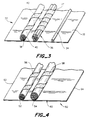
- Figure 3 illustrates a flat multi-component cable assembly 32 comprising carrier (support substrate) film 33 which carries an insulated wire 34 , bundles of wires 36 helically wrapped in overlapping relation by flexible affixment means 37 and a group of insulated wires of various sizes 38 surrounded by a jacket 40 which in turn is wrapped in a flexible affixment means 42 in which consecutive turns are separate from one another.
- Figure 4 illustrates a flat multi-component cable assembly 50 comprising cable bundle 52 , which has flexible affixment means 56 spirally wrapped around it and cable bundle 54 , which has flexible affixment means 58 spirally wrapped around it. In each case consecutive turns of the spiral wraps are spatially separated from one another.
- the cable bundles are secured in substantially parallel relation to one another along the long axis of a support substrate film 60 .
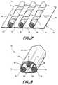
- the flexible affixment means 56 and 58 are secured by melt bonding to the support substrate film 60 , which has a first edge region 62 and a second edge region 64 of a short dimension (transverse to the long axis of the components) extending sufficiently beyond the cable bundles that the edges may be brought around and over the cable bundles as shown in Figure 5 and secured together at 66 to form an edge sealed tubular cover for the cable assembly or sealed together 68 , as shown in Figure 6, to form an overlapped tubular cover.
- the tubular cover is flattened to form first and second interior facing surfaces, the cable components are advantageously attached to the same surface and thus may, if desired be located quite close to one another as is also shown in Figure 6.
- Figure 7 illustrates a flat multi-component cable assembly 70 comprising a first cable bundle 72 , which has flexible affixment means 74 spirally wrapped around it, a second cable bundle 76 , which has flexible affixment means 78 spirally wrapped around it and a third cable bundle 80 , which has flexible affixment means 82 spirally wrapped around it.
- consecutive turns of the spiral wraps are spatially separated form one another.
- the cable bundles are secured in substantially parallel relation to one another.
- the cable bundles are secured in substantially parallel relation to one another along the long axis of a support substrate film 84 by bonding the flexible affixment means 74, 78 and 82 to the carrier film 84 .
- the support substrate film has a first edge region 86 and a second edge region 88 of its short (transverse) dimension extending sufficiently beyond the cable bundles, which are located at a sufficient distance transversely from each other that the support substrate can be folded along its long axis around the first and second cable bundles so that the first and second edge regions may be brought together as shown in Figure 8 and secured together at 87 to form at tubular cover for the cable assembly in which the tubular cover has a first interior surface 90 opposite to a second interior surface 92 .
- the tubular cover is flattened so that it has a first interior surface 90 opposing a second interior surface 92 then the first cable bundle 72 and the second cable bundle 76 are secured through their corresponding flexible affixment means 74 and 78 (illustrated in Figure 8) to the first interior surface 90 of the tubular cover at 75 and 79 and the third cable bundle 80 is secured through it flexible affixment means 82 to the second interior surface 92 of the tubular cover at 83 such that the third cable bundle is positioned between the first and second cable bundles (illustrated in both Figure 8 and Figure 9).
- Figure 10 shows an apparatus for the manufacture of multi-component cable assemblies of the invention.
- the cable components which are to be secured to the backing with affixment means are first wrapped with the affixment means using conventional spiral or other forms of wrapping equipment.
- the cable components 144 include at least one component which has been wrapped with flexible affixment means.
- the support substrate 140 is paid off from a spool 141 wound around roller 142 , where it is heated to a temperature sufficient to obtain the desired bond with a hot air blower 143 . It is then brought in contact with the cable components which are arranged horizontally in a single layer 144 .
- the cable components are also heated by a hot air blower 145 .
- the bonding is achieved between the support substrate and the affixment means and/or cable components by passing the heated support substrate and the cable components between rollers 142 and 146 with and applied pressure of approximately 20 psi.
- the laminated cable assembly is then wound around roller 148 , and through a sent of wire guides 149 and 150 to the caterpillar take up 151 . If desired, excess material on both sides forming first and second end regions may be brought around the bonded cable components, and heat sealed together with an in-line wrapping and sealing unit 152 .
- Figure 10 shows the final stages of wrapping the support substrate around the cable components and then securing the first edge region of the support substrate to the second edge region thereof, it is to be understood that these steps, if desired could be carried out as a separate operation from the steps of providing the cable components, wrapping selected cable components in flexible affixment means, and securing flexible affixment means to support substrate. Separating these later steps of the method of the invention from the above mentioned other steps has the advantage that such other steps may also be used for providing products of the invention secured to support substrate which are not intended to be formed into tubular covers for cable components without having to remove the equipment used informing such covers.
- the conductor may comprise an optical fiber surrounded with a layer of polymeric material (typically the jacket of a fiber optic cable).
- a layer of polymeric material typically the jacket of a fiber optic cable.
- the term conductor is used herein to encompass a variety of possible arrangements of electrical conductors as well as optical fiber cables or individual optical fibers surrounded with a protective polymeric material.
- the term insulated conductor is used herein to refer to any conductor or conductor arrangement surrounded by a layer of polymeric material.
- Polymeric material used as insulation for conductors in the invention may comprise one or more layers independently selected from polymers and copolymers of ethylene such as low density, high density and linear low density polyethylenes, ethylene-vinyl acetate or ethylene-propylene copolymers; polymers and copolymers of vinylidene fluoride such as polyvinylidene fluoride or vinylidene fluoride-hexafluoropropylene copolymers (including terpolymers); polymers and copolymers of tetrafluoroethylene such as poly(tetrafluoro-ethylene) and ethylenetetrafluoroethylene copolymers (including terpolymers)p; siloxanes; ethylenetrichlorofluoroethylene copolymers, polyamides, in particular, aromatic polyamides, polyimides, polyarylene ethers and the like.
- the polymeric material may be crosslinked if desired to provide improved properties, particularly at elevated temperatures.
- Suitable materials for use as affixment means include polymers and copolymers of vinylidene fluoride such as polyvinylidene fluoride or vinylidene fluoride-hexafluoro-propylene copolymers (including terpolymers)p; polymers and copolymers of tetrafluoroethylene such as poly(tetrafluoroethylene) and ethylenetetrafluoroethylene copolymer (including terpolymers); siloxanes; ethylenetrichlorofluoroethylene copolymers, polyamides, in particular, aromatic polyamides, polyimides, polyesters such as polyethylene terephthalate or polybutylene terephthalate, polyarylene ethers and the like.
- vinylidene fluoride such as polyvinylidene fluoride or vinylidene fluoride-hexafluoro-propylene copolymers (including terpolymers)p
- Suitable materials for use as the carrier backing film include polymers and copolymers of vinylidene fluoride such as polyvinylidene fluoride or vinylidene fluoride-hexafluoropropylene copolymers (including terpolymers); polymers and copolymers of tetrafluoroethylene such as poly(tetrafluoroethylene) and ethylenetetrafluoroethylene copolymer (including terpolymers); siloxanes; ethylenetrichlorofluoroethylene copolymers, polyamides, in particular, aromatic polyamides, polyimides, polyesters such as polyethylene terephthalate or polybutylene terephthalate, polyarylene ethers and the like.
- vinylidene fluoride such as polyvinylidene fluoride or vinylidene fluoride-hexafluoropropylene copolymers (including terpolymers)
- tetrafluoroethylene such as poly(tetrafluor
- the cable components may comprise single insulated conductors; coaxial shielded single or multi conductors, foil wrapped, braided or extrusion jacketed; insulated conductor wire bundles comprising from 2 to 100 conductors; bundles of mixed single and multi conductor components and the like.
- the bundles may if desired be extrusion coated with jackets.
- extruded jackets do not function satisfactorily as flexible jacketing means of the invention and as the flexible jacketing means and especially the tubular covers of the invention formed from the carrier films function to provide very good mechanical protection for the cable components, in many circumstances, such extruded jackets are unnecessary.
- the components for the flat cable of this example are 3 sets of cables, each containing 10 Mil-W 81044/12-26 wires twisted together and spiral wrapped with 3 mils thick and 0.25 inch wide Kynarflex® 2800 tape.
- the spacing between the spirals of the wrapped tape is 0.25 inch.
- the bonding substrate is a woven Dacron® polyester fabric, having a weight of 1.25 oz. Per square yard, a denier of 10 and a 72/50 count with 400 micron openings.
- This fabric was impregnated with a Kynarflex® 2800 emulsion producing a total fabric weight of 3.6 oz. Per square yard, and a thickness of 4 mils. The fabric was cut to a width of 4 inches.
- the bonding operation was carried out in equipment similar to that shown in Figure 10, using the following procedure.
- the boated fabric 140 was paid off from a spool 141 and wound around roller 142 , where it was heated to the melting temperature of the impregnant with a hot air blower 143 . It was then brought in contact with the 3 sets of wrapped cables which are arranged horizontally in a single layer 144 . The wrapped cables were also heated by a hot air blower 145 .
- the bonding was achieved between the impregnant in the coated fabric and the wrapping tape by passing the heated fabric and the wrapped cables between rollers 142 and 146 with an applied pressure of approximately 20 psi.
- the laminated cable assembly was then wound around roller 148 , and through a set of wire guides 149 and 150 to the caterpillar take up 151 .
- Excess fabric on both sides formed first and second end regions which were brought around the bonded cables, and heat sealed together with an in-line wrapping and sealing unit 152 .
- Example 1 is repeated using as the wrapping tape and the bonding substrate a 1 mil polyethylene film pre-laminated to a 1 mil polyester film support layer.
- the polyethylene side of the laminated film faced outwards after being spirally wrapped around the cables.
- the bonding operation is carried out using the procedure and equipment as described in Example 1 with the polyethylene layer of the spiral wrap being fused to the polyethylene layer of the bonding substrate.
- Excess bonding substrate on both sides formed first and second end regions which were brought around the bonded cables, and heat sealed together with a hot melt polyester based adhesive in an in-line wrapping and sealing unit.
- the components for the flat cable of this example are 5 sets of primary wires Mil-W-22759/32-22 and 3 sets of multi-conductor cables, each containing 20 Mil-W-22759/32-26 wires twisted together.
- Each set of the multi-conductor cables is spiral wrapped with a 2 mil Tefzel® 280 tape. The spirals are 50 percent overlapped.
- the bonding substrate is a plain weave fiber glass fabric, having a weight of 1.45 oz. per square yard. This glass fabric was impregnated with a Tefzel® 280 emulsion producing a total fabric weight of 2 oz. per square yard, and a thickness of 3 mils.
- the bonding operation is carried out using the procedure and equipment described in Example 1 with the glass fabric being fused to the Tefzel® wrappings of the multi-conductor cables and to the jackets of the primary wires. Excess glass fabric on both sides of the bonded cables is trimmed off by an in-line slitter.
- Example 3 is repeated with the multi-conductor cables and primary wires prearranged in such a way that when the excess glass fabric on both sides of the bonded cables was brought around to be heat sealed in an in-line wrapping and sealing unit thereby forming a tubular cover for the multi-component cable assembly such that some of the multi-conductor cables and primary wires were bonded to the bottom and some to the top of the tubular cover.
- the finished multi-component cable assembly can be reversibly deformed into a tubular configuration enabling the assembly to be bent during installation in tight spaces.
Claims (9)
- Assemblage de câble multicomposant qui peut être coudé ou tortillé et qui comporte(1) un substrat (12) de support ;(2) un composant formant câble qui comprend un conducteur isolé (23, 24, 25) ; et(3) un moyen d'attache (22) qui(a) est enroulé en spirale autour du composant formant câble afin que le composant formant câble puisse glisser par rapport au moyen d'attache, et(b) est fixé au substrat de support.
- Assemblage de câble selon la revendication 1, contenant un premier composant formant câble comprenant un premier conducteur isolé ; un premier moyen d'attache qui (a) est enroulé en spirale autour du premier composant formant câble afin que le premier composant formant câble puisse glisser par rapport au premier moyen d'attache, et (b) est fixé au substrat de support ; un second composant formant câble comprenant un second conducteur isolé ; et un second moyen d'attache qui (a) est enroulé en spirale autour du second composant formant câble afin que le second composant formant câble puisse glisser par rapport au second moyen d'attache, et (b) est fixé au substrat de support.
- Assemblage de câble selon la revendication 2, dans lequel le substrat de support se présente sous la forme d'un film ayant des zones de bords qui sont fixées l'une à l'autre pour former une enveloppe tubulaire qui recouvre les composants formant câbles et les moyens d'attache.
- Assemblage de câble selon la revendication 3, qui peut être aplati afin que, (i) les premier et second composants formant câbles soient alignés, et (ii) l'enveloppe tubulaire comprenne une première surface intérieure principale à laquelle le premier moyen d'attache est fixé, et une seconde surface intérieure principale qui est opposée à la première surface intérieure principale et à laquelle le second moyen d'attache est fixé.
- Assemblage de câble selon la revendication 3, qui peut être aplati afin que (i) les premier et second composants formant câbles soient alignés et (ii) l'enveloppe tubulaire comprenne une première surface intérieure principale à laquelle les premier et second moyens d'attache sont fixés, et une seconde surface intérieure principale qui est opposée à la première surface principale et à laquelle aucun moyen d'attache n'est fixé.
- Assemblage de câble selon l'une quelconque des revendications précédentes, dans lequel le composant formant câble comprend plusieurs conducteurs métalliques, chacun desdits conducteurs étant entouré d'une couche d'isolant polymérique.
- Assemblage de câble selon l'une quelconque des revendications précédentes, dans lequel le moyen d'attache est un film polymérique qui est enroulé autour du composant formant câble afin que des spires consécutives du film se chevauchent.
- Assemblage de câble selon l'une quelconque des revendications 1 à 6, dans lequel le moyen d'attache est un film polymérique qui est enroulé autour du composant formant câble afin que des spires consécutives du film soient espacées les unes des autres.
- Assemblage de câble selon la revendication 7 ou 8, dans lequel le substrat de support comprend une matière polymérique et le film polymérique enroulé est lié par fusion au substrat de support.
Applications Claiming Priority (3)
| Application Number | Priority Date | Filing Date | Title |
|---|---|---|---|
| US08/028,710 US5502287A (en) | 1993-03-10 | 1993-03-10 | Multi-component cable assembly |
| US28710 | 1993-03-10 | ||
| PCT/US1994/001497 WO1994020967A1 (fr) | 1993-03-10 | 1994-02-14 | Ensemble multicomposants pour cables |
Publications (2)
| Publication Number | Publication Date |
|---|---|
| EP0688461A1 EP0688461A1 (fr) | 1995-12-27 |
| EP0688461B1 true EP0688461B1 (fr) | 1998-05-27 |
Family
ID=21844991
Family Applications (1)
| Application Number | Title | Priority Date | Filing Date |
|---|---|---|---|
| EP94909595A Expired - Lifetime EP0688461B1 (fr) | 1993-03-10 | 1994-02-14 | Ensemble multicomposants pour cables |
Country Status (8)
| Country | Link |
|---|---|
| US (1) | US5502287A (fr) |
| EP (1) | EP0688461B1 (fr) |
| JP (1) | JPH08507641A (fr) |
| AT (1) | ATE166743T1 (fr) |
| CA (1) | CA2157924C (fr) |
| DE (1) | DE69410601T2 (fr) |
| HK (1) | HK1011515A1 (fr) |
| WO (1) | WO1994020967A1 (fr) |
Families Citing this family (29)
| Publication number | Priority date | Publication date | Assignee | Title |
|---|---|---|---|---|
| SE502953C2 (sv) * | 1992-11-09 | 1996-02-26 | Atlas Copco Tools Ab | Flerpartskabel med flexibel zon |
| FR2742258B1 (fr) * | 1995-12-08 | 1998-02-27 | Axoncable Sa | Cable plat a faible marge |
| US6841735B1 (en) * | 1996-04-03 | 2005-01-11 | Methode Electronics, Inc. | Flat cable and modular rotary anvil to make same |
| US5784258A (en) * | 1997-04-11 | 1998-07-21 | Xerox Corporation | Wiring board for supporting an array of imaging chips |
| DE10060070C2 (de) * | 2000-12-01 | 2003-04-30 | Webasto Vehicle Sys Int Gmbh | Kabelbaumanordnung, insbesondere für Fahrzeuge |
| DE60116286D1 (de) * | 2001-07-26 | 2006-02-02 | Draka Comteq Bv | Optisches Faserbändchen |
| WO2004024429A1 (fr) * | 2002-09-11 | 2004-03-25 | Fisher & Paykel Healthcare Limited | Conduits et procede de fabrication |
| US20040188130A1 (en) * | 2003-03-28 | 2004-09-30 | Humberto Herrera | Method and apparatus for dressing substantially parallel cables |
| JP4851180B2 (ja) * | 2005-12-19 | 2012-01-11 | 矢崎総業株式会社 | ワイヤハーネス及びワイヤハーネスの扁平形状製造方法 |
| WO2008137671A1 (fr) * | 2007-05-02 | 2008-11-13 | Mag Industrial Automation Systems, Llc | Procédé pour fabriquer un panneau de soubassement composite |
| GB0823407D0 (en) * | 2008-12-23 | 2009-01-28 | Nexan Technologies Ltd | Apparatus for storing data |
| GB2467404B (en) | 2008-12-23 | 2011-12-14 | Nexsan Technologies Ltd | Electronic apparatus |
| EP2209126A3 (fr) * | 2009-01-19 | 2012-04-04 | Dräger Medical GmbH | Câble déformable flexible doté d'un composite textile pour des applications électromédicales |
| US20110001314A1 (en) * | 2009-07-01 | 2011-01-06 | Xerox Corporation | Security codes within scratch-off layers and method of embedding thereof |
| US20110253408A1 (en) * | 2010-04-16 | 2011-10-20 | Rockbestos Surprenant Cable Corp. | Method and System for a Down-hole Cable having a Liquid Bonding Material |
| JP5704127B2 (ja) * | 2012-06-19 | 2015-04-22 | 日立金属株式会社 | 多対差動信号伝送用ケーブル |
| US9411120B2 (en) * | 2013-03-15 | 2016-08-09 | Commscope, Inc. Of North Carolina | Multi-cable breakout assembly |
| CA2909990C (fr) | 2013-04-24 | 2021-02-09 | Wireco Worldgroup Inc. | Cable electromecanique haute puissance a faible resistance |
| US10373741B2 (en) * | 2017-05-10 | 2019-08-06 | Creganna Unlimited Company | Electrical cable |
| US10964448B1 (en) * | 2017-12-06 | 2021-03-30 | Amphenol Corporation | High density ribbon cable |
| JP6939704B2 (ja) * | 2018-05-25 | 2021-09-22 | 株式会社オートネットワーク技術研究所 | 配線部材 |
| US10398873B1 (en) * | 2018-07-20 | 2019-09-03 | Automated Assembly Corporation | Rolled substrate cable |
| JP7192628B2 (ja) * | 2018-08-22 | 2022-12-20 | 株式会社オートネットワーク技術研究所 | 配線部材 |
| JP7188244B2 (ja) * | 2019-04-05 | 2022-12-13 | 株式会社オートネットワーク技術研究所 | 配線部材 |
| JP7211331B2 (ja) * | 2019-10-23 | 2023-01-24 | 株式会社オートネットワーク技術研究所 | 配線部材 |
| JP7294082B2 (ja) * | 2019-11-20 | 2023-06-20 | 住友電装株式会社 | 配線部材 |
| JP2021163568A (ja) * | 2020-03-31 | 2021-10-11 | 住友電装株式会社 | 配線部材 |
| JP2023006176A (ja) * | 2021-06-30 | 2023-01-18 | 株式会社オートネットワーク技術研究所 | 配線部材 |
| CN113782272B (zh) * | 2021-09-29 | 2023-01-24 | 安徽顺信线缆有限公司 | 一种新能源汽车用散热型电缆 |
Citations (7)
| Publication number | Priority date | Publication date | Assignee | Title |
|---|---|---|---|---|
| US3745230A (en) * | 1972-01-12 | 1973-07-10 | W Kelly | Metal sheathed electrical wire cable |
| US3819848A (en) * | 1972-09-07 | 1974-06-25 | Rists Wires & Cables Ltd | Wiring harnesses |
| US4012577A (en) * | 1975-04-30 | 1977-03-15 | Spectra-Strip Corporation | Multiple twisted pair multi-conductor laminated cable |
| US4093480A (en) * | 1974-10-11 | 1978-06-06 | Amp Incorporated | Method for making electrical connectors |
| US4974798A (en) * | 1989-12-18 | 1990-12-04 | Chrysler Corporation | Vehicle wiring harness cable mounting assembly structure |
| US5030794A (en) * | 1990-02-14 | 1991-07-09 | Rlp Tool Co. | Accessory RF shields for multiple-line ribbon cables |
| US5111002A (en) * | 1991-01-28 | 1992-05-05 | Omega Engineering, Inc. | Method of fabricating thermocouple cable and the cable resulting therefrom |
Family Cites Families (40)
| Publication number | Priority date | Publication date | Assignee | Title |
|---|---|---|---|---|
| AT254964B (de) * | 1963-09-13 | 1967-06-12 | Auto Union Gmbh | Verfahren zur Ummantelung gebündelter Leitungen |
| US3653121A (en) * | 1969-01-27 | 1972-04-04 | Hitachi Ltd | Method for manufacturing a memory plane |
| FR2036798A1 (en) * | 1969-04-02 | 1970-12-31 | Fileca | Flat multi-conductor insulated cable |
| US3613230A (en) * | 1969-04-29 | 1971-10-19 | Bunker Ramo | Method of fabricating coaxial circuitry |
| GB1342716A (en) * | 1970-07-11 | 1974-01-03 | Rists Wires & Cables Ltd | Wiring harnesses |
| FR2185839B1 (fr) * | 1972-05-25 | 1976-10-29 | Labinal | |
| US4000348A (en) * | 1974-10-15 | 1976-12-28 | Carlisle Corporation | Flat multiconductor cable and process for manufacture thereof |
| GB1534014A (en) * | 1975-10-16 | 1978-11-29 | Xerox Corp | Electrical cable and coupling arrangement |
| US4183010A (en) * | 1975-12-08 | 1980-01-08 | Gte Sylvania Incorporated | Pressure compensating coaxial line hydrophone and method |
| IT1067545B (it) * | 1976-08-30 | 1985-03-16 | Pirelli | Cavi a isolante estruso con schermo concentrico pzerfezionato |
| US4165559A (en) * | 1976-10-28 | 1979-08-28 | Eltra Corporation | Re-formable multi-conductor flat cable |
| US4113335A (en) * | 1976-10-28 | 1978-09-12 | Eltra Corporation | Re-formable multi-conductor flat cable |
| US4138193A (en) * | 1977-09-27 | 1979-02-06 | General Cable Corporation | Multiple fiber laminate for optical waveguides |
| US4616717A (en) * | 1978-11-09 | 1986-10-14 | Tel Tec Inc. | Flexible wire cable and process of making same |
| FR2457548A1 (fr) * | 1979-05-23 | 1980-12-19 | Cables De Lyon Geoffroy Delore | Procede de fabrication de cables electriques a conducteurs multiples, et dispositif de mise en oeuvre du procede |
| US4287385A (en) * | 1979-09-12 | 1981-09-01 | Carlisle Corporation | Shielded flat cable |
| FR2516294A1 (fr) * | 1981-11-06 | 1983-05-13 | Esswein Sa | Procede de realisation d'une bande de fils electriques, moyens de mise en oeuvre et bande resultant de ce procede |
| US4478778A (en) * | 1981-12-18 | 1984-10-23 | Amp Incorporated | Method of manufacturing flat peelable cable |
| US4501929A (en) * | 1982-05-06 | 1985-02-26 | The United States Of America As Represented By The Secretary Of The Air Force | Multiconductor flat cable |
| US4548661A (en) * | 1982-05-06 | 1985-10-22 | The United States Of America As Represented By The Secretary Of The Air Force | Method for assembling a multiconductor flat cable |
| US4468089A (en) * | 1982-07-09 | 1984-08-28 | Gk Technologies, Inc. | Flat cable of assembled modules and method of manufacture |
| US4678709A (en) * | 1982-09-15 | 1987-07-07 | Raychem Corporation | Electrical insulation |
| US4486619A (en) * | 1983-05-12 | 1984-12-04 | Minnesota Mining And Manufacturing Company | Uniform twisted wire pair electrical ribbon cable |
| US4538024A (en) * | 1983-07-01 | 1985-08-27 | Amp Incorporated | Flat multiconductor cable extruded on a wheel |
| JPS60169904U (ja) * | 1984-04-20 | 1985-11-11 | 株式会社 潤工社 | ストリップラインケーブル |
| US4625074A (en) * | 1985-03-05 | 1986-11-25 | Cooper Industries, Inc. | Mass terminable flat cable |
| US4626298A (en) * | 1985-03-25 | 1986-12-02 | Trw Inc. | Method of making flat multiple conductor cable |
| US4678864A (en) * | 1985-06-27 | 1987-07-07 | Cooper Industries, Inc. | Mass terminable flat cable assembly with readily separable ground plane |
| US4767891A (en) * | 1985-11-18 | 1988-08-30 | Cooper Industries, Inc. | Mass terminable flat cable and cable assembly incorporating the cable |
| US4715677A (en) * | 1985-12-24 | 1987-12-29 | Sumitomo Electric Research Triangle, Inc. | Ruggedized optical fiber cable |
| US4800236A (en) * | 1986-08-04 | 1989-01-24 | E. I. Du Pont De Nemours And Company | Cable having a corrugated septum |
| US4783578A (en) * | 1986-08-22 | 1988-11-08 | Flexwatt Corporation | Multi-conductor cables |
| US4711811A (en) * | 1986-10-22 | 1987-12-08 | E. I. Du Pont De Nemours And Company | Thin wall cover on foamed insulation on wire |
| US4900126A (en) * | 1988-06-30 | 1990-02-13 | American Telephone & Telegraph Co. | Bonded array of transmission media |
| JP2900342B2 (ja) * | 1988-12-27 | 1999-06-02 | 矢崎総業株式会社 | フラットワイヤハーネスの製造方法および装置 |
| US4926007A (en) * | 1989-03-03 | 1990-05-15 | W. H. Brady Co. | Shielded flexible connector and process therefor |
| US5111102A (en) * | 1989-05-25 | 1992-05-05 | Meeks Crawford R | Magnetic bearing structure |
| US5278356A (en) * | 1990-06-08 | 1994-01-11 | Miller Terry Q | Hold-down tape for electrical cables |
| JPH04302810A (ja) * | 1991-03-29 | 1992-10-26 | Victor Co Of Japan Ltd | 薄膜磁気ヘッド |
| US5268531A (en) * | 1992-03-06 | 1993-12-07 | Raychem Corporation | Flat cable |
-
1993
- 1993-03-10 US US08/028,710 patent/US5502287A/en not_active Expired - Lifetime
-
1994
- 1994-02-14 WO PCT/US1994/001497 patent/WO1994020967A1/fr active IP Right Grant
- 1994-02-14 AT AT94909595T patent/ATE166743T1/de not_active IP Right Cessation
- 1994-02-14 DE DE69410601T patent/DE69410601T2/de not_active Expired - Fee Related
- 1994-02-14 CA CA002157924A patent/CA2157924C/fr not_active Expired - Fee Related
- 1994-02-14 JP JP6519988A patent/JPH08507641A/ja not_active Ceased
- 1994-02-14 EP EP94909595A patent/EP0688461B1/fr not_active Expired - Lifetime
-
1998
- 1998-11-25 HK HK98112320A patent/HK1011515A1/xx not_active IP Right Cessation
Patent Citations (7)
| Publication number | Priority date | Publication date | Assignee | Title |
|---|---|---|---|---|
| US3745230A (en) * | 1972-01-12 | 1973-07-10 | W Kelly | Metal sheathed electrical wire cable |
| US3819848A (en) * | 1972-09-07 | 1974-06-25 | Rists Wires & Cables Ltd | Wiring harnesses |
| US4093480A (en) * | 1974-10-11 | 1978-06-06 | Amp Incorporated | Method for making electrical connectors |
| US4012577A (en) * | 1975-04-30 | 1977-03-15 | Spectra-Strip Corporation | Multiple twisted pair multi-conductor laminated cable |
| US4974798A (en) * | 1989-12-18 | 1990-12-04 | Chrysler Corporation | Vehicle wiring harness cable mounting assembly structure |
| US5030794A (en) * | 1990-02-14 | 1991-07-09 | Rlp Tool Co. | Accessory RF shields for multiple-line ribbon cables |
| US5111002A (en) * | 1991-01-28 | 1992-05-05 | Omega Engineering, Inc. | Method of fabricating thermocouple cable and the cable resulting therefrom |
Also Published As
| Publication number | Publication date |
|---|---|
| CA2157924A1 (fr) | 1994-09-15 |
| HK1011515A1 (en) | 1999-07-09 |
| WO1994020967A1 (fr) | 1994-09-15 |
| CA2157924C (fr) | 2003-08-05 |
| DE69410601T2 (de) | 1999-02-25 |
| US5502287A (en) | 1996-03-26 |
| ATE166743T1 (de) | 1998-06-15 |
| EP0688461A1 (fr) | 1995-12-27 |
| DE69410601D1 (de) | 1998-07-02 |
| JPH08507641A (ja) | 1996-08-13 |
Similar Documents
| Publication | Publication Date | Title |
|---|---|---|
| EP0688461B1 (fr) | Ensemble multicomposants pour cables | |
| US3757029A (en) | Shielded flat cable | |
| CA1202094A (fr) | Cable en nappe modulaire, et sa fabrication | |
| US5268531A (en) | Flat cable | |
| US5274196A (en) | Fiberglass cloth resin tape insulation | |
| CA1157073A (fr) | Element chauffant electrique pouvant servir de couverture thermoretrecissable, et methode de fabrication | |
| US4045611A (en) | Hermetic lead wire | |
| CA2132980C (fr) | Cable plat | |
| FI85779B (fi) | Signaltransmissionskabel. | |
| US7247797B2 (en) | Communication cable | |
| MXPA01012584A (es) | Cable de datos de alto desempeno. | |
| US9928943B1 (en) | Communication cables incorporating separator structures | |
| US3509269A (en) | Thermal barriers for cables | |
| KR100671184B1 (ko) | 고성능 데이터 케이블 및 ul 910 플리넘 비불소화자켓의 고성능 데이터 케이블 | |
| US4851060A (en) | Multilayer wrapped insulated magnet wire | |
| US4761520A (en) | Spiral wrapped insulated magnet wire | |
| JPH10511502A (ja) | 難燃性フラットケーブル製造の装置および方法 | |
| US4241121A (en) | Combined shield and core wrap for telecommunication cables and the like | |
| CA1318949C (fr) | Materiaux isolants partiellements ou entierement faits de film polyester | |
| EP0222291A2 (fr) | Ruban composite pour l'isolation de câbles électriques et câble électrique utilisant ledit ruban dans son isolation | |
| US10276281B1 (en) | Communication cables with twisted tape separators | |
| US3614299A (en) | Low thermal conductivity cable core wrap | |
| US5106686A (en) | Multilayer wrapped insulated magnet wire | |
| KR820002058B1 (ko) | 열수축성 커버(熱收縮性 cover) | |
| JPH0129691Y2 (fr) |
Legal Events
| Date | Code | Title | Description |
|---|---|---|---|
| PUAI | Public reference made under article 153(3) epc to a published international application that has entered the european phase |
Free format text: ORIGINAL CODE: 0009012 |
|
| 17P | Request for examination filed |
Effective date: 19950909 |
|
| AK | Designated contracting states |
Kind code of ref document: A1 Designated state(s): AT BE CH DE DK ES FR GB GR IE IT LI NL PT SE |
|
| 17Q | First examination report despatched |
Effective date: 19960415 |
|
| GRAG | Despatch of communication of intention to grant |
Free format text: ORIGINAL CODE: EPIDOS AGRA |
|
| GRAG | Despatch of communication of intention to grant |
Free format text: ORIGINAL CODE: EPIDOS AGRA |
|
| GRAH | Despatch of communication of intention to grant a patent |
Free format text: ORIGINAL CODE: EPIDOS IGRA |
|
| GRAH | Despatch of communication of intention to grant a patent |
Free format text: ORIGINAL CODE: EPIDOS IGRA |
|
| GRAA | (expected) grant |
Free format text: ORIGINAL CODE: 0009210 |
|
| AK | Designated contracting states |
Kind code of ref document: B1 Designated state(s): AT BE CH DE DK ES FR GB GR IE IT LI NL PT SE |
|
| PG25 | Lapsed in a contracting state [announced via postgrant information from national office to epo] |
Ref country code: NL Free format text: LAPSE BECAUSE OF FAILURE TO SUBMIT A TRANSLATION OF THE DESCRIPTION OR TO PAY THE FEE WITHIN THE PRESCRIBED TIME-LIMIT Effective date: 19980527 Ref country code: LI Free format text: LAPSE BECAUSE OF FAILURE TO SUBMIT A TRANSLATION OF THE DESCRIPTION OR TO PAY THE FEE WITHIN THE PRESCRIBED TIME-LIMIT Effective date: 19980527 Ref country code: IT Free format text: LAPSE BECAUSE OF FAILURE TO SUBMIT A TRANSLATION OF THE DESCRIPTION OR TO PAY THE FEE WITHIN THE PRESCRIBED TIME-LIMIT;WARNING: LAPSES OF ITALIAN PATENTS WITH EFFECTIVE DATE BEFORE 2007 MAY HAVE OCCURRED AT ANY TIME BEFORE 2007. THE CORRECT EFFECTIVE DATE MAY BE DIFFERENT FROM THE ONE RECORDED. Effective date: 19980527 Ref country code: GR Free format text: LAPSE BECAUSE OF NON-PAYMENT OF DUE FEES Effective date: 19980527 Ref country code: ES Free format text: THE PATENT HAS BEEN ANNULLED BY A DECISION OF A NATIONAL AUTHORITY Effective date: 19980527 Ref country code: CH Free format text: LAPSE BECAUSE OF FAILURE TO SUBMIT A TRANSLATION OF THE DESCRIPTION OR TO PAY THE FEE WITHIN THE PRESCRIBED TIME-LIMIT Effective date: 19980527 Ref country code: BE Free format text: LAPSE BECAUSE OF FAILURE TO SUBMIT A TRANSLATION OF THE DESCRIPTION OR TO PAY THE FEE WITHIN THE PRESCRIBED TIME-LIMIT Effective date: 19980527 Ref country code: AT Free format text: LAPSE BECAUSE OF FAILURE TO SUBMIT A TRANSLATION OF THE DESCRIPTION OR TO PAY THE FEE WITHIN THE PRESCRIBED TIME-LIMIT Effective date: 19980527 |
|
| REF | Corresponds to: |
Ref document number: 166743 Country of ref document: AT Date of ref document: 19980615 Kind code of ref document: T |
|
| REG | Reference to a national code |
Ref country code: CH Ref legal event code: EP |
|
| REF | Corresponds to: |
Ref document number: 69410601 Country of ref document: DE Date of ref document: 19980702 |
|
| ET | Fr: translation filed | ||
| REG | Reference to a national code |
Ref country code: IE Ref legal event code: FG4D |
|
| PG25 | Lapsed in a contracting state [announced via postgrant information from national office to epo] |
Ref country code: SE Free format text: LAPSE BECAUSE OF FAILURE TO SUBMIT A TRANSLATION OF THE DESCRIPTION OR TO PAY THE FEE WITHIN THE PRESCRIBED TIME-LIMIT Effective date: 19980827 Ref country code: PT Free format text: LAPSE BECAUSE OF FAILURE TO SUBMIT A TRANSLATION OF THE DESCRIPTION OR TO PAY THE FEE WITHIN THE PRESCRIBED TIME-LIMIT Effective date: 19980827 Ref country code: DK Free format text: LAPSE BECAUSE OF FAILURE TO SUBMIT A TRANSLATION OF THE DESCRIPTION OR TO PAY THE FEE WITHIN THE PRESCRIBED TIME-LIMIT Effective date: 19980827 |
|
| NLV1 | Nl: lapsed or annulled due to failure to fulfill the requirements of art. 29p and 29m of the patents act | ||
| REG | Reference to a national code |
Ref country code: CH Ref legal event code: PL |
|
| PG25 | Lapsed in a contracting state [announced via postgrant information from national office to epo] |
Ref country code: IE Free format text: LAPSE BECAUSE OF NON-PAYMENT OF DUE FEES Effective date: 19990214 |
|
| PLBE | No opposition filed within time limit |
Free format text: ORIGINAL CODE: 0009261 |
|
| STAA | Information on the status of an ep patent application or granted ep patent |
Free format text: STATUS: NO OPPOSITION FILED WITHIN TIME LIMIT |
|
| 26N | No opposition filed | ||
| REG | Reference to a national code |
Ref country code: IE Ref legal event code: MM4A |
|
| REG | Reference to a national code |
Ref country code: GB Ref legal event code: IF02 |
|
| PGFP | Annual fee paid to national office [announced via postgrant information from national office to epo] |
Ref country code: GB Payment date: 20080227 Year of fee payment: 15 |
|
| PGFP | Annual fee paid to national office [announced via postgrant information from national office to epo] |
Ref country code: DE Payment date: 20080331 Year of fee payment: 15 |
|
| GBPC | Gb: european patent ceased through non-payment of renewal fee |
Effective date: 20090214 |
|
| PGFP | Annual fee paid to national office [announced via postgrant information from national office to epo] |
Ref country code: FR Payment date: 20090217 Year of fee payment: 16 |
|
| PG25 | Lapsed in a contracting state [announced via postgrant information from national office to epo] |
Ref country code: DE Free format text: LAPSE BECAUSE OF NON-PAYMENT OF DUE FEES Effective date: 20090901 |
|
| PG25 | Lapsed in a contracting state [announced via postgrant information from national office to epo] |
Ref country code: GB Free format text: LAPSE BECAUSE OF NON-PAYMENT OF DUE FEES Effective date: 20090214 |
|
| REG | Reference to a national code |
Ref country code: FR Ref legal event code: ST Effective date: 20101029 |
|
| PG25 | Lapsed in a contracting state [announced via postgrant information from national office to epo] |
Ref country code: FR Free format text: LAPSE BECAUSE OF NON-PAYMENT OF DUE FEES Effective date: 20100301 |