EP0687815A2 - Spiralverdrängermaschine - Google Patents
Spiralverdrängermaschine Download PDFInfo
- Publication number
- EP0687815A2 EP0687815A2 EP95401383A EP95401383A EP0687815A2 EP 0687815 A2 EP0687815 A2 EP 0687815A2 EP 95401383 A EP95401383 A EP 95401383A EP 95401383 A EP95401383 A EP 95401383A EP 0687815 A2 EP0687815 A2 EP 0687815A2
- Authority
- EP
- European Patent Office
- Prior art keywords
- scroll
- circling
- boss
- tooth
- teeth
- Prior art date
- Legal status (The legal status is an assumption and is not a legal conclusion. Google has not performed a legal analysis and makes no representation as to the accuracy of the status listed.)
- Granted
Links
- 239000012530 fluid Substances 0.000 title claims abstract description 45
- 230000006835 compression Effects 0.000 claims description 34
- 238000007906 compression Methods 0.000 claims description 34
- 238000007789 sealing Methods 0.000 claims description 11
- 230000002265 prevention Effects 0.000 claims description 7
- 238000010276 construction Methods 0.000 abstract description 18
- 238000004519 manufacturing process Methods 0.000 abstract description 2
- 238000004904 shortening Methods 0.000 abstract 1
- 238000010586 diagram Methods 0.000 description 7
- 230000010349 pulsation Effects 0.000 description 3
- 239000002131 composite material Substances 0.000 description 2
- 238000003754 machining Methods 0.000 description 2
- 238000000034 method Methods 0.000 description 2
- 238000007796 conventional method Methods 0.000 description 1
- 230000007423 decrease Effects 0.000 description 1
- 230000007547 defect Effects 0.000 description 1
- 230000000593 degrading effect Effects 0.000 description 1
- 230000000694 effects Effects 0.000 description 1
- 230000002093 peripheral effect Effects 0.000 description 1
- 230000035939 shock Effects 0.000 description 1
Images


Classifications
-
- F—MECHANICAL ENGINEERING; LIGHTING; HEATING; WEAPONS; BLASTING
- F04—POSITIVE - DISPLACEMENT MACHINES FOR LIQUIDS; PUMPS FOR LIQUIDS OR ELASTIC FLUIDS
- F04C—ROTARY-PISTON, OR OSCILLATING-PISTON, POSITIVE-DISPLACEMENT MACHINES FOR LIQUIDS; ROTARY-PISTON, OR OSCILLATING-PISTON, POSITIVE-DISPLACEMENT PUMPS
- F04C23/00—Combinations of two or more pumps, each being of rotary-piston or oscillating-piston type, specially adapted for elastic fluids; Pumping installations specially adapted for elastic fluids; Multi-stage pumps specially adapted for elastic fluids
- F04C23/001—Combinations of two or more pumps, each being of rotary-piston or oscillating-piston type, specially adapted for elastic fluids; Pumping installations specially adapted for elastic fluids; Multi-stage pumps specially adapted for elastic fluids of similar working principle
-
- F—MECHANICAL ENGINEERING; LIGHTING; HEATING; WEAPONS; BLASTING
- F04—POSITIVE - DISPLACEMENT MACHINES FOR LIQUIDS; PUMPS FOR LIQUIDS OR ELASTIC FLUIDS
- F04C—ROTARY-PISTON, OR OSCILLATING-PISTON, POSITIVE-DISPLACEMENT MACHINES FOR LIQUIDS; ROTARY-PISTON, OR OSCILLATING-PISTON, POSITIVE-DISPLACEMENT PUMPS
- F04C18/00—Rotary-piston pumps specially adapted for elastic fluids
- F04C18/02—Rotary-piston pumps specially adapted for elastic fluids of arcuate-engagement type, i.e. with circular translatory movement of co-operating members, each member having the same number of teeth or tooth-equivalents
- F04C18/0207—Rotary-piston pumps specially adapted for elastic fluids of arcuate-engagement type, i.e. with circular translatory movement of co-operating members, each member having the same number of teeth or tooth-equivalents both members having co-operating elements in spiral form
- F04C18/0215—Rotary-piston pumps specially adapted for elastic fluids of arcuate-engagement type, i.e. with circular translatory movement of co-operating members, each member having the same number of teeth or tooth-equivalents both members having co-operating elements in spiral form where only one member is moving
- F04C18/0223—Rotary-piston pumps specially adapted for elastic fluids of arcuate-engagement type, i.e. with circular translatory movement of co-operating members, each member having the same number of teeth or tooth-equivalents both members having co-operating elements in spiral form where only one member is moving with symmetrical double wraps
-
- F—MECHANICAL ENGINEERING; LIGHTING; HEATING; WEAPONS; BLASTING
- F04—POSITIVE - DISPLACEMENT MACHINES FOR LIQUIDS; PUMPS FOR LIQUIDS OR ELASTIC FLUIDS
- F04C—ROTARY-PISTON, OR OSCILLATING-PISTON, POSITIVE-DISPLACEMENT MACHINES FOR LIQUIDS; ROTARY-PISTON, OR OSCILLATING-PISTON, POSITIVE-DISPLACEMENT PUMPS
- F04C18/00—Rotary-piston pumps specially adapted for elastic fluids
- F04C18/02—Rotary-piston pumps specially adapted for elastic fluids of arcuate-engagement type, i.e. with circular translatory movement of co-operating members, each member having the same number of teeth or tooth-equivalents
- F04C18/0207—Rotary-piston pumps specially adapted for elastic fluids of arcuate-engagement type, i.e. with circular translatory movement of co-operating members, each member having the same number of teeth or tooth-equivalents both members having co-operating elements in spiral form
- F04C18/0246—Details concerning the involute wraps or their base, e.g. geometry
- F04C18/0253—Details concerning the base
Definitions
- the present invention relates to a scroll type fluid machine.
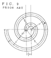
- a conventional scroll type fluid machine generally includes a pair of scroll members of the same shape with a certain thickness, which have clockwise- or counter-clockwise-wound scroll teeth engaged 180 degrees out of phase with each other, with one scroll member fixed and the other performing a circling, but not rotating, motion with respect to the fixed member.
- a fluid is drawn in between the pair of scroll teeth and its volume is progressively reduced and compressed toward the center of a space formed by the paired scroll teeth.
- the scroll tooth is considered as consisting of a plurality of continuous semicircles.
- bearings that support the scroll members are generally provided outside a scroll disk, and a pin crank mechanism to ensure the circular motion is normally mounted on an outer peripheral portion of the disk.
- the conventional scroll type fluid machine has the following problems.
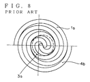
- the scroll teeth are formed in such a way as to allow the fluid compression up to the central portion of the scroll teeth, when we look at the machine as a compressor, it has a relatively large delivery opening at the center for the delivery pressure of 7 kgf/cm2. So, the compressed space mostly comes to communicate with the delivery opening before the compression reaches the central portion. That is, the mechanism of the central portion is not utilized effectively.
- Denoted 3a in Figure 8 is the delivery opening.
- the bearings supporting the rotation and circling motion are located outside the circling scroll disk in the direction of drive shaft end. This means that the circling scroll disk is supported by the bearing on one side only, degrading the precision of the circling motion. This makes it impossible to elongate the scroll tooth length.
- Another drawback is that the bearing cannot be mounted at the position where it can efficiently receive a radial load acting on the scroll tooth that is performing the compression stroke. Because the bearing is installed outside the scroll disk, the bearing is applied a moment, which is a product of the radial load acting on the scroll tooth and the distance to the bearing mounting position. So, the bearing must have an excessively large load withstand strength considering the moment. This bearing position also poses a problem of requiring additional space in the direction of axis.
- a pin crank is commonly employed in recent years.
- the pin crank is usually mounted on the outer periphery of the scroll disk. Because of its mounted position, the pin crank is not free from instability caused by expansion of the circling scroll disk and the accumulated mounting dimension errors of bearing, disk and housing.
- One of the steps taken to solve these problems is to install a shock absorbing structure in the pin crank bearing. This structure, however, causes the circling scroll to vibrate during the circling motion.
- the circling scroll has a boss at the central portion that receives bearings and shafts and the fixed scroll has the central portion of its tooth formed different from that of the circling scroll to allow continuous seal of a compression chamber formed between the engaged circling and fixed scroll teeth during the circling motion.
- a scroll type fluid machine comprising: a circling scroll including a circling disk and a circling scroll tooth provided on the disk, with a boss at a central portion of the circling scroll tooth, the boss being formed of a semicircle on a first side and a semicircle on a second side opposite to the first side, the semicircle on the second side having a radius equal to a radius of the semicircle on the first side plus one half of a thickness of the circling scroll tooth, the geometry of the circling scroll tooth being defined by semicircles spirally connected in series from the boss at the central portion towards an outer periphery, with succeeding semicircles having progressively increasing radii; and a fixed scroll including a fixed disk and a fixed scroll tooth on the disk, with no such a boss as is provided to the circling scroll tooth formed at a central portion thereof, the fixed scroll tooth having an internal end configured such that an internal surface thereof and an external surface of the central portion
- the circling scroll boss receives a crank-shaped eccentric drive shaft (5), off-centered from the drive shaft, and a bearing, and the end of the boss is closed with a wall.
- the end of the boss receives a bearing and a pin crank, which is off-centered from the axis of the crank-shaped drive shaft by the same eccentricity as the eccentric drive shaft (5).
- This construction constitutes a major means to prevent the rotation of the circling scroll itself.
- the other end of the pin crank is supported by a bearing in the frame to allow stable circling motion of the scroll.
- the side of the circling scroll is fitted with a pin-crank-shaped eccentric shaft (15) to prevent the rotation of the circling scroll during the circling motion.
- the eccentric shaft (15) is supported at the other end by a bearing cover through a bearing.
- the left and right scroll teeth are formed in different shapes, with the boss provided at the center of the circling scroll.
- the size of the delivery opening for a required compression ratio is almost the same as that of the conventional scroll teeth of Figure 8, and thus poses no practical problem.
- this invention provides a unique sealing structure of the fixed scroll, which is detailed in the description of embodiments. Because the eccentric shaft from the drive shaft is fitted, together with the bearing, into the boss of the circling scroll, the radial load acting on the scroll tooth is directly borne by the boss efficiently, which allows the drive shaft to be formed short.
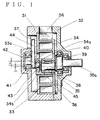
- the left end of the boss is mounted with a pin crank, which is off-centered from the eccentric shaft by a dimension S, as shown in Figure 1.
- the pin crank is supported by a bearing in the frame and performs a function of pivot for the circling motion.
- the provision of the pin crank at this position means that the pin crank is not affected by the thermal expansion in the radial direction during operation and that the circling scroll is supported on both sides at the central portion.
- This construction eliminates the biggest drawback of the conventional scroll that the scroll tooth width cannot be increased because of its cantilever or one-side support structure, and allows the scroll tooth width to be increased to a sufficient size, making it possible to upgrade the delivery capacity of the scroll fluid machine by two or three times.
- an eccentric shaft with the same amount of eccentricity as the pin crank is attached to the side of the circling scroll to support it at two or more points by the pin crank and this eccentric shaft and thereby prevent the rotation and unstable vibration of the circling scroll.
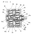
- FIG. 2 shows a two-stage configuration in which the blocks are connected in series.
- the circling scroll has a mirror disk installed at the center, on both sides of which are mounted left and right circling scroll teeth in a so-called twin-type configuration, with the left and right teeth set 180 degrees out of phase with each other.
- the left and right teeth assumes the same positions if they are turned 180 degrees about the drive shaft axis.
- a balance type scroll fluid machine comprising: a central mirror disk of a circling scroll having scroll teeth on both sides, the scroll teeth having the same configuration each with a boss at a central portion thereof and being positioned 180 degrees out of phase about a drive shaft axis to achieve a weight balance therebetween; and fixed scrolls on both sides of the mirror disk, having scroll teeth respectively engaged with corresponding scroll teeth on the mirror disk, one of the scroll teeth of the fixed scrolls having a central arc directed upwardly relative to a center point thereof (G2) which is downwardly off-centered from the drive shaft axis by the same eccentricity as an eccentric drive shaft of the mirror disk, the other of the scroll teeth of the fixed scrolls having a central arc directed downwardly relative to the point (G2), whereby scroll laps on both sides of the mirror disk alternately perform compression operations by 180 degrees.
- the circling scroll mirror disk is mounted with a plurality of pin cranks having a bearing at two or more positions along the outer periphery of the mirror disk to prevent the rotation of the circling scroll during the circling motion.
- the fixed scrolls that engage with the left and right circling scroll teeth are also arranged 180 degrees out of phase with each other. That is, when the left fixed scroll just completes the suction stroke, the right fixed scroll enters the compression stroke, which is 180 degrees apart from the suction stroke.
- the left and right circling scrolls are mounted on both sides of the center mirror disk with the right circling scroll located at a position rotated 180 degrees from the left circling scroll, the halves of the circling scroll divided by a line passing through the drive shaft axis G, as shown in Figure 13, perfectly balance each other in weight. It is noted, however, that the weight correction associated with the bearing 59 must be done by forming drill holes in the boss.
- the circling scroll can be formed to be perfectly balanced, there is no need to install a balance weight. Further, in this configuration if the amount of eccentricity is increased, only the mirror disk needs to be enlarged and the halves of the scroll remains balanced in terms of weight, so that the delivery capacity can easily be increased by increasing the eccentricity without a fear of increasing vibrations. Further, because the compression is performed on one side, left or right scroll, at a time, the pulsation during compression stroke decreases to one-half the magnitude of the conventional one.
- Reference numeral 31 represents a frame, in which is installed a bearing that supports a drive eccentric shaft and the base of an eccentrically mounted pin crank.
- Denoted 32 is a bearing cover which accommodates bearings 39, 40 to support the drive eccentric shaft 35.
- Denoted 35a is a drive shaft.
- Designated 33 is a fixed scroll which is securely fixed to the frame 31.
- 34 signifies a circling scroll, 34a a circling scroll boss, 34b a boss wall, 36 an inlet opening, 37 a delivery opening, and 38 a boss bearing which is rotatably mounted.
- Designated 41 is a pin crank base bearing, 42 a pin crank, and 43 a pin crank bearing which is fitted into the circling scroll boss 34a with a pin crank eccentricity S.
- Reference number 44 signifies a balance weight and 45 a pin crank-shaped rotation prevention eccentric shaft having the same eccentricity as the drive eccentric shaft. The rotation prevention eccentric shaft 45 is held between the circling scroll and the shaft bearing.
- the length a is a basic dimension that is determined by the drive eccentric shaft and the bearing fitted into the boss.
- the dimension K is an eccentricity of the drive eccentric shaft, and the dimension t represents the thickness of the scroll teeth.
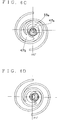
- Figure 5 shows the engaged state of the scrolls when the fluid is completely drawn into the sealed spaces 47a, 47b formed by both the circling and fixed scroll teeth and the upper fulcrum of the circulation diameter.
- Figure 6A shows the engaged state of scrolls at 0 degrees, in which if, immediately before the fluid is completely drawn in, the circling scroll is turned in the direction of arrow, the fluid is sealed in the spaces 47a, 47b.
- Denoted 48 is the sealed, compressed fluid before the circling scroll is turned. The compressed fluid is supplied from the delivery opening 33a in the fixed scroll to where it is used.
- Figure 6B is the engaged state at 90 degrees, in which the circling scroll has been turned 90 degrees from the state of Figure 6A.
- the fluid sealing spaces 47a, 47b are compressed and at the same time the scrolls already enter into the delivery stroke from the delivery opening 33a.
- Figure 6C represents the engaged state at 180 degrees, in which the fluid in the sealing spaces 47a, 47b is further compressed while being delivered from the delivery opening 33a.
- Figure 6D represents the engaged state at 270 degrees, in which the circling scroll has been turned another 90 degrees from the state of Figure 6C and almost all the fluid has been completely delivered. At the same time, the outer scroll tooth enters the process of forming a new sealing space.
- the boss bearing 38 is installed through the pin crank 42 at a position off-centered by a dimension S from the drive eccentric shaft 35.
- the pin crank base bearing 11 is installed in the frame 31, off-centered by a dimension K in the same eccentric direction as the drive eccentric shaft.
- the rotation prevention eccentric shaft 45 is mounted through bearings to the side of the circling scroll and to the bearing cover, off-centered by the same eccentricity as the pin crank.
- the pin crank 42 is built into the circling scroll boss 34a, the radial load acting on the circling scroll 34 is also borne by this bearing, which means that the circling scroll 34 is supported on both ends. This provides a sufficient support for the circling scroll 34 even when the scroll teeth width is large. Further, the provision of the boss wall 34b eliminates the possibility of the delivery pressure leaking to the suction side, thus maintaining a high volume efficiency.
- Figure 3 shows a two-stage type scroll fluid machine that makes use of the features of the two-block parallel operation.
- the two-stage type is suited for high-pressure compressors and high-vacuum pumps.
- the fluid drawn in from a first-stage intake opening 36 flows through a first-stage delivery opening 36a and is cooled by an intermediate cooler 47, from which it is again drawn into a second-stage intake opening 36b and supplied to a second-stage delivery opening 37.
- the pin crank 42 is shaped like a letter Z, the scroll block 33, 34 on the side of the right-hand drive eccentric shaft 35 is taken to be a first stage scroll block and the scroll block 33a, 34b on the left-hand side is taken to be a second stage.
- the compression ratios of each stage are made equal by adjusting the lengths of scroll teeth of each stage.
- the high-pressure compressors and vacuum pumps of reciprocal type, root type and two-stage type are complex, large and costly. The construction of this invention makes full use of the features of the scroll fluid machine in reducing the size and cost.
- Figure 4 shows another embodiment of this invention, which is a variation of the conventional scroll fluid machine with a cantilever bearing. That is, the boss 34a of the circling scroll 34 is supported at the left end by the pin crank 42. The circling scroll boss 34a performing the circling motion, therefore, is supported by bearings at both sides, improving the circling accuracy and allowing the scroll teeth length to be extended and the capacity to be increased.
- the dimension a of the circling scroll boss can be freely determined according to the size of the drive eccentric shaft and the bearing installed, and the scroll teeth is configured with a series of continuous arcs that can be chosen according to the pressure used.
- the internal end of the fixed scroll has a sealing shape that matches the oscillating motion of the circling scroll, thus providing a high level of sealing of fluid.
- bearings of grease-sealed type are used in this invention, it is possible to provide an oil-free scroll type fluid machine by forming a fine gap in the engagement between the scroll teeth.
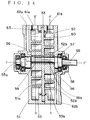
- Reference numeral 51 represents a left frame which accommodates bearings that support a subshaft 55a.
- the subshaft 55a is aligned with a drive shaft 55 and receives a drive eccentric shaft 55b.
- Designated 52 is a right frame which accommodates bearings 57, 58 to support the drive shaft 55.
- Denoted 53 is a mirror disk of a circling scroll having scroll teeth 53a, 53b on both sides. The scroll teeth 53a, 53b are positioned 180 degrees out of phase about the drive shaft 55 to achieve a weight balance between them.
- Figure 13 shows the position of the scroll tooth of the circling scroll.
- Denoted 54 is a key that securely and accurately fixes the engagement between the drive eccentric shaft 55b and the subshaft 55a.
- a delivery port 56 is provided to each of the left and right scroll teeth.
- Bearings 59 for the circling scroll are mounted rotatable.
- a plurality of pin cranks 60 are provided along the outer circumference of the circling scroll to prevent rotation of the scroll.
- the pin cranks 60 are off-centered by the same eccentricity as the drive eccentric shaft 55b.
- Denoted 61 is an intake port and 62 a delivery port.
- Symbol 51a signifies a fixed scroll tooth provided to the left frame, and 52b a fixed scroll tooth provided to the right frame.
- FIG 11 shows a cross section of the scroll teeth lap configuration taken along the line 12-12 of Figure 10.
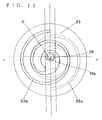
- Figure 12 shows a cross section of the scroll teeth lap configuration taken along the line 11-11 of Figure 10.
- Figure 13 shows the circling scroll as seen from the direction of the drive shaft 55, with X-X' representing the drive shaft axis and G representing the center.
- Figure 11 shows the engagement between the fixed scroll of the left frame and the left tooth of the circling scroll, with the center of the drive eccentric shaft 55b located at the center G1 that is off-centered by the eccentricity K from the drive shaft axis X-X'.
- G represents the center of the circling scroll, which has a boss with a radius of R1.
- the configuration of this scroll teeth conforms to that of the scroll type fluid machine of Japan Patent Application No. Heisei 6-169906, filed on June 17, 1994.
- the fixed scroll of the left frame that engages with the left tooth of the circling scroll has its center G2 downwardly off-centered by the same eccentricity K from the drive shaft axis and is defined by an arc having a radius Rla about the center G2. They engage as shown in Figure 11.
- the following relation holds: R1a R1+K+t.
- Figure 12 shows the engagement between the fixed scroll of the right frame and the right tooth of the circling scroll, with the center of the drive eccentric shaft 55b located at the center G1 that is off-centered upwardly by the eccentricity K from the drive shaft axis X-X'.
- G represents the center of the circling scroll.
- the boss of the right tooth with a radius of R1 unlike the left tooth of the circling scroll of Figure 11, is directed upwardly, that is, formed in the opposite direction to that of the left tooth, as shown in Figure 12.
- the configuration of the right tooth basically conforms to that defined in Japan Patent Application No. Heisei 6-169906 filed on June 17, 1994.
- the configuration of the fixed scroll of the right frame conforms to that defined in Japan Patent Application No. Heisei 6-169906 filed on June 17, 1994.
- Figure 13 shows the configuration of the circling scroll 53 as seen from the direction of the drive shaft 55, with the solid line 53b representing the right scroll tooth and the dashed line 53a representing the left scroll tooth.
- the circling scroll 53 is divided by an arbitrary line passing through the center G, the divided halves completely balance each other in weight.
- seals 63 are provided on both sides of the mirror disk of the circling scroll along the outer circumference at the contacting positions in order to form a two-way compression mechanism with suction ports 61a, 61b.
- This construction allows each scroll tooth to be used for different purposes. For example, one scroll tooth may be used as a compressor while the other is used as a vacuum pump.
- the circling scroll 53 has a left scroll tooth and a right scroll tooth separated from each other by the mirror disk and arranged 180 degrees out of phase.
- the right scroll tooth of Figure 12 is leading the left scroll tooth by 180 degrees in the compression stroke and the space F of Figure 12 is in the delivery stroke.
- the space F1 of Figure 11 is in the compression stroke.
- the conventional twin type has the left and right scroll teeth operate in the same strokes so that the spaces F both enter the delivery stroke at the same time. With the construction of this invention, however, the left and right scroll teeth alternately enter the suction stroke or delivery stroke, reducing the pulsation to half.
Landscapes
- Engineering & Computer Science (AREA)
- Mechanical Engineering (AREA)
- General Engineering & Computer Science (AREA)
- Rotary Pumps (AREA)
Applications Claiming Priority (4)
| Application Number | Priority Date | Filing Date | Title |
|---|---|---|---|
| JP169906/94 | 1994-06-17 | ||
| JP6169906A JP3016113B2 (ja) | 1994-06-17 | 1994-06-17 | スクロール型流体機械 |
| JP222382/94 | 1994-08-11 | ||
| JP22238294A JPH0861264A (ja) | 1994-08-11 | 1994-08-11 | バランス型スクロール流体機械 |
Publications (3)
| Publication Number | Publication Date |
|---|---|
| EP0687815A2 true EP0687815A2 (de) | 1995-12-20 |
| EP0687815A3 EP0687815A3 (de) | 1996-03-20 |
| EP0687815B1 EP0687815B1 (de) | 1998-11-18 |
Family
ID=26493101
Family Applications (1)
| Application Number | Title | Priority Date | Filing Date |
|---|---|---|---|
| EP95401383A Expired - Lifetime EP0687815B1 (de) | 1994-06-17 | 1995-06-14 | Spiralverdrängermaschine |
Country Status (3)
| Country | Link |
|---|---|
| US (1) | US5624247A (de) |
| EP (1) | EP0687815B1 (de) |
| DE (1) | DE69506036T2 (de) |
Cited By (6)
| Publication number | Priority date | Publication date | Assignee | Title |
|---|---|---|---|---|
| EP0798463A2 (de) * | 1996-03-29 | 1997-10-01 | Anest Iwata Corporation | Ölfreie Spiralvakuumpumpe |
| EP0863313A1 (de) * | 1997-03-04 | 1998-09-09 | Anest Iwata Corporation | Zweistufiger Spiralverdichter |
| EP1293676A2 (de) * | 2001-09-14 | 2003-03-19 | Sanden Corporation | Zweistufiger Spiralverdichter |
| EP1482177A1 (de) * | 2003-05-23 | 2004-12-01 | Anest Iwata Corporation | Spiralfluidmaschine |
| EP1489308A3 (de) * | 2003-06-20 | 2008-02-06 | Emerson Climate Technologies, Inc. | Mehrere Verdichter |
| CN107288875A (zh) * | 2017-07-24 | 2017-10-24 | 亿德机电科技(福建)有限公司 | 双作用旋偏心泵及其装配方法 |
Families Citing this family (28)
| Publication number | Priority date | Publication date | Assignee | Title |
|---|---|---|---|---|
| JP3194076B2 (ja) * | 1995-12-13 | 2001-07-30 | 株式会社日立製作所 | スクロール形流体機械 |
| US6014082A (en) * | 1997-10-03 | 2000-01-11 | Sony Corporation | Temperature monitoring and calibration system for control of a heated CVD chuck |
| JP3601770B2 (ja) | 1999-09-28 | 2004-12-15 | 株式会社豊田自動織機 | 燃料電池用圧縮回生機 |
| JP2001093554A (ja) * | 1999-09-28 | 2001-04-06 | Toyota Autom Loom Works Ltd | 燃料電池用圧縮回生機 |
| JP4424821B2 (ja) * | 2000-05-16 | 2010-03-03 | サンデン株式会社 | スクロール型圧縮機 |
| JP4031222B2 (ja) * | 2001-09-21 | 2008-01-09 | アネスト岩田株式会社 | スクロール式流体機械 |
| US6758659B2 (en) | 2002-04-11 | 2004-07-06 | Shimao Ni | Scroll type fluid displacement apparatus with fully compliant floating scrolls |
| US7467933B2 (en) * | 2006-01-26 | 2008-12-23 | Scroll Laboratories, Inc. | Scroll-type fluid displacement apparatus with fully compliant floating scrolls |
| US7371059B2 (en) * | 2006-09-15 | 2008-05-13 | Emerson Climate Technologies, Inc. | Scroll compressor with discharge valve |
| US7988433B2 (en) | 2009-04-07 | 2011-08-02 | Emerson Climate Technologies, Inc. | Compressor having capacity modulation assembly |
| US9651043B2 (en) | 2012-11-15 | 2017-05-16 | Emerson Climate Technologies, Inc. | Compressor valve system and assembly |
| US9249802B2 (en) | 2012-11-15 | 2016-02-02 | Emerson Climate Technologies, Inc. | Compressor |
| US9816506B2 (en) | 2013-07-31 | 2017-11-14 | Trane International Inc. | Intermediate oil separator for improved performance in a scroll compressor |
| US9790940B2 (en) | 2015-03-19 | 2017-10-17 | Emerson Climate Technologies, Inc. | Variable volume ratio compressor |
| US10598180B2 (en) | 2015-07-01 | 2020-03-24 | Emerson Climate Technologies, Inc. | Compressor with thermally-responsive injector |
| JP1574165S (de) * | 2016-08-31 | 2020-04-06 | ||
| JP1574166S (de) * | 2016-08-31 | 2020-04-06 | ||
| US10801495B2 (en) | 2016-09-08 | 2020-10-13 | Emerson Climate Technologies, Inc. | Oil flow through the bearings of a scroll compressor |
| US10890186B2 (en) | 2016-09-08 | 2021-01-12 | Emerson Climate Technologies, Inc. | Compressor |
| US10753352B2 (en) | 2017-02-07 | 2020-08-25 | Emerson Climate Technologies, Inc. | Compressor discharge valve assembly |
| US11022119B2 (en) | 2017-10-03 | 2021-06-01 | Emerson Climate Technologies, Inc. | Variable volume ratio compressor |
| US10962008B2 (en) | 2017-12-15 | 2021-03-30 | Emerson Climate Technologies, Inc. | Variable volume ratio compressor |
| US10995753B2 (en) | 2018-05-17 | 2021-05-04 | Emerson Climate Technologies, Inc. | Compressor having capacity modulation assembly |
| CN110878752B (zh) * | 2019-09-10 | 2021-08-24 | 郭辰 | 无倾覆动涡旋盘 |
| JP7380513B2 (ja) * | 2020-10-16 | 2023-11-15 | トヨタ自動車株式会社 | 車両用コンプレッサ搭載構造 |
| US11655813B2 (en) | 2021-07-29 | 2023-05-23 | Emerson Climate Technologies, Inc. | Compressor modulation system with multi-way valve |
| US11846287B1 (en) | 2022-08-11 | 2023-12-19 | Copeland Lp | Scroll compressor with center hub |
| US11965507B1 (en) | 2022-12-15 | 2024-04-23 | Copeland Lp | Compressor and valve assembly |
Citations (2)
| Publication number | Priority date | Publication date | Assignee | Title |
|---|---|---|---|---|
| JPS641674A (en) | 1987-06-22 | 1989-01-06 | Honda Motor Co Ltd | Manufacture of shell for fuel tank for motorcycle |
| JPH06169906A (ja) | 1992-12-10 | 1994-06-21 | Toshiba Corp | X線画像診断装置 |
Family Cites Families (14)
| Publication number | Priority date | Publication date | Assignee | Title |
|---|---|---|---|---|
| GB220296A (en) * | 1923-08-08 | 1925-01-08 | Luigi Nordi | Improvements in or relating to fluid pumps and the like |
| JPS57146085A (en) * | 1981-03-03 | 1982-09-09 | Sanden Corp | Scroll type fluid apparatus |
| JPS5923096A (ja) * | 1982-07-30 | 1984-02-06 | Toshiba Corp | スクロ−ル・コンプレツサ |
| US4677949A (en) * | 1985-08-19 | 1987-07-07 | Youtie Robert K | Scroll type fluid displacement apparatus |
| JPH01273891A (ja) * | 1988-04-23 | 1989-11-01 | Sanden Corp | うず巻体の製法 |
| JPH02182267A (ja) * | 1989-01-06 | 1990-07-16 | Oriental Kiden Kk | 点滴監視装置 |
| JPH02277985A (ja) * | 1989-04-20 | 1990-11-14 | Hitachi Ltd | スクロール形流体機械 |
| JPH0788822B2 (ja) * | 1989-04-20 | 1995-09-27 | 株式会社日立製作所 | オイルフリー式スクロール形流体機械 |
| US5171140A (en) * | 1990-10-19 | 1992-12-15 | Volkswagen Ag | Spiral displacement machine with angularly offset spiral vanes |
| JPH04365902A (ja) * | 1991-06-12 | 1992-12-17 | Mitsubishi Electric Corp | スクロール型流体機械 |
| JP2718295B2 (ja) * | 1991-08-30 | 1998-02-25 | ダイキン工業株式会社 | スクロール圧縮機 |
| EP0545190B1 (de) * | 1991-12-05 | 1996-05-29 | AGINFOR AG für industrielle Forschung | Verdrängermaschine nach dem Spiralprinzip |
| DE4215038A1 (de) * | 1992-05-07 | 1993-11-11 | Bitzer Kuehlmaschinenbau Gmbh | Spiralverdichter für kompressible Medien |
| DE4409343A1 (de) * | 1993-03-26 | 1994-09-29 | Volkswagen Ag | Verdränger für eine Spiralverdrängermaschine |
-
1995
- 1995-06-14 EP EP95401383A patent/EP0687815B1/de not_active Expired - Lifetime
- 1995-06-14 DE DE69506036T patent/DE69506036T2/de not_active Expired - Fee Related
- 1995-06-15 US US08/491,191 patent/US5624247A/en not_active Expired - Fee Related
Patent Citations (2)
| Publication number | Priority date | Publication date | Assignee | Title |
|---|---|---|---|---|
| JPS641674A (en) | 1987-06-22 | 1989-01-06 | Honda Motor Co Ltd | Manufacture of shell for fuel tank for motorcycle |
| JPH06169906A (ja) | 1992-12-10 | 1994-06-21 | Toshiba Corp | X線画像診断装置 |
Cited By (9)
| Publication number | Priority date | Publication date | Assignee | Title |
|---|---|---|---|---|
| EP0798463A2 (de) * | 1996-03-29 | 1997-10-01 | Anest Iwata Corporation | Ölfreie Spiralvakuumpumpe |
| EP0798463A3 (de) * | 1996-03-29 | 1998-02-25 | Anest Iwata Corporation | Ölfreie Spiralvakuumpumpe |
| EP0863313A1 (de) * | 1997-03-04 | 1998-09-09 | Anest Iwata Corporation | Zweistufiger Spiralverdichter |
| EP1293676A2 (de) * | 2001-09-14 | 2003-03-19 | Sanden Corporation | Zweistufiger Spiralverdichter |
| EP1293676A3 (de) * | 2001-09-14 | 2003-08-06 | Sanden Corporation | Zweistufiger Spiralverdichter |
| EP1482177A1 (de) * | 2003-05-23 | 2004-12-01 | Anest Iwata Corporation | Spiralfluidmaschine |
| EP1489308A3 (de) * | 2003-06-20 | 2008-02-06 | Emerson Climate Technologies, Inc. | Mehrere Verdichter |
| EP2048364A3 (de) * | 2003-06-20 | 2010-07-07 | Emerson Climate Technologies, Inc. | Mehrere Kompressoren mit Regelung der Fördermenge |
| CN107288875A (zh) * | 2017-07-24 | 2017-10-24 | 亿德机电科技(福建)有限公司 | 双作用旋偏心泵及其装配方法 |
Also Published As
| Publication number | Publication date |
|---|---|
| EP0687815A3 (de) | 1996-03-20 |
| DE69506036T2 (de) | 1999-06-10 |
| DE69506036D1 (de) | 1998-12-24 |
| EP0687815B1 (de) | 1998-11-18 |
| US5624247A (en) | 1997-04-29 |
Similar Documents
| Publication | Publication Date | Title |
|---|---|---|
| US5624247A (en) | Balance type scroll fluid machine | |
| US5447418A (en) | Scroll-type fluid machine having a sealed back pressure chamber | |
| JPH0610601A (ja) | スクロール型流体装置 | |
| KR20020034883A (ko) | 복수 실린더 로터리 압축기 | |
| US5788470A (en) | Fluid machine having two spiral working mechanisms with a stepped shape section | |
| KR20010035687A (ko) | 압축기 | |
| KR100192066B1 (ko) | 용적형 유체기계 | |
| JPH084672A (ja) | スクロール型流体機械 | |
| EP0866226B1 (de) | Verdrängungsfluidmachine | |
| EP1947292B1 (de) | Strömungmaschine mit kurbelwelle | |
| JPH07332258A (ja) | スクロール圧縮機 | |
| KR100408246B1 (ko) | 밀폐형 회전식 트윈 압축기의 토출구조 | |
| JP2003301784A (ja) | スクロール流体機械の自転防止機構 | |
| JP2001221169A (ja) | 複数連結式スクロール圧縮機 | |
| JP3059774B2 (ja) | スクロール圧縮機 | |
| JP2003035282A (ja) | スクロール型流体機械 | |
| JPH1137065A (ja) | 容積形流体機械 | |
| JP3066105B2 (ja) | 両回転型スクロール圧縮機 | |
| JPH06257580A (ja) | 2気筒回転圧縮機 | |
| JP3596063B2 (ja) | スクロール圧縮機 | |
| JPH05312160A (ja) | スクロール型流体装置 | |
| JP2023056437A (ja) | オイルフリー式スクロール圧縮機 | |
| KR100188999B1 (ko) | 유체기계 | |
| JPH0436083A (ja) | スクロール形流体機械 | |
| JPH02230992A (ja) | スクロール型流体装置 |
Legal Events
| Date | Code | Title | Description |
|---|---|---|---|
| PUAI | Public reference made under article 153(3) epc to a published international application that has entered the european phase |
Free format text: ORIGINAL CODE: 0009012 |
|
| AK | Designated contracting states |
Kind code of ref document: A2 Designated state(s): CH DE FR GB IT LI |
|
| PUAL | Search report despatched |
Free format text: ORIGINAL CODE: 0009013 |
|
| AK | Designated contracting states |
Kind code of ref document: A3 Designated state(s): CH DE FR GB IT LI |
|
| 17P | Request for examination filed |
Effective date: 19960531 |
|
| 17Q | First examination report despatched |
Effective date: 19970303 |
|
| GRAG | Despatch of communication of intention to grant |
Free format text: ORIGINAL CODE: EPIDOS AGRA |
|
| GRAG | Despatch of communication of intention to grant |
Free format text: ORIGINAL CODE: EPIDOS AGRA |
|
| GRAH | Despatch of communication of intention to grant a patent |
Free format text: ORIGINAL CODE: EPIDOS IGRA |
|
| GRAH | Despatch of communication of intention to grant a patent |
Free format text: ORIGINAL CODE: EPIDOS IGRA |
|
| GRAA | (expected) grant |
Free format text: ORIGINAL CODE: 0009210 |
|
| AK | Designated contracting states |
Kind code of ref document: B1 Designated state(s): CH DE FR GB IT LI |
|
| REG | Reference to a national code |
Ref country code: CH Ref legal event code: EP |
|
| REG | Reference to a national code |
Ref country code: CH Ref legal event code: NV Representative=s name: ROTTMANN, ZIMMERMANN + PARTNER AG |
|
| REF | Corresponds to: |
Ref document number: 69506036 Country of ref document: DE Date of ref document: 19981224 |
|
| ET | Fr: translation filed | ||
| ITF | It: translation for a ep patent filed | ||
| PGFP | Annual fee paid to national office [announced via postgrant information from national office to epo] |
Ref country code: GB Payment date: 19990609 Year of fee payment: 5 |
|
| PLBE | No opposition filed within time limit |
Free format text: ORIGINAL CODE: 0009261 |
|
| STAA | Information on the status of an ep patent application or granted ep patent |
Free format text: STATUS: NO OPPOSITION FILED WITHIN TIME LIMIT |
|
| 26N | No opposition filed | ||
| PG25 | Lapsed in a contracting state [announced via postgrant information from national office to epo] |
Ref country code: GB Free format text: LAPSE BECAUSE OF NON-PAYMENT OF DUE FEES Effective date: 20000614 |
|
| GBPC | Gb: european patent ceased through non-payment of renewal fee |
Effective date: 20000614 |
|
| PGFP | Annual fee paid to national office [announced via postgrant information from national office to epo] |
Ref country code: FR Payment date: 20010518 Year of fee payment: 7 |
|
| PGFP | Annual fee paid to national office [announced via postgrant information from national office to epo] |
Ref country code: CH Payment date: 20010530 Year of fee payment: 7 |
|
| PGFP | Annual fee paid to national office [announced via postgrant information from national office to epo] |
Ref country code: DE Payment date: 20010816 Year of fee payment: 7 |
|
| PG25 | Lapsed in a contracting state [announced via postgrant information from national office to epo] |
Ref country code: LI Free format text: LAPSE BECAUSE OF NON-PAYMENT OF DUE FEES Effective date: 20020630 Ref country code: CH Free format text: LAPSE BECAUSE OF NON-PAYMENT OF DUE FEES Effective date: 20020630 |
|
| PG25 | Lapsed in a contracting state [announced via postgrant information from national office to epo] |
Ref country code: DE Free format text: LAPSE BECAUSE OF NON-PAYMENT OF DUE FEES Effective date: 20030101 |
|
| REG | Reference to a national code |
Ref country code: CH Ref legal event code: PL |
|
| PG25 | Lapsed in a contracting state [announced via postgrant information from national office to epo] |
Ref country code: FR Free format text: LAPSE BECAUSE OF NON-PAYMENT OF DUE FEES Effective date: 20030228 |
|
| REG | Reference to a national code |
Ref country code: FR Ref legal event code: ST |
|
| PG25 | Lapsed in a contracting state [announced via postgrant information from national office to epo] |
Ref country code: IT Free format text: LAPSE BECAUSE OF NON-PAYMENT OF DUE FEES Effective date: 20050614 |