EP0686821B1 - Zweischichtkühler - Google Patents
Zweischichtkühler Download PDFInfo
- Publication number
- EP0686821B1 EP0686821B1 EP95105650A EP95105650A EP0686821B1 EP 0686821 B1 EP0686821 B1 EP 0686821B1 EP 95105650 A EP95105650 A EP 95105650A EP 95105650 A EP95105650 A EP 95105650A EP 0686821 B1 EP0686821 B1 EP 0686821B1
- Authority
- EP
- European Patent Office
- Prior art keywords
- cooler
- grate
- layer
- finished
- lower layer
- Prior art date
- Legal status (The legal status is an assumption and is not a legal conclusion. Google has not performed a legal analysis and makes no representation as to the accuracy of the status listed.)
- Expired - Lifetime
Links
Images


Classifications
-
- F—MECHANICAL ENGINEERING; LIGHTING; HEATING; WEAPONS; BLASTING
- F25—REFRIGERATION OR COOLING; COMBINED HEATING AND REFRIGERATION SYSTEMS; HEAT PUMP SYSTEMS; MANUFACTURE OR STORAGE OF ICE; LIQUEFACTION SOLIDIFICATION OF GASES
- F25D—REFRIGERATORS; COLD ROOMS; ICE-BOXES; COOLING OR FREEZING APPARATUS NOT OTHERWISE PROVIDED FOR
- F25D13/00—Stationary devices, e.g. cold-rooms
- F25D13/06—Stationary devices, e.g. cold-rooms with conveyors carrying articles to be cooled through the cooling space
-
- F—MECHANICAL ENGINEERING; LIGHTING; HEATING; WEAPONS; BLASTING
- F27—FURNACES; KILNS; OVENS; RETORTS
- F27D—DETAILS OR ACCESSORIES OF FURNACES, KILNS, OVENS, OR RETORTS, IN SO FAR AS THEY ARE OF KINDS OCCURRING IN MORE THAN ONE KIND OF FURNACE
- F27D15/00—Handling or treating discharged material; Supports or receiving chambers therefor
- F27D15/02—Cooling
- F27D15/0206—Cooling with means to convey the charge
- F27D15/0213—Cooling with means to convey the charge comprising a cooling grate
Definitions
- the invention relates to a two-layer cooler with a Grate surface, according to the preamble of the claim 1.
- a two-layer cooler of the type mentioned above is known for example from DE-C-10 97 346.
- this known cooler is at the drain end Grating (cooler end) as a separating device for separating at least one of the upper and lower refrigerated goods layers mechanical shovel arranged with its cutting edge engages directly in the refrigerated goods and this in a divides upper and lower layers.
- the essential The disadvantage of such a design is the high mechanical and thermal wear, which the in the cutting edge immersed in hot refrigerated goods and thus also the Bucket is exposed. This results in the known execution a considerable amount of maintenance and also a very undesirable susceptibility to failure.
- the invention is therefore based on the object Two-layer cooler in the preamble of claim 1 assumed type so that in the area of Separation device the freedom from maintenance and fault safety of the cooler can be significantly improved.
- This object is achieved in that at the cooler end as a separation device for separating the top and bottom refrigerated goods layer a stationary goods zone is provided, which is connected upstream of the crusher, flat inclined chute-like guide surface is.
- the separation device not by a separate mechanical element, but formed by a resting zone of the refrigerated goods is also affected in the area of the separating device inevitable wear alone between good particles moving relative to each other.
- abrasion is - unlike wear and tear mechanical cutting edge or shovel - by no means annoying, since the resulting fine particles be carried away with the finished goods and the dormant Goods zone automatically from the newly supplied material flow regenerated.
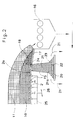
- FIG. 1 in a schematic overall view Two-layer cooler is used as a moving grate cooler formed, with successive rows of plates 1, 2 are arranged alternately stationary and movable.
- the plate rows of the cooler are divided into several groups 3, 4, 5 summarized, the separate fans 6 and 7 or 8, 9 with cooling air.
- a lower layer 10 is already on Pre-cooled goods to be cooled on the grate surface of the cooler given up.
- On this lower layer 10 is an upper Layer 11 of hot refrigerated goods applied.
- the pre-chilled Chilled goods of the lower layer 10 are placed over a Shaft 12 fed by a bunker wall 13 from a shaft 14 is separated, through which the hot Refrigerated goods - for example coming from a rotary kiln - applied to the lower layer 10 of the two-layer cooler becomes.
- a crusher 16 is furthermore arranged at the cooler end, which is connected upstream of a chute 17, which is the good of top layer 11 feeds the crusher 16.
- This chute 17 is inclined so flat that there is one on it dormant goods zone 18. It provides a separation device represents layers 10 and 11 at the end of the cooler separates from each other by dividing the good of the lower Retains layer 10 and into the finished goods shaft 15 conducts while the material of the upper layer 11 over the dormant goods zone 18 can slide away, so that it to Breaker 16 arrives.
- the crusher 16 coarser parts of the good crushed upper layer 11. After passing the crusher 16 the material of the upper layer 11 arrives as circulating material back to the beginning of the cooler (conveyor line 19) and is there as the lower layer 10 on the grate surface of the Abandoned cooler.
- the lower end of the finished goods chute 15 opens out Distance over a storage area 20 from a horizontally arranged table is formed. Its dimensions and its distance from the lower end of the finished goods chute 15 are chosen so that the bulk cone 21a of the finished goods emerging from the finished goods chute 15 21 on the surface of the storage surface 20 forming table opens into the edges of the table.
- a discharge member 22 is located in the storage surface 20 Direction of the double arrow 23 to and fro.
- the stroke speed and the stroke length of this as a bar trained discharge member 22 are changeable.
- the entrance opening of the finished goods chute 15 at the top is formed by a sieve or grate Classifier 24 covered.
- the finished goods chute 15 extends over the entire Width of the cooler (see Fig. 3). Its cross section widens towards the bottom (see Fig. 2).
- the grate plates are movable Plate rows 2 from a swing frame 25 worn, the back and forth in the direction of the double arrow 26 is movable while the plates of the rows of plates 1 are fixed.
- the last movable plate row 2a in the conveying direction is arranged so that it covers the area of the classifier 24 at least partially covered.
- the movable rows of plates 2 can in sections be connected to a channel that connects to the Swing frame 25 moves and a sliding seal is supplied with air.
- the lower layer 10 of pre-chilled goods protects the grille surface of the cooler from too high thermal stress and heavy wear by the hot refrigerated goods that form the upper layer 11.
- the two layers are covered by of the stationary goods zone 18 from each other Cut.
- a change in the strength of the top and lower layer is by adjusting the altitude the separator possible.
- the height of the resting goods zone 18 (and thus the thickness of the lower layer 10) by reduction the inclination of the chute 17 can be increased (and vice versa).
- Influencing the relative Layer thickness can also be increased, for example or lowering the chute 17 (with the same Chute inclination).
- Classifier 24 holds larger chunks of material, that are present in the lower layer 10. These chunks are then either autogenous Crushing in the material of the lower layer above the classification device 24, or they get into the dormant goods zone 18 or in the upper layer 11. Im in the latter case they pass crusher 16 again.
- the finished goods 21 jams on the storage surface 20 because the bulk cone 21a on the surface of the storage surface 20 forming tables within the table edges flows. Regardless of the existing one - in operation possibly changing - grain composition of the finished goods 21 is therefore the discharged amount of goods exclusively by the lifting speed and the Stroke length of the discharge member 22 determined.
- the last movable plate row 2a of the cooler has extended push edges so that the sieve bars of the Classifying device 24 completely or partially covered will. This will work even when using large attachments always get into the area of the classification device 24 at least the one through the last movable row of plates Keep the swept area clear during the return stroke. This area is so large that the quantity of material from the lower layer 10 passes through.
- the screening rods of the classification device 24 prevent that large pieces of good get into the finished goods chute 15. This way, constipation between the lower end of the finished goods chute 15 and the Storage surface 20 forming table avoided.
- the discharge member 22 designed as a bar becomes mechanical or hydraulically driven. It is convenient protected against wear by cast elements.
- the two partial flows of the finished product 21, which by the Discharge member 22 are conveyed away from the storage surface 20, can either - as indicated in Fig.1 - to a common conveyor line 27 summarized or separately to be transported further.
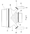
- FIG 5 shows a practical embodiment in a variant of the devices downstream of the crusher 16 for the discharge of the goods in circulation (i.e. the goods the upper layer 11).
- the crusher 16 is followed by a sieve grate 30, the Passage openings are dimensioned such that chopped goods are passed through the sieve grate, larger foreign objects (e.g. broken ones Rings of the crusher 16) are held back.
- larger foreign objects e.g. broken ones Rings of the crusher 16
- a chute 31 connects to the sieve grate 30, the one is the material in circulation (conveyor line 19 according to FIG. 1) a main outlet 32 feeding a transport device and two bypass outlets 33, 34. Through the latter two bypass outlets 33, 34 can be selected Cooled goods of the upper layer 11 are removed as finished goods will. It then arrives according to the conveyor line 28 (according to Fig.1) in the conveyor line 27 of the finished goods.
- the three outlets 32, 33 and 34 are through slide 35 up to 37 can be released or locked.
- the bypass outlets 33, 34 are also emergency routes Failure of a transport device for the circulating goods.
- bypass outlets 33, 34 are basic closed.
- the slides 36, 37 are opened and the slider 35 closed, the cooler can, if desired also operate in one shift.
- the property is erased into this case in the chute 31 as by the Good cone 38 indicated.
Description
- Fig.1
- eine schematische Gesamtansicht eines erfindungsgemäßen Zweischichtkühlers,
- Fig.2
- eine Teilansicht der für die Erfindung wesentlichen Elemente am Ende des Zweischichtkühlers gemäß Fig.1,
- Fig.3
- eine Aufsicht auf das Kühlerende,
- Fig.4
- eine Aufsicht auf Fertiggutschacht, Staufläche und Austragsorgan,
- Fig.5
- ein Detail einer Variante des Umlaufgutaustrages.
Claims (11)
- Zweischichtkühler mit einer Rostfläche, enthaltend,dadurch gekennzeichnet, daßa) am Kühleranfang vorgesehene Mittel (12, 14) zum Zuführen einer unteren Schicht (10) von bereits vorgekühltem Gut auf die Rost fläche sowie zum Aufbringen einer oberen Schicht (11) von heißem Gut auf die untere Kühlgutschicht (10),b) eine Trenneinrichtung (18, 17) am Kühlerende zum Trennen der beiden Kühlgutschichten (10, 11), wobeic) am Kühlerende zum Abziehen der unteren Kühlgutschicht eine Fertiggut-Abzugseinrichtung (15, 20, 22), zum Abführen der oberen Kühlgutschicht (11) ein Brecher (16) und eine Transporteinrichtung (19) zum Zurückführen des Gutes der oberen Schicht zum Kühleranfang vorgesehen sind, wo dieses zurückgeführte, vorgekühlte Kühlgut als untere Schicht (10) der Rostfläche aufgebbar ist,d) am Kühlerende als Trenneinrichtung zur Trennung der oberen und unteren Kühlgutschicht (10, 11) eine ruhende Gutzone (18) vorgesehen ist, die auf einer dem Brecher (16) vorgeschalteten, flach geneigten schurrenartigen Leitfläche (17) ausgebildet ist.
- Kühler nach Anspruch 1, dadurch gekennzeichnet, daß die Stärke der oberen und unteren Schicht (10, 11) durch Einstellung der Höhenlage der Trenneinrichtung (18) veränderlich ist.
- Kühler nach den Ansprüchen 1 und 2, dadurch gekennzeichnet, daß die Höhenlage der die Trenneinrichtung bildenden ruhenden Gutzone (18) durch Veränderung der Neigung der Leitfläche (17) einstellbar ist.
- Kühler nach Anspruch 1, dadurch gekennzeichnet, daß - in Bewegungsrichtung des Umlaufgutes betrachtet - nach dem Brecher (16) ein Siebrost (30) vorgesehen ist, dessen Durchlaßöffnungen derart bemessen sind, daß durch den Brecher (16) zerkleinertes Kühlgut den Siebrost passiert, größere Fremdkörper dagegen zurückgehalten werden.
- Kühler nach Anspruch 1, dadurch gekennzeichnet, daß sich an den Siebrost (30) eine Schurre (31) anschließt, die außer einem das Umlaufgut der Transporteinrichtung zuführenden Hauptauslaß (32) wenigstens einen wahlweise freigebbaren Bypassauslaß (33, 34) zum wahlweisen Abzug von Kühlgut der oberen Schicht (11) als Fertiggut aufweist.
- Kühler nach Anspruch 1, dadurch gekennzeichnet, daß am Kühlerende zum Abzug des Gutes der unteren Schicht (10) ein Fertiggutschacht (15) vorgesehen ist, dessen unteres Ende mit Abstand über einer Staufläche (20) ausmündet, längs der ein Austragsorgan (22) beweglich ist.
- Kühler nach Anspruch 6, dadurch gekennzeichnet, daß sich der Fertiggutschacht (15) über die gesamte Breite des Kühlers erstreckt und sich der Querschnitt des Fertiggutschachtes (15) nach unten zu erweitert.
- Kühler nach Anspruch 6, dadurch gekennzeichnet, daß die Staufläche (20) durch einen horizontal angeordneten Tisch gebildet wird, dessen Abmessungen und dessen Abstand vom unteren Ende des Fertiggutschachtes (15) so gewählt sind, daß der Schüttgutkegel (21a) des aus dem Fertiggutschacht (15) austretenden Gutes auf der Oberfläche des Tisches innerhalb der Tischränder mündet.
- Kühler nach Anspruch 6, dadurch gekennzeichnet, daß die Hubgeschwindigkeit und die Hublänge des als Balken ausgebildeten Austragsorganes (22) einstellbar sind.
- Kühler nach Anspruch 6, dadurch gekennzeichnet, daß die Eintrittsöffnung des Fertiggutschachtes (15) durch eine als Sieb oder Rost ausgebildete Klassiereinrichtung (24) abgedeckt ist.
- Kühler nach Anspruch 10, ausgebildet als Schubrostkühler, der vorzugsweise mit einzeln belüftbaren Rostplatten und/oder Rostplattenreihen versehen ist, wobei aufeinanderfolgende Plattenreihen abwechselnd stationär und beweglich angeordnet sind, dadurch gekennzeichnet, daß die in Förderrichtung letzte Plattenreihe beweglich ausgebildet und derart angeordnet ist, daß sie den Bereich der Klassiereinrichtung (24) wenigstens teilweise überstreicht.
Applications Claiming Priority (2)
| Application Number | Priority Date | Filing Date | Title |
|---|---|---|---|
| DE4419729A DE4419729A1 (de) | 1994-06-06 | 1994-06-06 | Zweischichtkühler |
| DE4419729 | 1994-06-06 |
Publications (2)
| Publication Number | Publication Date |
|---|---|
| EP0686821A1 EP0686821A1 (de) | 1995-12-13 |
| EP0686821B1 true EP0686821B1 (de) | 1998-09-16 |
Family
ID=6519902
Family Applications (1)
| Application Number | Title | Priority Date | Filing Date |
|---|---|---|---|
| EP95105650A Expired - Lifetime EP0686821B1 (de) | 1994-06-06 | 1995-04-13 | Zweischichtkühler |
Country Status (12)
| Country | Link |
|---|---|
| US (1) | US5715687A (de) |
| EP (1) | EP0686821B1 (de) |
| JP (1) | JPH07332825A (de) |
| KR (1) | KR960001692A (de) |
| AT (1) | ATE171264T1 (de) |
| BR (1) | BR9502635A (de) |
| DE (2) | DE4419729A1 (de) |
| DK (1) | DK0686821T3 (de) |
| ES (1) | ES2120654T3 (de) |
| TR (1) | TR28614A (de) |
| TW (1) | TW330982B (de) |
| ZA (1) | ZA953373B (de) |
Families Citing this family (3)
| Publication number | Priority date | Publication date | Assignee | Title |
|---|---|---|---|---|
| DE10113516A1 (de) * | 2001-03-20 | 2002-09-26 | Bmh Claudius Peters Gmbh | Verfahren und Vorrichtung zum Behandeln von Schüttgut |
| DE102018215348A1 (de) * | 2018-09-10 | 2020-03-12 | Thyssenkrupp Ag | Kühler zum Kühlen von Klinker und Verfahren zum Betreiben eines Kühlers zum Kühlen von Klinker |
| CN112444132B (zh) * | 2019-08-27 | 2022-08-30 | 湖北宜飞复合新材料有限公司 | 一种可提高生产效率的篦式冷却机头罩下料装置 |
Family Cites Families (6)
| Publication number | Priority date | Publication date | Assignee | Title |
|---|---|---|---|---|
| BE553427A (de) * | ||||
| DE1097346B (de) * | 1956-02-10 | 1961-01-12 | Smidth & Co As F L | Verfahren und Vorrichtung zum Kuehlen von klumpigem oder koernigem, aus einem Ofen kommendem Gut, z.B. Zementklinker |
| DE1303526B (de) * | 1964-09-03 | 1972-01-13 | Polysius Ag | |
| DE2064032A1 (en) * | 1970-12-28 | 1972-07-06 | Peters Ag Claudius | Two step cement clinker cooler - with double walled second stage oscillating channel conveyor cooler |
| US3831291A (en) * | 1972-08-16 | 1974-08-27 | Fuller Co | Method and apparatus for treatment of particulate material |
| DE3616630A1 (de) * | 1986-05-16 | 1987-11-19 | Krupp Polysius Ag | Kuehlvorrichtung |
-
1994
- 1994-06-06 DE DE4419729A patent/DE4419729A1/de not_active Withdrawn
-
1995
- 1995-04-13 EP EP95105650A patent/EP0686821B1/de not_active Expired - Lifetime
- 1995-04-13 ES ES95105650T patent/ES2120654T3/es not_active Expired - Lifetime
- 1995-04-13 DK DK95105650T patent/DK0686821T3/da active
- 1995-04-13 AT AT95105650T patent/ATE171264T1/de not_active IP Right Cessation
- 1995-04-13 DE DE59503580T patent/DE59503580D1/de not_active Expired - Fee Related
- 1995-04-26 TW TW084104124A patent/TW330982B/zh active
- 1995-04-26 ZA ZA953373A patent/ZA953373B/xx unknown
- 1995-05-17 JP JP7118324A patent/JPH07332825A/ja active Pending
- 1995-05-19 KR KR1019950012504A patent/KR960001692A/ko active IP Right Grant
- 1995-05-19 US US08/444,708 patent/US5715687A/en not_active Expired - Fee Related
- 1995-06-02 BR BR9502635A patent/BR9502635A/pt not_active IP Right Cessation
- 1995-06-05 TR TR00668/95A patent/TR28614A/xx unknown
Also Published As
| Publication number | Publication date |
|---|---|
| TW330982B (en) | 1998-05-01 |
| TR28614A (tr) | 1996-11-14 |
| ES2120654T3 (es) | 1998-11-01 |
| ATE171264T1 (de) | 1998-10-15 |
| EP0686821A1 (de) | 1995-12-13 |
| JPH07332825A (ja) | 1995-12-22 |
| ZA953373B (en) | 1996-01-11 |
| DE4419729A1 (de) | 1995-12-07 |
| DE59503580D1 (de) | 1998-10-22 |
| US5715687A (en) | 1998-02-10 |
| KR960001692A (ko) | 1996-01-25 |
| DK0686821T3 (da) | 1999-06-14 |
| BR9502635A (pt) | 1996-01-09 |
Similar Documents
| Publication | Publication Date | Title |
|---|---|---|
| EP1272803B2 (de) | Kühler und verfahren zum kühlen von heissem schüttgut | |
| DE2846941A1 (de) | Vorrichtung zur groessenaufteilung von korn- oder stueckfoermigem material | |
| EP0686821B1 (de) | Zweischichtkühler | |
| EP0482683B1 (de) | Verfahren und Vorrichtung zum Trennen eines Schüttgutstromes in Fraktionen mit unterschiedlicher Korngrösse | |
| EP0686819B1 (de) | Zweischichtkühler | |
| DE2837037C2 (de) | Drehtrommel-Luftstrom-Sortiervorrichtung zum Trennen von Feststoffgemischen wie Müll und dergleichen | |
| DE1482452C3 (de) | Windsichter mit mehreren mit Ab stand übereinander angeordneten, von Sichtluft quer durchströmten Sicht gruppen | |
| WO1994004276A1 (de) | Fördervorrichtung für beim wiederaufbereiten von restbeton anfallende zuschlagstoffe | |
| DE3013665A1 (de) | Einrichtung zur rohstoffwiedergewinnung oder -sortierung | |
| EP0686820A1 (de) | Zweischichtkühler | |
| DE3423474C1 (de) | Durchlaufbrecher | |
| DE102019215735A1 (de) | Kühler zum Kühlen von Schüttgut mit einer Stufe | |
| EP0640015A1 (de) | Anordnung zum brechen und kühlen des aus einem brennofen austretenden guts | |
| BE1027674B1 (de) | Kühler zum Kühlen von Schüttgut mit einer Stufe | |
| EP1206978A1 (de) | Vorrichtung zur Sortierung, Unterteilung einer Fraktion | |
| BE1027676B1 (de) | Verfahren und Kühler zum Kühlen von Schüttgut, insbesondere Zementklinker | |
| AT390569B (de) | Schlagwalzenbrecher | |
| DE3107812A1 (de) | Anlage zum vergleichmaessigen von brechgut, insbesondere kohle | |
| DE4040141C2 (de) | ||
| DE856402C (de) | Verfahren zur Erhoehung der Trennschaerfe eines Steigsichters und Steigsichter zur Durchfuehrung des Verfahrens | |
| DE19858767A1 (de) | Rostkühler | |
| DE1507685C (de) | Aufgabevornchtung fur einen Steig rohrsichter | |
| EP0636414A2 (de) | Kollergang | |
| DE1220597B (de) | Einrichtung zur Schuettung von Spanholz- od. dgl. -formlingen | |
| DE102019215738A1 (de) | Verfahren und Kühler zum Kühlen von Schüttgut, insbesondere Zementklinker |
Legal Events
| Date | Code | Title | Description |
|---|---|---|---|
| PUAI | Public reference made under article 153(3) epc to a published international application that has entered the european phase |
Free format text: ORIGINAL CODE: 0009012 |
|
| AK | Designated contracting states |
Kind code of ref document: A1 Designated state(s): AT BE CH DE DK ES FR GB GR IT LI NL PT SE |
|
| 17P | Request for examination filed |
Effective date: 19951031 |
|
| 17Q | First examination report despatched |
Effective date: 19970424 |
|
| GRAG | Despatch of communication of intention to grant |
Free format text: ORIGINAL CODE: EPIDOS AGRA |
|
| GRAG | Despatch of communication of intention to grant |
Free format text: ORIGINAL CODE: EPIDOS AGRA |
|
| GRAH | Despatch of communication of intention to grant a patent |
Free format text: ORIGINAL CODE: EPIDOS IGRA |
|
| GRAH | Despatch of communication of intention to grant a patent |
Free format text: ORIGINAL CODE: EPIDOS IGRA |
|
| GRAA | (expected) grant |
Free format text: ORIGINAL CODE: 0009210 |
|
| AK | Designated contracting states |
Kind code of ref document: B1 Designated state(s): AT BE CH DE DK ES FR GB GR IT LI NL PT SE |
|
| REF | Corresponds to: |
Ref document number: 171264 Country of ref document: AT Date of ref document: 19981015 Kind code of ref document: T |
|
| REG | Reference to a national code |
Ref country code: CH Ref legal event code: NV Representative=s name: BUGNION S.A. Ref country code: CH Ref legal event code: EP |
|
| REF | Corresponds to: |
Ref document number: 59503580 Country of ref document: DE Date of ref document: 19981022 |
|
| REG | Reference to a national code |
Ref country code: ES Ref legal event code: FG2A Ref document number: 2120654 Country of ref document: ES Kind code of ref document: T3 |
|
| ET | Fr: translation filed | ||
| GBT | Gb: translation of ep patent filed (gb section 77(6)(a)/1977) |
Effective date: 19990118 |
|
| REG | Reference to a national code |
Ref country code: PT Ref legal event code: SC4A Free format text: AVAILABILITY OF NATIONAL TRANSLATION Effective date: 19981118 |
|
| REG | Reference to a national code |
Ref country code: DK Ref legal event code: T3 |
|
| PLBE | No opposition filed within time limit |
Free format text: ORIGINAL CODE: 0009261 |
|
| STAA | Information on the status of an ep patent application or granted ep patent |
Free format text: STATUS: NO OPPOSITION FILED WITHIN TIME LIMIT |
|
| 26N | No opposition filed | ||
| PGFP | Annual fee paid to national office [announced via postgrant information from national office to epo] |
Ref country code: AT Payment date: 20010309 Year of fee payment: 7 |
|
| PGFP | Annual fee paid to national office [announced via postgrant information from national office to epo] |
Ref country code: FR Payment date: 20010312 Year of fee payment: 7 |
|
| PGFP | Annual fee paid to national office [announced via postgrant information from national office to epo] |
Ref country code: DK Payment date: 20010314 Year of fee payment: 7 |
|
| PGFP | Annual fee paid to national office [announced via postgrant information from national office to epo] |
Ref country code: SE Payment date: 20010319 Year of fee payment: 7 Ref country code: GB Payment date: 20010319 Year of fee payment: 7 Ref country code: CH Payment date: 20010319 Year of fee payment: 7 |
|
| PGFP | Annual fee paid to national office [announced via postgrant information from national office to epo] |
Ref country code: PT Payment date: 20010321 Year of fee payment: 7 |
|
| PGFP | Annual fee paid to national office [announced via postgrant information from national office to epo] |
Ref country code: NL Payment date: 20010322 Year of fee payment: 7 |
|
| PGFP | Annual fee paid to national office [announced via postgrant information from national office to epo] |
Ref country code: GR Payment date: 20010329 Year of fee payment: 7 |
|
| PGFP | Annual fee paid to national office [announced via postgrant information from national office to epo] |
Ref country code: ES Payment date: 20010406 Year of fee payment: 7 |
|
| PGFP | Annual fee paid to national office [announced via postgrant information from national office to epo] |
Ref country code: BE Payment date: 20010410 Year of fee payment: 7 |
|
| PGFP | Annual fee paid to national office [announced via postgrant information from national office to epo] |
Ref country code: DE Payment date: 20010503 Year of fee payment: 7 |
|
| REG | Reference to a national code |
Ref country code: GB Ref legal event code: IF02 |
|
| PG25 | Lapsed in a contracting state [announced via postgrant information from national office to epo] |
Ref country code: GB Free format text: LAPSE BECAUSE OF NON-PAYMENT OF DUE FEES Effective date: 20020413 Ref country code: AT Free format text: LAPSE BECAUSE OF NON-PAYMENT OF DUE FEES Effective date: 20020413 |
|
| PG25 | Lapsed in a contracting state [announced via postgrant information from national office to epo] |
Ref country code: SE Free format text: LAPSE BECAUSE OF NON-PAYMENT OF DUE FEES Effective date: 20020414 Ref country code: ES Free format text: LAPSE BECAUSE OF NON-PAYMENT OF DUE FEES Effective date: 20020414 |
|
| PG25 | Lapsed in a contracting state [announced via postgrant information from national office to epo] |
Ref country code: LI Free format text: LAPSE BECAUSE OF NON-PAYMENT OF DUE FEES Effective date: 20020430 Ref country code: DK Free format text: LAPSE BECAUSE OF NON-PAYMENT OF DUE FEES Effective date: 20020430 Ref country code: CH Free format text: LAPSE BECAUSE OF NON-PAYMENT OF DUE FEES Effective date: 20020430 Ref country code: BE Free format text: LAPSE BECAUSE OF NON-PAYMENT OF DUE FEES Effective date: 20020430 |
|
| PG25 | Lapsed in a contracting state [announced via postgrant information from national office to epo] |
Ref country code: PT Free format text: LAPSE BECAUSE OF NON-PAYMENT OF DUE FEES Effective date: 20021031 |
|
| PG25 | Lapsed in a contracting state [announced via postgrant information from national office to epo] |
Ref country code: NL Free format text: LAPSE BECAUSE OF NON-PAYMENT OF DUE FEES Effective date: 20021101 Ref country code: DE Free format text: LAPSE BECAUSE OF NON-PAYMENT OF DUE FEES Effective date: 20021101 |
|
| PG25 | Lapsed in a contracting state [announced via postgrant information from national office to epo] |
Ref country code: GR Free format text: LAPSE BECAUSE OF NON-PAYMENT OF DUE FEES Effective date: 20021105 |
|
| EUG | Se: european patent has lapsed |
Ref document number: 95105650.6 |
|
| GBPC | Gb: european patent ceased through non-payment of renewal fee |
Effective date: 20020413 |
|
| REG | Reference to a national code |
Ref country code: DK Ref legal event code: EBP |
|
| REG | Reference to a national code |
Ref country code: CH Ref legal event code: PL |
|
| PG25 | Lapsed in a contracting state [announced via postgrant information from national office to epo] |
Ref country code: FR Free format text: LAPSE BECAUSE OF NON-PAYMENT OF DUE FEES Effective date: 20021231 |
|
| NLV4 | Nl: lapsed or anulled due to non-payment of the annual fee |
Effective date: 20021101 |
|
| REG | Reference to a national code |
Ref country code: PT Ref legal event code: MM4A Free format text: LAPSE DUE TO NON-PAYMENT OF FEES Effective date: 20021031 |
|
| REG | Reference to a national code |
Ref country code: FR Ref legal event code: ST |
|
| REG | Reference to a national code |
Ref country code: ES Ref legal event code: FD2A Effective date: 20030514 |
|
| PG25 | Lapsed in a contracting state [announced via postgrant information from national office to epo] |
Ref country code: IT Free format text: LAPSE BECAUSE OF NON-PAYMENT OF DUE FEES Effective date: 20050413 |