EP0679551B1 - Lichteinheit für Kraftfahrzeuge - Google Patents
Lichteinheit für Kraftfahrzeuge Download PDFInfo
- Publication number
- EP0679551B1 EP0679551B1 EP95106181A EP95106181A EP0679551B1 EP 0679551 B1 EP0679551 B1 EP 0679551B1 EP 95106181 A EP95106181 A EP 95106181A EP 95106181 A EP95106181 A EP 95106181A EP 0679551 B1 EP0679551 B1 EP 0679551B1
- Authority
- EP
- European Patent Office
- Prior art keywords
- lamp
- reflector
- frame
- lamp unit
- headlamp
- Prior art date
- Legal status (The legal status is an assumption and is not a legal conclusion. Google has not performed a legal analysis and makes no representation as to the accuracy of the status listed.)
- Expired - Lifetime
Links
- 238000005192 partition Methods 0.000 claims description 27
- 238000010276 construction Methods 0.000 claims 1
- 230000002093 peripheral effect Effects 0.000 description 15
- 230000003287 optical effect Effects 0.000 description 3
- 238000000149 argon plasma sintering Methods 0.000 description 2
- 210000002414 leg Anatomy 0.000 description 2
- 230000007704 transition Effects 0.000 description 2
- 230000015572 biosynthetic process Effects 0.000 description 1
- 238000009434 installation Methods 0.000 description 1
- 238000000926 separation method Methods 0.000 description 1
- 239000007787 solid Substances 0.000 description 1
- 210000000689 upper leg Anatomy 0.000 description 1
Images
Classifications
-
- B—PERFORMING OPERATIONS; TRANSPORTING
- B60—VEHICLES IN GENERAL
- B60Q—ARRANGEMENT OF SIGNALLING OR LIGHTING DEVICES, THE MOUNTING OR SUPPORTING THEREOF OR CIRCUITS THEREFOR, FOR VEHICLES IN GENERAL
- B60Q1/00—Arrangement of optical signalling or lighting devices, the mounting or supporting thereof or circuits therefor
- B60Q1/0029—Spatial arrangement
- B60Q1/0041—Spatial arrangement of several lamps in relation to each other
-
- F—MECHANICAL ENGINEERING; LIGHTING; HEATING; WEAPONS; BLASTING
- F21—LIGHTING
- F21S—NON-PORTABLE LIGHTING DEVICES; SYSTEMS THEREOF; VEHICLE LIGHTING DEVICES SPECIALLY ADAPTED FOR VEHICLE EXTERIORS
- F21S43/00—Signalling devices specially adapted for vehicle exteriors, e.g. brake lamps, direction indicator lights or reversing lights
- F21S43/50—Signalling devices specially adapted for vehicle exteriors, e.g. brake lamps, direction indicator lights or reversing lights characterised by aesthetic components not otherwise provided for, e.g. decorative trim, partition walls or covers
-
- F—MECHANICAL ENGINEERING; LIGHTING; HEATING; WEAPONS; BLASTING
- F21—LIGHTING
- F21W—INDEXING SCHEME ASSOCIATED WITH SUBCLASSES F21K, F21L, F21S and F21V, RELATING TO USES OR APPLICATIONS OF LIGHTING DEVICES OR SYSTEMS
- F21W2103/00—Exterior vehicle lighting devices for signalling purposes
- F21W2103/10—Position lights
Definitions
- the invention relates to a light unit for motor vehicles, with a first and second headlights and one in Mounting position of the light unit above the first headlight arranged lamp, with one for the headlights and the Shine common pot-shaped housing, with a um at least one pivotable reflector of the first and second headlights and a reflector of the lamp, with a the reflector of the first headlight and the Reflector of the lamp covering together, bowl-shaped, translucent lens, which a peripheral side edge directed towards the housing has, with a frame supporting the lens, which encircling the outer edge of the case is attached and the shape and size of the Corresponding light exit openings of the reflectors Has openings and with one between the first Headlights and the lamp arranged opaque Partition, which is from the front of the Light unit seen up to close to the outer Side edges of the lens reach.
- the first light unit consists of essentially from a housing, from at least one in the Housing arranged pivotable reflector one Headlights and a bowl-shaped, translucent lens, which with its outer peripheral edge on the outer edge of the housing is attached and attached to it.
- the first Light unit is because of its only bowl-shaped, translucent lens only behind a single Body opening can be installed in the body and can be their installation to the front edge of the body opening be aligned that the cup-shaped lens with its front flush with that adjacent to it Outside of the body runs and that between the End window and the body opening all around same gap exists.
- the lens remains when the headlight reflectors swivel unchanged in their mounting position, as the reflectors with the Housing are connected.
- the second Light unit on two separate swiveling headlights each consisting essentially of a reflector and a translucent lens, which with its outer peripheral edge on the outer edge of the Reflector is placed and together with this one forms rigid unit.
- the two separate headlights can be swiveled with a common support frame connected.
- the second light unit can be behind two Body openings are inserted into the body, the two headlights with their lens in protrude one of the two body openings.
- Adjustment devices of the two headlights are not as with the first light unit protected in one housing arranged so that when installing the second light unit in the vehicle body the adjustment devices easily can be damaged. Should be the first and second Light unit a light, for example a flashing light, have, so this must be an additional part on the side be attached to the light unit. Between one translucent lens of the lamp and they would adjoin the headlamp lens then there is an annoying gap.
- German Patent No. 11 01 984 light unit of which we are known at the Formation of the preamble of claim 1 are assumed eliminated.
- the reflectors are the both headlights and the reflector of the lamp in one shared housing and the reflectors are together through a bowl-shaped cover plate covered.
- the lens is with its outer circumferential edge with the interposition of a ring seal placed on the outer peripheral edge of a frame and attached to it.
- the frame is again with his outer peripheral edge on the outer peripheral edge attached to the housing and releasably attached to it.
- the three reflectors of the light unit are in their mounting position arranged one above the other, the reflector of the lamp supreme is. In the frame is for each reflector introduced an opening.
- the reflector of the lamp lies with its outer peripheral edge on the edge of the upper Opening of the frame and is rigid with the frame connected while the two reflectors of the headlights with its outer circumferential edge with such a big game protrude into the opening that between them and the edge there is a visible gap in the respective opening.
- This Gap is necessary because of the opening in the frame protruding reflector of the headlights can be pivoted with is connected to the frame.
- the necessary Splits the light exit surface of the reflectors Headlights designed accordingly smaller than that Openings of the frame would allow it.
- the space between the Reflectors is taken up by the frame that supports them this must be inherently rigid.
- an opaque partition molded, which runs horizontally and is close to the side edges and the front of the bowl-shaped End plate extends.
- the opaque Partition serves on the one hand to shield light rays between the two separated by the partition Reflectors and on the other hand prevents the view from above on a light source below the partition arranged reflector of a headlight.
- one translucent disc which acts as a filter for the lamp serves on the edge of the reflector of the lamp receiving opening attached.
- the translucent Disc faces from the front of the light unit seen one of the light exit surface of the reflector appropriate size and runs with its front very close to the translucent lens. There between the translucent pane and the partition a gap and between the partition and the inside of the There is a separation point at a glance no harmonious picture through the lens given to the light unit. If the The lens and the frame supporting it must Reflectors and their adjustment devices also replaced become.
- a headlight is known from DE 41 08 007 A1, at which its reflector swivels with a housing connected is.
- a bowl-shaped, translucent The lens is in with its outer peripheral edge a receiving channel of a frame inserted and in this glued to the frame.
- the frame is again on the Housing facing side on its outer peripheral edge provided with a circumferential receiving channel, which for Inclusion of one on the outer peripheral edge of the housing adjacent ring seal is used.
- In the frame is one to to the side edges of the cup-shaped cover plate extending opening for the reflector introduced.
- On a collar is formed on the edge of the opening of the frame, which protrudes into the lens and with one free edge section towards the opening edge of the reflector is directed.
- the light unit known from DE 41 20 503 A1 for Motor vehicles are two headlights side by side arranged.
- the reflectors of the headlights are pivotally connected to the housing and by a common bowl-shaped, translucent lens covered.
- the lens is with its outer circumferential edge in an outer circumferential receiving channel a frame used.
- the frame is made of plastic manufactured and with its outer peripheral edge on the outer circumferential edge of the housing placed tightly.
- the Both headlight reflectors are behind each an opening of the frame arranged, in each of which one translucent pane is used.
- the well-known Light unit is not integrated and because of its light single cup-shaped cover plate not behind two Body openings can be inserted into the body.
- the Luminous efficacy of the headlights and the lamp is very high large because of the light emission surface of the three reflectors together is only slightly smaller than the lighting technology effective front of both bowl-shaped End plates together.
- the one on the edge of the two Openings of the frame molded collar covers one View through the front of the two lenses both against the direction of light emission Side edge of the cup-shaped lens as well between the edge of the opening of the frame and the outer Edge of the reflective space inside the interior of the reflectors Light unit off.
- the light unit does not build vertically high when the second headlight is next to the first one Headlight is arranged.
- the translucent lens is colorless and the inside the reflector of the lamp and the reflector of the first Headlights with an at least approximately the same looking shiny surface.
- the reflector of the lamp on the housing attached separate part and its lower side wall forms the partition, which with its free end portion extends into the opening of the edge and after directed downwards and so long that you free end section as a cover for one between the existing gap serves two reflectors.
- the front of the light unit seen approximately the free end of the partition congruent with the lower edge of the translucent Disc of the lamp runs.
- the partition with your as a cover serving free end section in its cross section in one Arch runs the convex side towards the lens is directed and both the up and to the End plate facing side of the partition of the Reflector of the lamp is provided with a surface, which has a high-gloss surface of the reflector Luminaire corresponds and merges into this, as well as the on molded the edges of the two openings of the frame Collar towards the front of the light unit sighted side is provided with a glossy surface, which looks like the shiny surface of the Reflectors approximately corresponds.
- the reflector of the lamp cannot be adjusted with the housing connected, it is advantageous if he deals with his outer peripheral edge to the edge of the opening of the frame molded collar extends. Advantageous it is still when the outer circumferential side wall of the Reflector of the lamp a section of a hollow cylinder or a hollow cone, and that between the reflector the lamp and the reflector of the first headlight running partition seen from the front runs arcuate, with its convex side upwards is directed. This is sufficient Luminous efficacy of the lamp a good luminous efficacy for the first headlamp, which is a dimmed headlamp can be given.
- the frame is on its The front of each one surrounding the openings Receiving channel and one on his back outer edge of the receiving channel for a ring seal has, except for the frame between the two Open wall section in cross section H-shaped is executed and the open sides of the H-shape form the respective receiving channel. This builds the frame in its height is very small and is still sufficient rigid connection.
- the two cup-shaped end plates by at least one wall section connecting them made in one piece. This allows the distance between the two cup-shaped end plates very close to each other can be tolerated and thus the light unit can be behind two Body openings are adjusted so that the two bowl-shaped light panes in the respective Body opening protrude and between the two translucent lenses and the on them adjacent body around an equally wide gap consists.
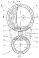
- the light unit for motor vehicles consists of a first one and second headlights (1, 2) and one in the mounting position of the Light unit above the first headlight (1) arranged lamp (3).
- the two headlights (1, 2) and the lamp (3) each have a bowl-shaped Reflector (4, 5 or 6).
- the reflectors (4, 5) of the Both headlights (1, 2) are side by side arranged and through a connecting wall (7) made in one piece.
- the two reflectors are over Adjustment devices (not shown) with one Plastic-made housing (9) connected. Through the Adjustments are the reflectors (4, 5) Headlights (1, 2) around a horizontal and vertical axis pivotable. One in the back of the case (9) introduced opening is through a cover (10) locked.
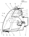
- the first headlight (1) is the bowl-shaped reflector (6) the lamp arranged, which with its back on the inside of the housing (9) by means of screws (12) is fixed immovably.
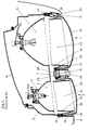
- the three reflectors (4, 5, 6) have a cylindrical side wall all around.
- the Reflectors (4, 5) of the headlight run with her outer edge in a plane which is approximately parallel to the Plane runs in which the housing (9) with its outer circumferential edge.
- the reflector (5) of the second Headlight (2) has a on its light exit surface circular circumference.
- the facing side wall sections of the Reflector (4) of the first headlight (1) and Reflector (6) of the lamp (3) are characterized by a small Gap (17) separated from each other.
- the small gap (17) seen from the front of the light unit almost horizontal and slightly bent upwards.
- the lower one delimiting the small gap (17) Side wall section of the reflector (6) of the lamp (3) protrudes in the light exit direction over the neighboring one Side edge of the reflector (4) of the first headlight (1) and runs with its front end portion (14) to Bent reflector (4).
- the lower side wall of the Reflector (6) of the lamp (3) is an opaque Partition (18) whose end portion (14) from the front the light unit seen to cover the between the serves two reflectors (4, 6) existing gap (17).
- the frame (21) is for the reflector (4) of the first Headlight (1) and the reflector (6) of the lamp (3) one common first opening (22) and for the reflector (5) of the second headlight (2) a second opening (23) brought in.
- the frame (21) is made of plastic and has on the side of the housing (9) on its outer All around the edge a receiving channel (24) into which one Ring seal is used.
- the frame (21) lies with the Ring seal close to the outer edge of the housing (9) and is releasably attached to the housing (9).
- the solvable Connection consists of self-locking holding elements and from overlapping holding elements of the housing (9) and of the frame (21), which is attached by a fastening screw the body part (8) can be fastened (not shown).
- the deep cup-shaped end plates (19, 20) are made of plastic and with the free end of it Side edges (25, 26) each in a receiving groove (27) glued in which the openings (22, 23) of the frame (21) surround.
- the frame (21) has both its two A wall section (28) connecting openings (22, 23) H-shaped cross-section, with one open Side of the H-shape, the receiving channel (24) for the ring seal and in the other open side of the H-shape the receiving channel (27) for the end disks (19, 20).
- Wall section (28) of the frame (21) is one upwards opened pocket, in which a Intermediate frame with a body arm (30) one Fastening element connecting the body part (8) (not shown) intervenes.
- the body arm (30) extends between the two cover disks (19, 20) and is one of a wall portion (not shown) trunk flap (32) above the light unit overlaps.
- the trunk lid (32) and the body part (8) thus together form two body openings in which protrude the two end plates (19, 20).
- an outer ring seal (33) To the Side edges (25, 26) of the cup-shaped end plates (19, 20) there is an outer ring seal (33), which over a web running between them are made in one piece.
- the ring seals (33) extended from the frame (21) in one Distance to the side edges (25 or 26) of the End disks (19 or 20) in the light exit direction and point at their free end two radially inwards directed lips (35).
- the lips (35) are at least so long that from the front of the light unit seen between the two body openings (33) and the end plate (19 or 20) protruding into it existing gap (17) is filled.
- the inner thigh the receiving channel (27) for the two end plates (19, 20) merges into a circumferential collar (36), which is deep into the cup-shaped cover plate (19, 20) stretched in and near their side edges (25 or 26) runs.
- the collars (36) have an edge section (34) on the outer edge of the cup-shaped reflectors (4, or 5) the headlights.
- the two collars (36) and the molded onto them edge portion (34) serve as Cover for between the frame (21) and the outer Edge of the reflectors (4, 5) existing gap.
- the collar is on the front of the light unit seeing side like the inside of the reflectors (4, 5, 6) and like that running between the reflectors (4, 5) Partition (18) provided with a glossy surface.
- the reflector (6) of the lamp protrudes with its partition (18) not just the reflector (4) of the first headlight (1), but also protrudes into the opening (22) of the frame (21) into it while having its top side wall in one Distance aligned behind the collar (36), which is in the Area of the reflector (6) of the lamp only in the end plate (19) projecting leg.
- the end portion (14) of the Partition (18) extends so far with its free end towards the bottom, so that it is the between the two reflectors (4, 5) covering the existing gap (17).
- the translucent Disc (31) is at the edge of the opening (23) of the frame (21) attached to the collar (36).
- In the reflector (6) of the lamp (3) is an opening for receiving a lamp (11) appropriate.
- the lamp (11) is from a yellow filter (not shown) surround.
Landscapes
- Engineering & Computer Science (AREA)
- General Engineering & Computer Science (AREA)
- Mechanical Engineering (AREA)
- Non-Portable Lighting Devices Or Systems Thereof (AREA)
- Nuclear Medicine (AREA)
- Lighting Device Outwards From Vehicle And Optical Signal (AREA)
Description
- der Reflektor des ersten und zweiten Scheinwerfers und der Leuchte ist an dem für die Scheinwerfer und die Leuchte gemeinsamen Gehäuse befestigt,
- in den Rahmen ist eine gemeinsame erste Öffnung für den Reflektor des ersten Scheinwerfers und den Reflektor der Leuchte und eine zweite Öffnung für den Reflektor des zweiten Scheinwerfers eingebracht,
- den beiden Öffnungen des Rahmens ist jeweils eine tiefe schalenförmige, lichtdurchlässige Abschlußscheibe zugeordnet, welche mit ihrem äußeren umlaufenden Rand an den Rand der jeweiligen Öffnung des Rahmens angrenzen,
- an den Rändern der beiden Öffnungen des Rahmens ist umlaufend ein Kragen angeformt, welcher in die schalenförmige Abschlußscheibe hineinragt und mit einem freien Randabschnitt auf den Umfangsrand der Reflektoren des Scheinwerfers zu gerichtet ist,
- der Reflektor der Leuchte und der Reflektor des ersten Scheinwerfers weisen eine gemeinsame Umfangslinie und benachbarte Seitenrandabschnitte auf, welche von der Vorderseite der Lichteinheit her gesehen bis zur Umfangslinie aneinander grenzen,
- die lichtundurchlässige Trennwand ist von einem Seitenrand der sich benachbarten Reflektoren des ersten Scheinwerfers und der Leuchte gebildet.
- Figur 1
- eine Vorderseite einer Lichteinheit für Kraftfahrzeuge, mit zwei seitlich nebeneinander angeordneten Scheinwerfern und mit einer über einem Scheinwerfer angeordneten Leuchte;
- Figur 2
- einen vertikalen Schnitt nach der Linie A-A durch die Leuchte und den unter ihr angeordneten Scheinwerfer und
- Figur 3
- einen horizontalen Schnitt nach der Linie B-B durch die seitlich nebeneinander angeordneten Scheinwerfer.
- 1
- erster Scheinwerfer
- 2
- zweiter Scheinwerfer
- 3
- Leuchte
- 4
- Reflektor
- 5
- Reflektor
- 6
- Reflektor
- 7
- Wand
- 8
- Karosserieteil
- 9
- Gehäuse
- 10
- Deckel
- 11
- Lampe
- 12
- Schraube
- 13
- Spalt
- 14
- Endabschnitt
- 15
- Wandabschnitt
- 16
- Umfangslinie
- 17
- Spalt
- 18
- Trennwand
- 19
- Abschlußscheibe
- 20
- Abschlußscheibe
- 21
- Rahmen
- 22
- Öffnung
- 23
- Öffnung
- 24
- Aufnahmerinne
- 25
- Seitenrand
- 26
- Seitenrand
- 27
- Aufnahmerinne
- 28
- Wandabschnitt
- 29
- Tasche
- 30
- Karosserieteil
- 31
- Scheibe
- 32
- Kofferraumklappe
- 33
- Ringdichtung
- 34
- Randabschnitt
- 35
- Lippe
- 36
- Kragen
Claims (13)
- Lichteinheit für Kraftfahrzeuge mit einem ersten und zweiten Scheinwerfer (1, 2) und einer in Anbaulage der Lichteinheit oberhalb des ersten Scheinwerfers (1) angeordneten Leuchte (3), mit einem für die Scheinwerfer (1, 2) und die Leuchte (3) gemeinsamen topfförmigen Gehäuse (9), mit einem um mindestens eine Achse verschwenkbaren Reflektor (4, 5) des ersten und zweiten Scheinwerfers (1, 2) und einem Reflektor (6) der Leuchte (3) mit einer den Reflektor (4) des ersten Scheinwerfers (1) und des Reflektors (6) der Leuchte (3) gemeinsam abdeckenden, schalenförmigen, lichtdurchlässigen Abschlußscheibe (19), welche einen zum Gehäuse (9) hin gerichteten umlaufenden Seitenrand (25) aufweist, mit einem die Abschlußscheibe (19) tragenden Rahmen (21), welcher umlaufend an dem äußeren Rand des Gehäuses (9) aufgesetzt ist und der Form und Größe der Lichtaustrittsöffnungen der Reflektoren (4, 5, 6) entsprechende Öffnungen (22, 23) aufweist, und mit einer zwischen dem ersten Scheinwerfer (1) und der Leuchte (3) angeordneten lichtundurchlässigen Trennwand (18), welche von der Vorderseite der Lichteinheit her gesehen bis nahe an die äußeren Seitenränder (25) der Abschlußscheibe (19) heranreicht,
gekennzeichnet durch folgende Merkmale:der Reflektor (4, 5 bzw. 6) des ersten und zweiten Scheinwerfers (1, 2) und der Leuchte (3) ist an dem für die Scheinwerfer (1, 2) und die Leuchte (3) gemeinsamen Gehäuse (9) befestigt,in den Rahmen (21) ist eine gemeinsame erste Öffnung (22) für den Reflektor (4) des ersten Scheinwerfers (1) und dem Reflektor (6) der Leuchte (3) und eine zweite Öffnung (23) für den Reflektor (5) des zweiten Scheinwerfers (2) eingebracht,den beiden Öffnungen (22, 23) des Rahmens (21) ist jeweils eine tiefe schalenförmige, Lichtdurchlässige Abschlußscheibe (19 bzw. 20) zugeordnet, welche mit ihrem äußeren umlaufenden Rand an den Rand der jeweiligen Öffnung (22 bzw. 23) des Rahmen (21) angrenzen,an den Rändern der beiden Öffnungen (22, 23) des Rahmens (21) ist umlaufend ein Kragen (36) angeformt, welcher in die schalenförmige Abschlußscheibe (19 bzw. 20) hineinragt und mit einem freien Randabschnitt (34) auf den Umfangsrand des Reflektors (4 bzw. 5) des Scheinwerfers (1, 2) zugerichtet ist,der Reflektor (6) der Leuchte (3) und der Reflektor (4) des ersten Scheinwerfers (1) weisen eine gemeinsame Umfangslinie (16) und benachbarte Seitenwandabschnitte auf, welche von der Vorderseite der Lichteinheit her gesehen bis zu der Umfangslinie (16) hin aneinander grenzen,die lichtundurchlässige Trennwand (18) ist von einer Seitenwand der sich benachbarten Reflektoren (5, 6) des ersten Scheinwerfers (1) und der Leuchte (3) gebildet. - Lichteinheit nach Anspruch 1, mit einer lichtdurchlässigen Scheibe (31), welche zwischen dem Reflektor (6) der Leuchte (3) und der Abschlußscheibe (19) angeordnet ist, an dem Rahmen (21) befestigt ist und von der Vorderseite der Lichteinheit her gesehen, die gesamte Lichtaustrittsfläche des Reflektors (6) der Leuchte (3) abdeckt, dadurch gekennzeichnet, daß die lichtdurchlässige Scheibe (31) von der Vorderseite der Lichteinheit her gesehen, sich bis zur oberen Seitenwand des Reflektors (4) des ersten Scheinwerfers (1) hin erstreckt.
- Lichteinheit nach Anspruch 1 oder 2, dadurch gekennzeichnet, daß die zwischen der Leuchte (3) und dem ersten Scheinwerfer (1) verlaufende Trennwand (18) mit ihrem freien Endabschnitt sich bis in die Öffnung (22) des Rahmens (21) hineinerstreckt.
- Lichteinheit nach einem der Ansprüche 1 bis 3, dadurch gekennzeichnet, daß der Reflektor (6) der Leuchte (3) ein an dem Gehäuse (9) befestigtes separates Teil ist und seine untere Seitenwand die Trennwand (18) bildet, welche mit ihrem freien Endabschnitt (14) nach unten hin gerichtet und so lang ausgeführt ist, daß ihr freier Endabschnitt (14) als Abdeckung für einen zwischen den beiden Reflektoren (4, 6) bestehenden Spalt (17) dient.
- Lichteinheit nach Anspruch 4, dadurch gekennzeichnet, daß die Trennwand (18) mit ihrem als Abdeckung dienenden freien Endabschnitt (14) in ihren in Lichtaustrittsrichtung verlaufenden Querschnitten in einem Bogen verläuft, dessen konvexe Seite zur Abschlußsscheibe (19) hin gerichtet ist.
- Lichteinheit nach einem der Ansprüche 1 bis 5, dadurch gekennzeichnet, daß die nach oben und zur Abschlußscheibe (19) hin gerichtete Seite der Trennwand (18) des Reflektors (6) mit einer Oberfläche versehen ist, welche einer glänzenden Oberfläche des Reflektors (6) der Leuchte (3) entspricht und in diese übergeht und daß der an die Ränder der beiden Öffnungen (22, 23) des Rahmens (21) angeformte Kragen (36) auf den von der Vorderseite der Lichteinheit zu sehenden Seite mit einer glänzenden Oberfläche versehen ist, welche dem Aussehen nach der glänzenden Oberfläche der Reflektoren (4, 5, 6) annähernd entspricht.
- Lichteinheit nach einem der Ansprüche 1 bis 6, dadurch gekennzeichnet, daß der an die Ränder der Öffnung (22, 23) des Rahmens (21) angeformte Kragen (36) im Bereich des Reflektors (4, 5) des ersten und zweiten Scheinwerfers (1, 2) im Querschnitt V-förmige ausgeführt ist, wobei die V-Form mit ihrem Scheitel in Lichtaustrittsrichtung weist und im Bereich des Reflektors (6) der Leuchte (3) ausschließlich ein in die Abschlußscheibe (19) hineinragender Schenkel ist.
- Lichteinheit nach Anspruch 4, dadurch gekennzeichnet, daß der Reflektor (6) der Leuchte (3) mit seiner oberen Seitenwand entgegen der Lichtaustrittsrichtung gesehen, annähernd fluchtend hinter dem Kragen (36) liegt.
- Lichteinheit nach einem der Ansprüche 1 bis 8, dadurch gekennzeichnet, daß die äußere umlaufende Seitenwand des Reflektors (6) der Leuchte (3) ein Abschnitt eines Hohlzylinders bzw. eines Hohlkegels ist.
- Lichteinheit nach einem der Ansprüche 1 bis 9, dadurch gekennzeichnet, daß die zwischen den Reflektoren (6) der Leuchte (3) und dem Reflektor (4) des ersten Scheinwerfers (1) verlaufende Trennwand (18) von der Vorderseite der Lichteinheit her gesehen, bogenförmig verläuft, wobei ihre konvexe Seite nach oben hin gerichtet ist.
- Lichteinheit nach einem der Ansprüche 1 bis 10, dadurch gekennzeichnet, daß die beiden schalenförmigen Abschlußscheiben (19, 20) mit ihrem umlaufenden äußeren Rand an dem Rand der Öffnungen (22, 23) des Rahmens (21) anliegen und mit diesem verklebt sind und daß der Rahmen (21) dicht an dem äußeren Rand des Gehäuses (9) anliegt und mit diesem lösbar verbunden ist.
- Lichteinheit nach Anspruch 11, dadurch gekennzeichnet, daß der Rahmen (21) auf seiner Außenseite jeweils eine die Öffnungen (22, 23) umgebene Aufnahmerinne (27) und auf seiner Rückseite eine an seinem äußeren Rand umlaufende Aufnahmerinne (24) für eine Ringdichtung aufweist, wobei der Rahmen (21) bis auf den zwischen beiden Öffnungen (22, 23) verlaufenden Wandabschnitt (28) im Querschnitt H-förmig ausgeführt ist und die offenen Seiten der H-Form die jeweilige Aufnahmerinne (27 bzw. 24) bilden.
- Lichteinheit nach einem der Ansprüche 1 bis 12, dadurch gekennzeichnet, daß die beiden schalenförmigen Abschlußscheiben (19, 20) durch mindestens einen sie verbindenden Wandabschnitt (15) einstückig hergestellt sind.
Priority Applications (1)
| Application Number | Priority Date | Filing Date | Title |
|---|---|---|---|
| SI9530284T SI0679551T1 (en) | 1994-04-28 | 1995-04-26 | Lighting unit for vehicle |
Applications Claiming Priority (2)
| Application Number | Priority Date | Filing Date | Title |
|---|---|---|---|
| DE4414898 | 1994-04-28 | ||
| DE4414898A DE4414898C1 (de) | 1994-04-28 | 1994-04-28 | Lichteinheit für Kraftfahrzeuge |
Publications (3)
| Publication Number | Publication Date |
|---|---|
| EP0679551A2 EP0679551A2 (de) | 1995-11-02 |
| EP0679551A3 EP0679551A3 (de) | 1996-05-22 |
| EP0679551B1 true EP0679551B1 (de) | 1999-08-11 |
Family
ID=6516713
Family Applications (1)
| Application Number | Title | Priority Date | Filing Date |
|---|---|---|---|
| EP95106181A Expired - Lifetime EP0679551B1 (de) | 1994-04-28 | 1995-04-26 | Lichteinheit für Kraftfahrzeuge |
Country Status (4)
| Country | Link |
|---|---|
| EP (1) | EP0679551B1 (de) |
| DE (2) | DE4414898C1 (de) |
| ES (1) | ES2136764T3 (de) |
| SI (1) | SI0679551T1 (de) |
Cited By (2)
| Publication number | Priority date | Publication date | Assignee | Title |
|---|---|---|---|---|
| DE10048382A1 (de) * | 2000-09-29 | 2002-04-11 | Volkswagen Ag | Fahrzeugscheinwerfer und Reflektoreinheit hierfür |
| WO2024023302A1 (fr) * | 2022-07-28 | 2024-02-01 | Valeo Vision | Élément optique d'un module d'éclairage et de signalisation lumineuse |
Families Citing this family (5)
| Publication number | Priority date | Publication date | Assignee | Title |
|---|---|---|---|---|
| FR2732748B1 (fr) * | 1995-04-06 | 1997-06-20 | Valeo Vision | Bloc optique a boitier comportant un projecteur et un feu de signalisation |
| DE19830257A1 (de) * | 1998-07-07 | 2000-01-27 | Hella Kg Hueck & Co | Fahrzeugscheinwerfer |
| DE19853872A1 (de) * | 1998-11-23 | 2000-05-25 | Hella Kg Hueck & Co | Lichteinheit für Fahrzeuge |
| DE19961859A1 (de) | 1999-12-22 | 2001-06-28 | Hella Kg Hueck & Co | Fahrzeugscheinwerfer |
| FR3082153B1 (fr) * | 2018-06-11 | 2022-08-05 | Psa Automobiles Sa | Bloc optique pour vehicule automobile pourvu d’un masque chausse sur au moins un reflecteur |
Family Cites Families (5)
| Publication number | Priority date | Publication date | Assignee | Title |
|---|---|---|---|---|
| DE1101984B (de) * | 1958-06-28 | 1961-03-09 | Westfaelische Metall Ind K G H | Leuchteinheit fuer Kraftfahrzeuge |
| DE3328788A1 (de) * | 1983-08-10 | 1985-02-28 | Bosch Gmbh Robert | Scheinwerfer fuer kraftfahrzeuge |
| DE3417041C2 (de) * | 1984-05-09 | 1986-03-20 | Audi AG, 8070 Ingolstadt | Einrichtung zur Befestigung einer Beleuchtungseinheit an einer Kraftfahrzeugkarosserie |
| IT1240148B (it) * | 1990-03-23 | 1993-11-27 | Carello Spa | Proiettore per veicoli, in particolare autoveicoli. |
| DE4120503A1 (de) * | 1991-06-21 | 1992-12-24 | Bosch Gmbh Robert | Scheinwerfereinheit fuer kraftfahrzeuge |
-
1994
- 1994-04-28 DE DE4414898A patent/DE4414898C1/de not_active Expired - Fee Related
-
1995
- 1995-04-26 DE DE59506560T patent/DE59506560D1/de not_active Expired - Fee Related
- 1995-04-26 SI SI9530284T patent/SI0679551T1/xx unknown
- 1995-04-26 ES ES95106181T patent/ES2136764T3/es not_active Expired - Lifetime
- 1995-04-26 EP EP95106181A patent/EP0679551B1/de not_active Expired - Lifetime
Cited By (4)
| Publication number | Priority date | Publication date | Assignee | Title |
|---|---|---|---|---|
| DE10048382A1 (de) * | 2000-09-29 | 2002-04-11 | Volkswagen Ag | Fahrzeugscheinwerfer und Reflektoreinheit hierfür |
| DE10048382B4 (de) * | 2000-09-29 | 2010-07-08 | Volkswagen Ag | Fahrzeugscheinwerfer und Reflektoreinheit hierfür |
| WO2024023302A1 (fr) * | 2022-07-28 | 2024-02-01 | Valeo Vision | Élément optique d'un module d'éclairage et de signalisation lumineuse |
| FR3138495A1 (fr) * | 2022-07-28 | 2024-02-02 | Valeo Vision | Bloc optique d’un module d’éclairage et de signalisation lumineuse |
Also Published As
| Publication number | Publication date |
|---|---|
| DE59506560D1 (de) | 1999-09-16 |
| SI0679551T1 (en) | 1999-12-31 |
| ES2136764T3 (es) | 1999-12-01 |
| EP0679551A2 (de) | 1995-11-02 |
| EP0679551A3 (de) | 1996-05-22 |
| DE4414898C1 (de) | 1995-07-20 |
Similar Documents
| Publication | Publication Date | Title |
|---|---|---|
| EP0955207B1 (de) | Mehrkammerleuchte für Fahrzeuge | |
| EP1914118A2 (de) | Aussenrückspiegel mit Leuchtmittel | |
| DE4417695A1 (de) | Kraftfahrzeugleuchte | |
| DE69931019T2 (de) | Optisches system für kraftfahrzeuge | |
| DE19824053A1 (de) | Beleuchtungseinrichtung für Fahrzeuge | |
| EP0679551B1 (de) | Lichteinheit für Kraftfahrzeuge | |
| DE19635521A1 (de) | Lampenabdeckung für eine Außenleuchte, insbesondere Mast-Aufsetzleuchte | |
| DE102004018695A1 (de) | Außenrückblickspiegel für Fahrzeuge, vorzugsweise Kraftfahrzeuge | |
| DE19519655B4 (de) | An einem Frontteil eines Fahrzeugs angeordnete Beleuchtungseinrichtung | |
| DE3306481A1 (de) | Lichtabgabevorrichtung fuer kraftfahrzeuge | |
| DE19721596C2 (de) | Leuchte, insbesondere Heckleuchte, für Fahrzeuge, vorzugsweise Kraftfahrzeuge | |
| EP1004473B1 (de) | Lichteinheit für Fahrzeuge | |
| DE10121387C2 (de) | Leuchteinheit mit einem Erkennungszeichen für Kraftfahrzeuge | |
| DE60304132T2 (de) | Beleuchtungs- und/oder Signaleinrichtung für Kfz mit einem Abdeckteil | |
| DE29614796U1 (de) | Scheinwerfer mit wahlweise daran montierter Scheinwerfer-Waschvorrichtung | |
| DE4445272A1 (de) | In einem Frontteil eines Fahrzeugs angeordnete Beleuchtungseinrichtung | |
| DE4414899C1 (de) | Abdeckeinheit für ein Reflektoren aufnehmendes Gehäuse einer Lichteinheit für Kraftfahrzeuge | |
| EP0696703A1 (de) | Scheinwerfer für Fahrzeuge | |
| DE19838911B4 (de) | Beleuchtungseinrichtung eines Fahrzeugs | |
| DE4237162C1 (de) | Scheinwerfer-Leuchten-Einheit für Kraftfahrzeuge | |
| DE1497316A1 (de) | Beleuchtungskoerper mit Rueckstrahlvorrichtung | |
| DE3922830A1 (de) | Leuchte, insbesondere fuer kraftfahrzeuge | |
| DE19933714B4 (de) | Leuchte mit zweiter Lichtquelle | |
| DE10253271A1 (de) | Fahrzeugleuchte zur Anordnung in einem Karosserieausschnitt | |
| DE9417304U1 (de) | Fahrzeugleuchte |
Legal Events
| Date | Code | Title | Description |
|---|---|---|---|
| PUAI | Public reference made under article 153(3) epc to a published international application that has entered the european phase |
Free format text: ORIGINAL CODE: 0009012 |
|
| AK | Designated contracting states |
Kind code of ref document: A2 Designated state(s): DE ES FR IT |
|
| RAX | Requested extension states of the european patent have changed |
Free format text: SI PAYMENT 950505 |
|
| PUAL | Search report despatched |
Free format text: ORIGINAL CODE: 0009013 |
|
| AK | Designated contracting states |
Kind code of ref document: A3 Designated state(s): DE ES FR IT |
|
| AX | Request for extension of the european patent |
Free format text: SI PAYMENT 950505 |
|
| 17P | Request for examination filed |
Effective date: 19960926 |
|
| RAP1 | Party data changed (applicant data changed or rights of an application transferred) |
Owner name: DAIMLER-BENZ AKTIENGESELLSCHAFT Owner name: HELLA KG HUECK & CO. |
|
| GRAG | Despatch of communication of intention to grant |
Free format text: ORIGINAL CODE: EPIDOS AGRA |
|
| GRAG | Despatch of communication of intention to grant |
Free format text: ORIGINAL CODE: EPIDOS AGRA |
|
| GRAH | Despatch of communication of intention to grant a patent |
Free format text: ORIGINAL CODE: EPIDOS IGRA |
|
| 17Q | First examination report despatched |
Effective date: 19990127 |
|
| RAP1 | Party data changed (applicant data changed or rights of an application transferred) |
Owner name: DAIMLERCHRYSLER AG Owner name: HELLA KG HUECK & CO. |
|
| GRAH | Despatch of communication of intention to grant a patent |
Free format text: ORIGINAL CODE: EPIDOS IGRA |
|
| ITF | It: translation for a ep patent filed | ||
| GRAA | (expected) grant |
Free format text: ORIGINAL CODE: 0009210 |
|
| AK | Designated contracting states |
Kind code of ref document: B1 Designated state(s): DE ES FR IT |
|
| AX | Request for extension of the european patent |
Free format text: SI PAYMENT 19950505 |
|
| REF | Corresponds to: |
Ref document number: 59506560 Country of ref document: DE Date of ref document: 19990916 |
|
| ET | Fr: translation filed | ||
| REG | Reference to a national code |
Ref country code: ES Ref legal event code: FG2A Ref document number: 2136764 Country of ref document: ES Kind code of ref document: T3 |
|
| PLBE | No opposition filed within time limit |
Free format text: ORIGINAL CODE: 0009261 |
|
| STAA | Information on the status of an ep patent application or granted ep patent |
Free format text: STATUS: NO OPPOSITION FILED WITHIN TIME LIMIT |
|
| 26N | No opposition filed | ||
| PGFP | Annual fee paid to national office [announced via postgrant information from national office to epo] |
Ref country code: ES Payment date: 20020410 Year of fee payment: 8 |
|
| PGFP | Annual fee paid to national office [announced via postgrant information from national office to epo] |
Ref country code: FR Payment date: 20020423 Year of fee payment: 8 |
|
| PG25 | Lapsed in a contracting state [announced via postgrant information from national office to epo] |
Ref country code: ES Free format text: LAPSE BECAUSE OF NON-PAYMENT OF DUE FEES Effective date: 20030428 |
|
| PG25 | Lapsed in a contracting state [announced via postgrant information from national office to epo] |
Ref country code: FR Free format text: LAPSE BECAUSE OF NON-PAYMENT OF DUE FEES Effective date: 20031231 |
|
| REG | Reference to a national code |
Ref country code: FR Ref legal event code: ST |
|
| PGFP | Annual fee paid to national office [announced via postgrant information from national office to epo] |
Ref country code: DE Payment date: 20040506 Year of fee payment: 10 |
|
| REG | Reference to a national code |
Ref country code: ES Ref legal event code: FD2A Effective date: 20030428 |
|
| PG25 | Lapsed in a contracting state [announced via postgrant information from national office to epo] |
Ref country code: IT Free format text: LAPSE BECAUSE OF NON-PAYMENT OF DUE FEES;WARNING: LAPSES OF ITALIAN PATENTS WITH EFFECTIVE DATE BEFORE 2007 MAY HAVE OCCURRED AT ANY TIME BEFORE 2007. THE CORRECT EFFECTIVE DATE MAY BE DIFFERENT FROM THE ONE RECORDED. Effective date: 20050426 |
|
| PG25 | Lapsed in a contracting state [announced via postgrant information from national office to epo] |
Ref country code: DE Free format text: LAPSE BECAUSE OF NON-PAYMENT OF DUE FEES Effective date: 20051101 |