EP1004473B1 - Lichteinheit für Fahrzeuge - Google Patents
Lichteinheit für Fahrzeuge Download PDFInfo
- Publication number
- EP1004473B1 EP1004473B1 EP99121836A EP99121836A EP1004473B1 EP 1004473 B1 EP1004473 B1 EP 1004473B1 EP 99121836 A EP99121836 A EP 99121836A EP 99121836 A EP99121836 A EP 99121836A EP 1004473 B1 EP1004473 B1 EP 1004473B1
- Authority
- EP
- European Patent Office
- Prior art keywords
- reflectors
- lighting unit
- cover section
- housing
- light lamp
- Prior art date
- Legal status (The legal status is an assumption and is not a legal conclusion. Google has not performed a legal analysis and makes no representation as to the accuracy of the status listed.)
- Expired - Lifetime
Links
- 239000000463 material Substances 0.000 claims description 2
- 238000007789 sealing Methods 0.000 claims 5
- 230000001747 exhibiting effect Effects 0.000 claims 1
- 230000003287 optical effect Effects 0.000 description 7
- 239000010410 layer Substances 0.000 description 2
- 230000002093 peripheral effect Effects 0.000 description 2
- 241000396922 Pontia daplidice Species 0.000 description 1
- 230000001154 acute effect Effects 0.000 description 1
- 239000003086 colorant Substances 0.000 description 1
- 238000004519 manufacturing process Methods 0.000 description 1
- 239000002344 surface layer Substances 0.000 description 1
Images

Classifications
-
- B—PERFORMING OPERATIONS; TRANSPORTING
- B60—VEHICLES IN GENERAL
- B60Q—ARRANGEMENT OF SIGNALLING OR LIGHTING DEVICES, THE MOUNTING OR SUPPORTING THEREOF OR CIRCUITS THEREFOR, FOR VEHICLES IN GENERAL
- B60Q1/00—Arrangement of optical signalling or lighting devices, the mounting or supporting thereof or circuits therefor
- B60Q1/0029—Spatial arrangement
- B60Q1/0041—Spatial arrangement of several lamps in relation to each other
-
- F—MECHANICAL ENGINEERING; LIGHTING; HEATING; WEAPONS; BLASTING
- F21—LIGHTING
- F21W—INDEXING SCHEME ASSOCIATED WITH SUBCLASSES F21K, F21L, F21S and F21V, RELATING TO USES OR APPLICATIONS OF LIGHTING DEVICES OR SYSTEMS
- F21W2103/00—Exterior vehicle lighting devices for signalling purposes
- F21W2103/10—Position lights
Definitions
- the invention relates to a light unit for vehicles, in particular headlights for Motor vehicles, with a housing with an entire front of the housing covering dish-shaped cover lens, which is at least optics-free Has areas with at least two arranged in the housing bowl-shaped reflectors, which are in one piece via a first cover part are interconnected, and with a second cover, which between the reflectors and the lens and in the mounting position of the light unit surrounds at least the reflectors below and with two side legs and which, together with the first cover part, provides a view of the interior of the light unit shields.
- Such a light unit for vehicles is known from FR - A - 2 709 810.
- the Headlight has a housing, the front opening through a Cover plate is covered, which is approximately at right angles to the longitudinal side of the vehicle runs.
- Two bowl-shaped reflectors arranged in the housing are through connecting their front edges an integral part. Exclusively in upper edges, the edges are in one piece via a first cover part connected with each other. Both reflectors have one in the lower area Flattening on the front edge of the light exit opening of the reflectors limited.
- the length of the second cover part, starting from the reflectors, is free Edge towards the lens. Furthermore, the second cover protrudes into the cup-shaped reflectors and covers their flattening, thus between the second cover part and the reflectors do not show a disturbing gap.
- the Assembly of the separate second cover part is cumbersome and time-consuming when attaching the cover to the reflectors, the sensitive Reflecting surface of the reflectors can be damaged.
- a light unit for vehicles is known from EP-A1-0 646 495 A1 in the case of two in a plastic housing bowl-shaped reflectors are arranged side by side.
- the reflectors can be adjusted by adjusting devices around a horizontal and vertical axis.
- a cover Between the reflectors and one that covers the front of the housing Cover plate is a cover, which has a gap between the Reflectors and the front edge of the case covers.
- the disadvantage here is that the cover part is a separate part and by means of fastening screws with the Is to be connected.
- Another known light unit for A separate cover is attached to the lens while vehicles another cover part two reflectors arranged side by side integrally connected with each other (DE 44 14 898 C1). This does exist for both Reflectors common adjustment devices, however, is still the separate one Cover part costly to manufacture and cumbersome and time consuming assemble.
- the light unit for vehicles known from US 5,140,504 has two Cover part connecting reflectors for receiving a position light lamp.
- the cover parts can be used together with the reflectors with a reflective Layer.
- the second cover runs at least below the Reflectors, because for a viewer in front of the vehicle especially in this area an existing between the reflectors and the front edge of the housing Gap would disturb.
- a gap can be shielded between the inner reflector arranged towards the center of the vehicle and the neighboring one lateral front edge of the housing is made, while through to the back of the housing pointing other side leg of the first cover part largely the gap that can be shielded between that of the vehicle's long side adjacent outer reflector and the front edge of the housing.
- the torsional rigidity of the reflectors and cover parts Unit is particularly large if the second cover part is in an area above the reflectors point with a section to the rear of the housing. Thereby is the second cover part frame-like and to the surrounding Reflectors and the first cover part molded.
- the reflectors and the position light lamp should be so close to the lens be arranged so that the treads of the steps of the steps receiving the reflectors first cover part with at least a third of its extent into the interior extend into a cup-shaped cover plate. This can be a between the housing or the cover plate and the second cover part remaining gap can be made very small, and yet is sufficient
- the reflectors can be adjusted around a horizontal and vertical axis.
- the position light lamp needs very little space between the reflectors take when the position light lamp above or below a horizontal center plane of the light unit is arranged. This is particularly the case with Given reflectors that have a circular light exit opening. Furthermore, it is advantageous if a reflector of the position light lamp is in one piece is executed with the first cover part and the reflector by a Lens is covered.
- the lens can be with optical elements be provided which scatter on the light of the position light lamp.
- housing made of a material with a light color. This will appear for a viewer between the second cover and the front edge remaining small gap of the housing bright, without the inside of the Housing with an additional bright surface layer to be applied must be provided.
- a light color for the housing z. B. white or light gray. Such colors have a high degree of reflection.
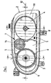
- a headlight for motor vehicles serves as a light unit for vehicles, which recessed in a body opening of the vehicle (not ) Shown.
- the headlight has a cup-shaped made of plastic Housing (1) on.
- the housing (1) has an opening on its back provided, which is closed by a housing cap (16).
- a bowl-shaped cover plate (2) is placed, which with your peripheral edge tightly with the front edge (17) of the housing (1) connected is.
- the front lens (2) is free of on its front side optical elements, while the inside of its peripheral side wall (18) has a structured surface (19).
- Inside the headlight is one optical unit mounted adjustable around a horizontal and vertical axis.
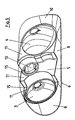
- the optical unit consists of two arranged side by side Reflectors (3, 4), a position light lamp (7) and a first and second Cover part (5, 6).
- the reflectors (3, 4) have a circular shape Light exit surface and are bowl-shaped. In the crown area the reflectors (3, 4) is an opening for receiving a lamp (20 or 21) brought in.
- the first cover part (5) has several steps, their treads (11) run vertically and transversely to the light exit direction.
- the first cover part (5) has three treads (11).
- In the middle tread (11) of the first Cover part (5) is the position light lamp (7) above the horizontal Center plane (12) of the headlamp.
- the position light lamp (7) has an annular, cup-shaped reflector (13), which in one piece with the first cover part (5).
- the bowl-shaped reflector (13) is through a lens (14) with vertically extending optical elements covered. At least the outer reflectors (3, 4) Treads (11) protrude into the cup-shaped cover plate (2).
- the main lens (2) extends at an acute angle with its main extension ⁇ to the adjacent longitudinal side of the vehicle (not shown).
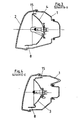
- a frame-like second cover part (6) is molded all around.
- the L-shaped section exists consisting of a long leg and a short leg (8, 9).
- the second Cover part (6) dips with its L-shaped section into the bowl-shaped End plate (2) on.
- the second frame-like cover part (6) faces laterally of the reflector (4) a short leg (10) and above the first Cover part (5) a section (15).
- the short leg (10) and the Section (15) point to the rear of the headlamp.
- the one from the reflectors (3, 4, 13) and the first and second cover parts (5 and 6) existing optical Unit is on its entire front with a reflective layer Mistake. Between the optical unit and the front edge (17) of the There is a small gap (22) all around the housing (1).
- the gap (22) appears bright on the outside and therefore not annoying, since the housing is a bright one Color plastic is made.
Landscapes
- Engineering & Computer Science (AREA)
- Mechanical Engineering (AREA)
- Non-Portable Lighting Devices Or Systems Thereof (AREA)
- Lighting Device Outwards From Vehicle And Optical Signal (AREA)
Description
- sich ausgehend von dem ersten Abdeckteil (5) zur Abschlussscheibe (2) hin erstreckt,
- zusammen mit dem ersten Abdeckteil (5), den Reflektoren (3, 4) und einer Aufnahme des ersten Abdeckteils (5) für eine Positionslichtlampe (7) ein einstückiges Teil ist und
- im Bereich eines seitlichen Schenkels (9) zur Abschlussscheibe (2) und im Bereich des anderen seitlichen Schenkels (9) zur Rückseite des Gehäuses (1) hin weist und
- 1
- Gehäuse
- 2
- Abschlußscheibe
- 3
- Reflektor
- 4
- Reflektor
- 5
- erstes Abdeckteil
- 6
- zweites Abdeckteil
- 7
- Positionslichtlampe
- 8
- langer Schenkel
- 9
- kurzer Schenkel
- 10
- kurzer Schenkel
- 11
- Trittflächen
- 12
- Mittelebene
- 13
- Reflektor
- 14
- Lichtscheibe
- 15
- Abschnitt
- 16
- Gehäusekappe
- 17
- vorderer Rand
- 18
- Seitenwand
- 19
- strukturierte Oberfläche
- 20
- Lampe
- 21
- Lampe
- 22
- Spalt
Claims (7)
- Lichteinheit für Fahrzeuge, insbesondere Scheinwerfer für Kraftfahrzeuge, mit einem Gehäuse (1), mit einer die gesamte Vorderseite des Gehäuses (1) abdeckenden schalenförmigen Abschlussscheibe (2), welche zumindest optikfreie Bereiche aufweist, mit mindestens zwei in dem Gehäuse (1) angeordneten schalenförmigen Reflektoren (3, 4), welche über ein erstes Abdeckteil (5) einstückig miteinander verbunden sind, und mit einem zweiten Abdeckteil (6), welches zwischen den Reflektoren (3, 4) und der Abschlussscheibe (2) und in der Anbaulage der Lichteinheit zumindest die Reflektoren (3, 4) unterhalb und mit zwei seitlichen Schenkeln (9,10) umgibt und welches zusammen mit dem ersten Abdeckteil (5) die Sicht in das Innere der Lichteinheit abschirmt, dadurch gekennzeichnet, dassa) das zweite Abdeckteil (6)sich ausgehend von dem ersten Abdeckteil (5) zur Abschlussscheibe (2) hin erstreckt,zusammen mit dem ersten Abdeckteil (5), den Reflektoren (3, 4) und einer Aufnahme des ersten Abdeckteils (5) für eine Positionslichtlampe (7) ein einstückiges Teil ist undim Bereich eines seitlichen Schenkels (9) zur Abschlussscheibe (2) und im Bereich des anderen seitlichen Schenkels (9) zur Rückseite des Gehäuses (1) hin weist undb) das erste Abdeckteil (5) stufenförmig gestaltet ist, wobei die Trittflächen (11) der Stufen vertikal und quer zur Lichtaustrittsrichtung verlaufen und die Reflektoren (3, 4) und die Positionslichtlampe (7) aufnehmen.
- Lichteinheit für Fahrzeuge nach Anspruch 1, dadurch gekennzeichnet, dass das zweite Abdeckteil (6) in einem Bereich oberhalb der Reflektoren (3, 4) mit einem Abschnitt (15) zur Rückseite des Gehäuses hin weist.
- Lichteinheit für Fahrzeuge nach Anspruch 1 oder 2, dadurch gekennzeichnet, dass die die Reflektoren (3, 4) aufnehmenden Trittflächen (11) der Stufen des ersten Abdeckteils (5) mit mindestens einem Drittel ihrer Ausdehnung sich in das Innere einer schalenförmigen Abschlussscheibe (2) hinein erstrecken.
- Lichteinheit für Fahrzeuge nach einem der Ansprüche 1 bis 3, dadurch gekennzeichnet, dass die Positionslichtlampe (7) oberhalb oder unterhalb einer horizontalen Mittelebene (12) der Lichteinheit angeordnet ist.
- Lichteinheit für Fahrzeuge nach einem der Ansprüche 1 bis 4, dadurch gekennzeichnet, dass ein Reflektor (13) der Positionslichtlampe (7) einstückig mit dem ersten Abdeckteil (5) ausgeführt ist.
- Lichteinheit für Fahrzeuge nach einem der Ansprüche 1 bis 5, dadurch gekennzeichnet, dass der Reflektor (13) der Positionslichtlampe (7) durch eine Lichtscheibe (14) abgedeckt ist.
- Lichteinheit für Fahrzeuge nach einem der Ansprüche 1 bis 6, dadurch gekennzeichnet, dass das Gehäuse (1) aus einem eine helle Farbe aufweisenden Werkstoff besteht.
Applications Claiming Priority (2)
| Application Number | Priority Date | Filing Date | Title |
|---|---|---|---|
| DE19853872 | 1998-11-23 | ||
| DE19853872A DE19853872A1 (de) | 1998-11-23 | 1998-11-23 | Lichteinheit für Fahrzeuge |
Publications (3)
| Publication Number | Publication Date |
|---|---|
| EP1004473A2 EP1004473A2 (de) | 2000-05-31 |
| EP1004473A3 EP1004473A3 (de) | 2002-12-04 |
| EP1004473B1 true EP1004473B1 (de) | 2004-05-12 |
Family
ID=7888643
Family Applications (1)
| Application Number | Title | Priority Date | Filing Date |
|---|---|---|---|
| EP99121836A Expired - Lifetime EP1004473B1 (de) | 1998-11-23 | 1999-11-04 | Lichteinheit für Fahrzeuge |
Country Status (3)
| Country | Link |
|---|---|
| EP (1) | EP1004473B1 (de) |
| DE (2) | DE19853872A1 (de) |
| ES (1) | ES2221290T3 (de) |
Families Citing this family (6)
| Publication number | Priority date | Publication date | Assignee | Title |
|---|---|---|---|---|
| NL1015769C2 (nl) * | 2000-07-21 | 2002-01-22 | Spanninga Metaal | Koplamp voor een fiets of bromfiets. |
| DE10052653A1 (de) * | 2000-10-24 | 2002-05-02 | Volkswagen Ag | Beleuchtungsanordnung für Kraftfahrzeuge |
| FR2840387B1 (fr) * | 2002-05-31 | 2005-01-07 | Valeo Vision | Dispositif d'eclairage et/ou de signalisation pour vehicule comprenant un masque |
| DE10258293A1 (de) * | 2002-12-13 | 2004-06-24 | Hella Kg Hueck & Co. | Beleuchtungseinrichtung für Fahrzeuge |
| DE102005004637B4 (de) * | 2004-03-01 | 2015-04-16 | Volkswagen Ag | Scheinwerfer oder Leuchte, insbesondere für Kraftfahrzeuge, und Verfahren zur Herstellung einer Blenden-Reflektor-Kombination |
| FR3002305A1 (fr) * | 2013-02-15 | 2014-08-22 | Peugeot Citroen Automobiles Sa | Ecran multifonctions pour un bloc optique multifonctions de vehicule |
Family Cites Families (6)
| Publication number | Priority date | Publication date | Assignee | Title |
|---|---|---|---|---|
| JPH0782761B2 (ja) * | 1990-09-26 | 1995-09-06 | 株式会社小糸製作所 | クリアランスランプ一体型自動車用ヘッドランプ |
| JP2610088B2 (ja) * | 1993-03-08 | 1997-05-14 | 株式会社小糸製作所 | 補助ランプ内蔵自動車用ヘッドランプ |
| JPH06283002A (ja) * | 1993-03-26 | 1994-10-07 | Koito Mfg Co Ltd | 自動車用ヘッドランプ |
| FR2709810B1 (fr) * | 1993-09-09 | 1995-12-01 | Valeo Vision | Projecteur d'aspect intérieur amélioré pour véhicule automobile. |
| JP3335228B2 (ja) | 1993-09-30 | 2002-10-15 | 本田技研工業株式会社 | 車両用前照灯装置 |
| DE4414898C1 (de) * | 1994-04-28 | 1995-07-20 | Hella Kg Hueck & Co | Lichteinheit für Kraftfahrzeuge |
-
1998
- 1998-11-23 DE DE19853872A patent/DE19853872A1/de not_active Withdrawn
-
1999
- 1999-11-04 EP EP99121836A patent/EP1004473B1/de not_active Expired - Lifetime
- 1999-11-04 DE DE59909461T patent/DE59909461D1/de not_active Expired - Lifetime
- 1999-11-04 ES ES99121836T patent/ES2221290T3/es not_active Expired - Lifetime
Also Published As
| Publication number | Publication date |
|---|---|
| DE19853872A1 (de) | 2000-05-25 |
| DE59909461D1 (de) | 2004-06-17 |
| EP1004473A2 (de) | 2000-05-31 |
| ES2221290T3 (es) | 2004-12-16 |
| EP1004473A3 (de) | 2002-12-04 |
Similar Documents
| Publication | Publication Date | Title |
|---|---|---|
| DE19508472C2 (de) | Fahrzeugscheinwerfer mit einer Anzahl von Leuchten | |
| EP0955207B1 (de) | Mehrkammerleuchte für Fahrzeuge | |
| DE10100176B4 (de) | Leuchte mit einer Reflektoranordnung mit mehreren Reflexionsflächen, insbesondere für ein Kraftfahrzeug | |
| DE19922142C2 (de) | Kraftfahrzeugscheinwerfer | |
| DE19824053A1 (de) | Beleuchtungseinrichtung für Fahrzeuge | |
| DE19907765A1 (de) | Verbesserte Einheit aus mindestens einem Scheinwerfer und einer Signalleuchte für ein Automobil | |
| EP0745511B1 (de) | Beleuchtungseinrichtung für Fahrzeuge | |
| DE69401314T2 (de) | Stylistisches oder optisches Element- mit glänzendem Aussehen und neutraler Farbe- für Kfz-Beleuchtungs- oder Anzeige-Scheinwerfer | |
| EP1004473B1 (de) | Lichteinheit für Fahrzeuge | |
| DE19507585C2 (de) | Scheinwerfer-Leuchten-Einheit für Fahrzeuge | |
| DE19519655B4 (de) | An einem Frontteil eines Fahrzeugs angeordnete Beleuchtungseinrichtung | |
| DE19543008B4 (de) | Kraftfahrzeugscheinwerfer mit einem unterteilten Reflektor | |
| DE19602978B4 (de) | Fahrzeug-Scheinwerfer | |
| DE4414898C1 (de) | Lichteinheit für Kraftfahrzeuge | |
| DE3628441C2 (de) | Abblendlichtscheinwerfer für Kraftfahrzeuge | |
| DE19838911B4 (de) | Beleuchtungseinrichtung eines Fahrzeugs | |
| EP0474806B1 (de) | Scheinwerfer für kraftfahrzeuge | |
| EP0696703A1 (de) | Scheinwerfer für Fahrzeuge | |
| EP1052449B1 (de) | Scheinwerfer für Fahrzeuge | |
| EP0596351B1 (de) | Scheinwerfer-Leuchten-Einheit für Kraftfahrzeuge | |
| DE10258535B4 (de) | Fahrzeugscheinwerfer mit einer Strahlenblende | |
| DE3633662A1 (de) | Streuscheibe fuer frontscheinwerfer o.dgl. zum einbau in fahrzeuge | |
| DE3742191C2 (de) | ||
| DE19933714B4 (de) | Leuchte mit zweiter Lichtquelle | |
| EP1450099A2 (de) | Projektions-Scheinwerfer für Fahrzeuge |
Legal Events
| Date | Code | Title | Description |
|---|---|---|---|
| PUAI | Public reference made under article 153(3) epc to a published international application that has entered the european phase |
Free format text: ORIGINAL CODE: 0009012 |
|
| AK | Designated contracting states |
Kind code of ref document: A2 Designated state(s): AT BE CH CY DE DK ES FI FR GB GR IE IT LI LU MC NL PT SE |
|
| AX | Request for extension of the european patent |
Free format text: AL;LT;LV;MK;RO;SI |
|
| PUAL | Search report despatched |
Free format text: ORIGINAL CODE: 0009013 |
|
| AK | Designated contracting states |
Kind code of ref document: A3 Designated state(s): AT BE CH CY DE DK ES FI FR GB GR IE IT LI LU MC NL PT SE |
|
| AX | Request for extension of the european patent |
Free format text: AL;LT;LV;MK;RO;SI |
|
| 17P | Request for examination filed |
Effective date: 20030419 |
|
| 17Q | First examination report despatched |
Effective date: 20030611 |
|
| AKX | Designation fees paid |
Designated state(s): DE ES FR GB IT |
|
| GRAP | Despatch of communication of intention to grant a patent |
Free format text: ORIGINAL CODE: EPIDOSNIGR1 |
|
| GRAS | Grant fee paid |
Free format text: ORIGINAL CODE: EPIDOSNIGR3 |
|
| GRAA | (expected) grant |
Free format text: ORIGINAL CODE: 0009210 |
|
| AK | Designated contracting states |
Kind code of ref document: B1 Designated state(s): DE ES FR GB IT |
|
| REG | Reference to a national code |
Ref country code: GB Ref legal event code: FG4D Free format text: NOT ENGLISH |
|
| REG | Reference to a national code |
Ref country code: IE Ref legal event code: FG4D Free format text: GERMAN |
|
| REF | Corresponds to: |
Ref document number: 59909461 Country of ref document: DE Date of ref document: 20040617 Kind code of ref document: P |
|
| GBT | Gb: translation of ep patent filed (gb section 77(6)(a)/1977) | ||
| RAP2 | Party data changed (patent owner data changed or rights of a patent transferred) |
Owner name: HELLA KGAA HUECK & CO. |
|
| REG | Reference to a national code |
Ref country code: ES Ref legal event code: FG2A Ref document number: 2221290 Country of ref document: ES Kind code of ref document: T3 |
|
| REG | Reference to a national code |
Ref country code: IE Ref legal event code: FD4D |
|
| ET | Fr: translation filed | ||
| PLBE | No opposition filed within time limit |
Free format text: ORIGINAL CODE: 0009261 |
|
| STAA | Information on the status of an ep patent application or granted ep patent |
Free format text: STATUS: NO OPPOSITION FILED WITHIN TIME LIMIT |
|
| 26N | No opposition filed |
Effective date: 20050215 |
|
| PGFP | Annual fee paid to national office [announced via postgrant information from national office to epo] |
Ref country code: GB Payment date: 20061101 Year of fee payment: 8 |
|
| GBPC | Gb: european patent ceased through non-payment of renewal fee |
Effective date: 20071104 |
|
| PG25 | Lapsed in a contracting state [announced via postgrant information from national office to epo] |
Ref country code: GB Free format text: LAPSE BECAUSE OF NON-PAYMENT OF DUE FEES Effective date: 20071104 |
|
| PGFP | Annual fee paid to national office [announced via postgrant information from national office to epo] |
Ref country code: FR Payment date: 20101123 Year of fee payment: 12 |
|
| PGFP | Annual fee paid to national office [announced via postgrant information from national office to epo] |
Ref country code: DE Payment date: 20101027 Year of fee payment: 12 |
|
| PGFP | Annual fee paid to national office [announced via postgrant information from national office to epo] |
Ref country code: IT Payment date: 20101111 Year of fee payment: 12 |
|
| PGFP | Annual fee paid to national office [announced via postgrant information from national office to epo] |
Ref country code: ES Payment date: 20101217 Year of fee payment: 12 |
|
| REG | Reference to a national code |
Ref country code: FR Ref legal event code: ST Effective date: 20120731 |
|
| PG25 | Lapsed in a contracting state [announced via postgrant information from national office to epo] |
Ref country code: IT Free format text: LAPSE BECAUSE OF NON-PAYMENT OF DUE FEES Effective date: 20111104 |
|
| REG | Reference to a national code |
Ref country code: DE Ref legal event code: R119 Ref document number: 59909461 Country of ref document: DE Effective date: 20120601 |
|
| PG25 | Lapsed in a contracting state [announced via postgrant information from national office to epo] |
Ref country code: FR Free format text: LAPSE BECAUSE OF NON-PAYMENT OF DUE FEES Effective date: 20111130 |
|
| REG | Reference to a national code |
Ref country code: ES Ref legal event code: FD2A Effective date: 20130604 |
|
| PG25 | Lapsed in a contracting state [announced via postgrant information from national office to epo] |
Ref country code: DE Free format text: LAPSE BECAUSE OF NON-PAYMENT OF DUE FEES Effective date: 20120601 |
|
| PG25 | Lapsed in a contracting state [announced via postgrant information from national office to epo] |
Ref country code: ES Free format text: LAPSE BECAUSE OF NON-PAYMENT OF DUE FEES Effective date: 20111105 |