EP0678883A1 - Elektrischer Kleinschalter - Google Patents
Elektrischer Kleinschalter Download PDFInfo
- Publication number
- EP0678883A1 EP0678883A1 EP95104990A EP95104990A EP0678883A1 EP 0678883 A1 EP0678883 A1 EP 0678883A1 EP 95104990 A EP95104990 A EP 95104990A EP 95104990 A EP95104990 A EP 95104990A EP 0678883 A1 EP0678883 A1 EP 0678883A1
- Authority
- EP
- European Patent Office
- Prior art keywords
- profile
- contact
- switch
- contact elements
- switch according
- Prior art date
- Legal status (The legal status is an assumption and is not a legal conclusion. Google has not performed a legal analysis and makes no representation as to the accuracy of the status listed.)
- Granted
Links
- 210000002105 tongue Anatomy 0.000 claims description 19
- 239000004020 conductor Substances 0.000 claims description 5
- 238000009434 installation Methods 0.000 claims description 2
- 238000004519 manufacturing process Methods 0.000 description 3
- 230000007935 neutral effect Effects 0.000 description 2
- 229910001297 Zn alloy Inorganic materials 0.000 description 1
- 230000004913 activation Effects 0.000 description 1
- 238000010276 construction Methods 0.000 description 1
- 238000006073 displacement reaction Methods 0.000 description 1
Images


Classifications
-
- H—ELECTRICITY
- H01—ELECTRIC ELEMENTS
- H01H—ELECTRIC SWITCHES; RELAYS; SELECTORS; EMERGENCY PROTECTIVE DEVICES
- H01H15/00—Switches having rectilinearly-movable operating part or parts adapted for actuation in opposite directions, e.g. slide switch
- H01H15/02—Details
- H01H15/04—Stationary parts; Contacts mounted thereon
-
- H—ELECTRICITY
- H01—ELECTRIC ELEMENTS
- H01H—ELECTRIC SWITCHES; RELAYS; SELECTORS; EMERGENCY PROTECTIVE DEVICES
- H01H15/00—Switches having rectilinearly-movable operating part or parts adapted for actuation in opposite directions, e.g. slide switch
- H01H15/02—Details
- H01H15/06—Movable parts; Contacts mounted thereon
-
- H—ELECTRICITY
- H01—ELECTRIC ELEMENTS
- H01H—ELECTRIC SWITCHES; RELAYS; SELECTORS; EMERGENCY PROTECTIVE DEVICES
- H01H27/00—Switches operated by a removable member, e.g. key, plug or plate; Switches operated by setting members according to a single predetermined combination out of several possible settings
- H01H27/06—Key inserted and then turned to effect operation of the switch
Definitions
- the invention relates to an electrical small switch for installation in a lock, in particular a tailgate lock of a motor vehicle, with a switch housing, with an actuating element, on which a movable part of the lock engages, with first contact elements moved by the actuating element, with second contact elements arranged stationary in the switch housing, the can be optionally connected to one another in an electrically conductive manner by moving the first contact element, and with plug connections to the stationary second contact elements.
- Electrical space switches of this type must be designed so limited in their space requirements that they can still be installed in a lock, in particular the tailgate lock of a motor vehicle. In the latter case, the switch should generally trigger lighting of the rear compartment (trunk) and / or an anti-theft device when the lock is opened. It is difficult to accommodate these functions in a space-saving, functionally reliable manner and with the least possible manufacturing effort in a small switch.
- the invention has for its object to improve a generic small electrical switch so that the switching functions in the switch can be accommodated in a space-saving and reliable manner and the switch can be produced with very little effort.
- the actuator is a slidable in the switch housing, from which at least two resilient contact tongues depart as the first contact elements, that the stationary second contact elements consist of profile parts which merge integrally into the plug connections, and that the profile parts to achieve different contact times accordingly have differently curved surfaces on which the contact tongues engage.
- an electrical small switch 1 comprises a switch housing consisting of two detachable housing parts 2, 3.
- a slide 6 is slidably mounted as an actuator.
- the carriage 6 is biased to the left by the coil spring 5 in Figures 1 and 2.
- a pin 7 projects from the carriage 6 through a slot 8 in the housing part 3 to the outside.
- On the pin 7 engages a (not shown) part of a lock, in which the switch 1 is installed.
- the slide 6 In the closed state of the lock, the slide 6 is held by the pin 7 against the action of the spring 5 in its starting position to the right in FIGS.
- the spring 5 presses the carriage 6 from its starting position into the end position shown in FIGS. 1 and 2.
- the spring 5 could also be omitted if the carriage 6 is inevitably carried along by the opening and closing movement of a key.
- a contact plate 9 is firmly connected by a rivet 11.
- the first contact elements project from the contact plate 9 are three resilient contact tongues 12, 13 and 14 which are electrically conductively connected to one another and are moved together with the slide 6.
- profile parts in the form of profile wires 22, 23, 24 are permanently embedded as stationary second contact elements, which, as can be seen in particular from FIG. 1, are correspondingly different in order to achieve different contact points are bent at right angles, so that correspondingly bent contact surfaces for the contact tongues 12, 13, 14 are formed on their upper side.
- the profile wires 22, 23, 24 have a rectangular cross-section in the embodiment shown, but other cross-sectional shapes can also be used.
- the ends of the profile wires 22, 23, 24 on the right in FIGS. 1 and 2 go in one piece and without changing the profile cross section into plug connections 30, 33 and 34, with which electrical connecting lines can be connected via corresponding sockets.
- the bent profile wires 22, 23 and 24 with their one-piece plug connections 32, 33, 34 can be produced extremely easily and inserted into the housing part 2 in a space-saving manner.
- the described small switch 1 works in the following way: in the closed state of the lock, the slide 6 and the contact plate 9 equipped with the contact tongues 12, 13, 14 are in their initial position on the right in FIGS. 1 and 2, in which the coil spring 5 is tensioned. In this position, the contact tongue 12 rests on the area 25 of the profile wire 22, which is a neutral or ground conductor. The contact tongues 13, 14 make due the correspondingly short regions 26, 27 of the profiled wires 23, 24 have no contact with these profiled wires, rather they protrude freely into the housing. When the lock is opened, the contact tongues 12, 13, 14 in FIGS. 1 and 2 shift to the left.
- the contact tongue 14 first comes into an electrically conductive connection with the region 27 of the profiled wire 24, so that a circuit which, for example, serves as an anti-theft device, is closed between the profiled wires 22, 24.
- the contact tongue 13 comes into electrically conductive connection with the bent-out area 26 of the profile wire 23, so that a circuit which, for example, starts a light source, between the profile wire 23 and the profile wire 22 is closed.
- two separate circuits e.g. for lighting and anti-theft device provided according to the profile wires 23, 24, which have a common conductor in the form of the profile wire 22.
- the profile wire 22 serving as a neutral or ground conductor and the contact tongue 12 assigned to it can also be omitted if the contact tongues 13, 14 are continuously connected to ground or a zero pole in another way. It is of course also possible to use the switch described to switch only a single circuit, for example via the profile wire 23. In this case, the profile wire 24 and possibly also the profile wire 22 can be omitted.
- the described electrical small switch 1 is extremely small, for example has a volume of only 1 x 2 x 2.5 cm and is relatively simple and inexpensive to manufacture with high robustness and operational reliability.
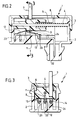
- FIGS. 4 and 5 show, similarly to FIGS. 2 and 3, sectional views of a modified embodiment of a small switch 40, which corresponds in its basic construction and function to the small switch 10 described with reference to FIGS. 1 to 3.
- a modified embodiment of a small switch 40 which corresponds in its basic construction and function to the small switch 10 described with reference to FIGS. 1 to 3.
- Mutually identical or corresponding parts are each provided with the same reference numerals in FIGS. 1 to 3 or 4 and 5.
- the only difference between the two small switches 10 and 40 is the design of the profile parts acting as stationary second contact elements, which in the Small switches 10 according to FIGS. 1 to 3 are designed as profile wires 22, 23, 24, but in the embodiment according to FIGS. 4, 5 they have the shape of profile plates 42, 43 and 44. With the surfaces of these profiled sheets correspondingly differently graded essentially at right angles, the contact tongues 12, 13 and 14 functioning as first contact elements interact. The mode of operation of the small switch 40 thus corresponds exactly to that of the small switch 10.
- the profile sheets 42, 43, 44 e.g. are particularly easy to manufacture as stamped parts or die-cast parts (in particular made of zinc alloy) and can also be attached to the housing (housing part 2) of the small switch 40 in the simplest manner.
- the profiled sheets 42, 43, 44 are inserted into correspondingly shaped slots in the lower housing part 2, after which the ends are pried open in a manner known per se, so that splayed ends 45, 46 are formed, through which the profiled sheets 42, 43, 44 on Are held.
- the profiled sheets 43, 43, 44 run in one piece into plug connections 52, which correspond to the plug connections 32, 33, 34 (FIG. 1) of the small switch 1.
- the profiled sheets 42, 43, 44 are fastened by caulking in the housing part 2. This is indicated in Fig. 4, in which a caulking tool 55 is shown in dash-dotted lines, with which a spread 56 can be produced on a shoulder in the region of the plug connection 52, through which the profile sheet 43 in question is also firmly anchored in the housing part 2 in the region of the plug connection 52 is.
Landscapes
- Push-Button Switches (AREA)
- Details Of Connecting Devices For Male And Female Coupling (AREA)
- Slide Switches (AREA)
Abstract
Description
- Die Erfindung betrifft einen elektrischen Kleinschalter zum Einbau in ein Schloß, insbesondere Heckklappenschloß eines Kraftfahrzeuges, mit einem Schaltergehäuse, mit einem Betätigungsglied, an dem ein beweglicher Teil des Schlosses angreift, mit vom Betätigungsglied bewegten ersten Kontaktelementen, mit stationär im Schaltergehäuse angeordneten zweiten Kontaktelementen, die durch Bewegung des ersten Kontaktelementes wahlweise miteinander elektrisch leitend verbindbar sind, und mit Steckanschlüssen zu den stationären zweiten Kontaktelementen.
- Elektrische Kleinschalter dieser Art müssen in ihrem Raum-bedarf so beschränkt ausgebildet werden, daß sie noch in ein Schloß, insbesondere das Heckklappenschloß eines Kraftfahrzeuges eingebaut werden können. Im letzteren Fall soll der Schalter in der Regel beim Öffnen des Schlosses eine Beleuchtung des Heckraumes (Kofferraum) und/oder eine Diebstahlsicherung auslösen. Es ist schwierig, diese Funktionen gleichzeitig platzsparend, funktionssicher und mit möglichst geringem Fertigungsaufwand in einem Kleinschalter unterzubringen.
- Der Erfindung liegt die Aufgabe zugrunde, einen gattungsgemäßen elektrischen Kleinschalter so zu verbessern, daß die Schaltfunktionen im Schalter platzsparend und betriebssicher untergebracht werden können und der Schalter mit äußerst geringem Aufwand herstellbar ist.
- Die Aufgabe wird erfindungsgemäß dadurch gelöst, daß das Betätigungsglied ein im Schaltergehäuse verschieblicher Schlitten ist, von dem als erste Kontaktelemente wenigstens zwei federnde Kontaktzungen abgehen, daß die stationären zweiten Kontaktelemente aus Profilteilen bestehen, die einstückig in die Steckanschlüsse übergehen, und daß die Profilteile zur Erzielung unterschiedlicher Kontaktzeitpunkte entsprechend unterschiedlich winkelig gebogene Oberflächen haben, an denen die Kontaktzungen angreifen.
- Die nachstehende Beschreibung einer bevorzugten Ausführungsform dient im Zusammenhang mit beiliegender Zeichnung der weiteren Erläuterung. Es zeigen:
- Fig. 1
- schaubildlich eine auseinandergezogene Darstellung eines elektrischen Kleinschalters;
- Fig. 2
- eine Schnittansicht entlang der Linie 2-2 in Figur 1;
- Fig. 3
- eine Schnittansicht entlang der Linie 3-3 in Figur 1;
- Fig. 4
- eine Schnittansicht ähnlich Fig. 2 einer anderen Ausführungsform und
- Fig. 5
- eine Schnittansicht entlang der Linie 5-5 in Fig. 4.
- Wie aus der Zeichnung ersichtlich, umfaßt ein elektrischer Kleinschalter 1 ein aus zwei voneinander ablösbaren Gehäuseteilen 2, 3 bestehendes Schaltergehäuse. Im Gehäuse (Gehäuseteil 2) ist auf einer Stange 4, von einer Schraubenfeder 5 vorgespannt, als Betätigungsglied ein Schlitten 6 verschieblich gelagert. Der Schlitten 6 ist durch die Schraubenfeder 5 in Figur 1 und 2 nach links vorgespannt. Vom Schlitten 6 steht ein Stift 7 durch einen Schlitz 8 im Gehäuseteil 3 nach außen ab. Am Stift 7 greift ein (nicht dargestellter) Teil eines Schlosses an, in welches der Schalter 1 eingebaut ist. Im Schließzustand des Schlosses wird der Schlitten 6 über den Stift 7 gegen die Wirkung der Feder 5 in seiner in Figur 1 und 2 rechts gelegenen Ausgangsposition gehalten. Beim Öffnen des Schlosses drückt die Feder 5 den Schlitten 6 aus seiner Ausgangsposition in die in Figur 1 und 2 dargestellte Endlage. Prinzipiell könnte die Feder 5 auch entfallen, wenn der Schlitten 6 durch die Öffnungs- und Schließbewegung eines Schlüssels zwangsläufig mitgenommen wird.
- Mit dem Schlitten 6 ist eine Kontaktplatte 9 durch eine Niet 11 fest verbunden. Von der Kontaktplatte 9 stehen als erste Kontaktelemente drei untereinander elektrisch leitend verbundene, federnde Kontaktzungen 12, 13 und 14 ab, die gemeinsam mit dem Schieber 6 bewegt werden.
- Im Gehäuseteil 2, der ebenso wie der Gehäuseteil 3 aus elektrisch isolierendem Kunststoff gefertigt ist, sind als stationäre zweite Kontaktelemente Profilteile in Gestalt von Profildrähten 22, 23, 24 fest eingelassen, die, wie insbesondere aus Figur 1 ersichtlich, zur Erzielung unterschiedlicher Kontaktpunkte entsprechend unterschiedlich rechtwinkelig abgebogen sind, so daß an ihrer Oberseite entsprechend abgebogene Kontaktoberflächen für die Kontaktzungen 12, 13, 14 entstehen. Die Profildrähte 22, 23, 24 haben bei der dargestellten Ausführungsform einen rechtwinkeligen Querschnitt, es können jedoch auch andere Querschnittsformen zum Einsatz kommen.
- Die jeweils am weitesten (in der Zeichnung nach oben) herausragenden, abgebogenen Bereiche 25, 26, 27 der aus elektrisch leitendem Werkstoff gefertigten Profildrähte 22, 23, 24 können bei entsprechender Stellung des Schlittens 7 mit den freien Enden der federnden Kontaktzungen 12, 13 bzw. 14 in elektrisch leitende Verbindung gelangen.
- Die in Figur 1 und 2 rechts gelegenen Enden der Profildrähte 22, 23, 24 gehen einstückig und ohne Änderung des Profilquerschnittes in Steckanschlüsse 30, 33 bzw. 34 über, mit denen über entsprechende Buchsen elektrische Anschlußleitungen verbunden werden können. Die abgebogenen Profildrähte 22, 23 und 24 mit ihren einstückig angebrachten Steckanschlüssen 32, 33, 34 lassen sich außerordentlich leicht herstellen und platzsparend in den Gehäuseteil 2 fest einfügen.
- Der beschriebene Kleinschalter 1 funktioniert in folgender Weise: Im Schließzustand des Schlosses befinden sich der Schieber 6 und die mit den Kontaktzungen 12, 13, 14 bestückte Kontaktplatte 9 in ihrer in Figur 1 und 2 rechts gelegenen Ausgangsstellung, in welcher die Schraubenfeder 5 gespannt ist. In dieser Stellung liegt die Kontaktzunge 12 am Bereich 25 des Profildrahtes 22 an, der ein Null- oder Masseleiter ist. Die Kontaktzungen 13, 14 machen aufgrund der entsprechend kurz ausgebildeten Bereiche 26, 27 der Profildrähte 23, 24 keinen Kontakt mit diesen Profildrähten, sie stehen vielmehr frei in das Gehäuse ab. Beim Öffnen des Schlosses verschieben sich die Kontaktzungen 12, 13, 14 in Figur 1 und 2 nach links. Dabei gelangt wegen der räumlichen Anordnung der abgebogenen Bereiche 26 und 27 zunächst die Kontaktzunge 14 mit dem Bereich 27 des Profildrahtes 24 in elektrisch leitende Verbindung, so daß zwischen den Profildrähten 22, 24 ein Stromkreis, der beispielsweise einer Diebstahlsicherung dient, geschlossen ist. Bei weiterer Verschiebung des Schiebers 6 in Figur 1 und 2 nach links gelangt kurz danach die Kontaktzunge 13 in elektrisch leitende Verbindung mit dem herausgebogenen Bereich 26 des Profildrahtes 23, so daß ein Stromkreis, der beispielsweise eine Lichtquelle in Betrieb setzt, zwischen dem Profildraht 23 und dem Profildraht 22 geschlossen ist.
- Auf diese Weise ist es möglich, rasch hintereinander eine Diebstahlsicherung und eine Beleuchtung zu gewährleisten. Bei entsprechender Abwinkelung der Profildrähte 23 und 24 lassen sich die Schaltzeitpunkte entsprechend verschieben. Beispielsweise ist auch eine gleichzeitige Einschaltung der Diebstahlsicherung und der Beleuchtung möglich. Die Kontaktzunge 12 verbleibt in ständigem Kontakt mit dem Bereich 25 des Profildrahtes 22.
- Wird das Schloß wieder geschlossen und hierdurch der Schieber 6 in Figur 1 und 2 nach rechts bewegt, so lösen sich die Kontaktzungen 13, 14 wiederum von den Profildrähten 23, 24, und die entsprechenden Stromkreise sind unterbrochen.
- Bei der dargestellten Ausführungsform sind zwei separate Stromkreise, z.B. für Beleuchtung und Diebstahlsicherung entsprechend den Profildrähten 23, 24 vorgesehen, die einen gemeinsamen Leiter in Gestalt des Profildrahtes 22 haben. Der als Null- oder Masseleiter dienende Profildraht 22 und die ihm zugeordnete Kontaktzunge 12 können auch entfallen, wenn die Kontaktzungen 13, 14 in anderer Weise ständig an Masse oder einen Nullpol angeschlossen sind. Auch ist es selbstverständlich möglich, mit dem beschriebenen Schalter nur einen einzigen Stromkreis zu schalten, beispielsweise über den Profildraht 23. In diesem Falle kann der Profildraht 24 und gegebenenfalls auch der Profildraht 22 entfallen.
- Entscheidend ist, daß der beschriebene elektrische Kleinschalter 1 außerordentliche klein baut, beispielsweise ein Volumen von nur 1 x 2 x 2,5 cm hat und bei hoher Robustheit und Betriebssicherheit relativ einfach und preiswert herstellbar ist.
- Die Figuren 4 und 5 zeigen ähnlich Fig. 2 und 3 Schnittansichten einer abgewandelten Ausführungsform eines Kleinschalters 40, der in seiner grundsätzlichen Konstruktion und Funktion dem anhand von Fig. 1 bis 3 beschriebenen Kleinschalter 10 entspricht. Einander gleiche oder entsprechende Teile sind in Fig. 1 bis 3 bzw. 4 und 5 jeweils mit den gleichen Bezugszeichen versehen.
- Der einzige Unterschied zwischen den beiden Kleinschaltern 10 und 40 besteht in der Ausbildung der als stationäre zweite Kontaktelemente wirkenden Profilteile, die bei dem Kleinschalter 10 gemäß Fig. 1 bis 3 als Profildrähte 22, 23, 24 ausgebildet sind, bei der Ausführungsform nach Fig. 4, 5 jedoch die Gestalt von Profilblechen 42, 43 und 44 haben. Mit den entsprechend unterschiedlich im wesentlichen rechtwinklig abgestuften Oberflächen dieser Profilbleche wirken die als erste Kontaktelemente funktionieren-den Kontaktzungen 12, 13 und 14 zusammen. Damit entspricht die Funktionsweise des Kleinschalters 40 genau derjenigen des Kleinschalters 10.
- Es wurde gefunden, daß die Profilbleche 42, 43, 44 z.B. als Stanzteile oder Druckgußteile (insbesondere aus Zinklegierung) besonders einfach herstellbar sind und im übrigen in einfachster Weise am Gehäuse (Gehäuseteil 2) des Kleinschalters 40 befestigt werden können. Hierzu werden die Profilbleche 42, 43, 44 in entsprechend geformte Schlitze in das untere Gehäuseteil 2 eingesteckt, wonach die Enden in an sich bekannter Weise aufgestemmt werden, so daß abgespreizte Enden 45, 46 entstehen, durch welche die Profilbleche 42, 43, 44 am Platz gehalten sind.
- An ihrer einen Seite laufen die Profilbleche 43, 43, 44 einstückig in Steckanschlüsse 52 aus, die den Steckananschlüssen 32, 33, 34 (Fig. 1) des Kleinschalters 1 entsprechen. Auch im Bereich dieser Steckanschlüsse werden die Profilbleche 42, 43, 44 durch Verstemmen im Gehäuseteil 2 befestigt. Dies ist in Fig. 4 angedeutet, in welcher ein Verstemmwerkzeug 55 strichpunktiert dargestellt ist, mit dem an einer Schulter im Bereich des Steckanschlusses 52 eine Aufspreizung 56 herstellbar ist, durch welche das betreffende Profilblech 43 auch im Bereich des Steckanschlusses 52 fest im Gehäuseteil 2 verankert ist.
Claims (7)
- Elektrischer Kleinschalter zum Einbau in ein Schloß, insbesondere Heckklappenschloß eines Kraftfahrzeuges, mit einem Schaltergehäuse, mit einem Betätigungsglied, an dem ein beweglicher Teil des Schlosses angreift, mit vom Betätigungsglied bewegten ersten Kontaktelementen, mit stationär im Schaltergehäuse angeordneten zweiten Kontaktelementen, die durch Bewegung der ersten Kontaktelemente wahlweise miteinander elektrisch leitend verbindbar sind, und mit Steckanschlüssen an den stationären zweiten Kontaktelementen,
dadurch gekennzeichnet,
daß das Betätigungsglied ein im Schaltergehäuse (2, 3) verschieblicher Schlitten (6) ist, von dem als erste Kontaktelemente wenigstens zwei federnde Kontaktzungen (12, 13) abgehen, daß die stationären zweiten Kontaktelemente aus Profilteilen (22, 23, 24; 42, 43, 44) bestehen, die einstückig in die Steckanschlüsse (32, 33, 34; 52) übergehen, und daß die Profilteile (22, 23, 24; 42, 43, 44) zur Erzielung unterschiedlicher Kontaktzeitpunkte entsprechend unterschiedlich winkelig gebogene Oberflächen haben, an denen die Kontaktzungen (12, 13) angreifen. - Schalter nach Anspruch 1, dadurch gekennzeichnet, daß die Profilteile als Profilbleche (42, 43, 44) ausgebildet sind.
- Schalter nach Anspruch 1, dadurch gekennzeichnet, daß die Profilteile als Profildrähte (22, 23, 24) ausgebildet sind.
- Schalter nach Anspruch 3, dadurch gekennzeichnet, daß die Profildrähte (22, 23, 24) einschließlich der Steckanschlüsse (32, 33, 34) überall gleichen Profilquerschnitt haben.
- Schalter nach Anspruch 3, dadurch gekennzeichnet, daß die Profildrähte (22, 23, 24) rechtwinkeligen Querschnitt haben.
- Schalter nach Anspruch 1, dadurch gekennzeichnet, daß drei Profilteile (22, 23, 24; 42, 43, 44) mit unterschiedlich gebogenen Oberflächen vorgesehen sind, die je mit einer federnden Kontaktzunge (12, 13, 14) zusammenwirken, wobei zwei Profilteile (23, 24; 43, 44) zwei getrennten Stromkreise zugeordnet sind, und das dritte Profilteil (22; 42) einen den beiden Stromkreisen gemeinsamen Leiter bildet.
- Schalter nach Anspruch 1, dadurch gekennzeichnet, daß der Schlitten (6) durch eine Feder (5) vorgespannt ist.
Applications Claiming Priority (4)
| Application Number | Priority Date | Filing Date | Title |
|---|---|---|---|
| DE4413495 | 1994-04-19 | ||
| DE4413495 | 1994-04-19 | ||
| DE4440902A DE4440902C2 (de) | 1994-04-19 | 1994-11-17 | Elektrischer Kleinschalter |
| DE4440902 | 1994-11-17 |
Publications (2)
| Publication Number | Publication Date |
|---|---|
| EP0678883A1 true EP0678883A1 (de) | 1995-10-25 |
| EP0678883B1 EP0678883B1 (de) | 1998-02-04 |
Family
ID=25935751
Family Applications (1)
| Application Number | Title | Priority Date | Filing Date |
|---|---|---|---|
| EP19950104990 Expired - Lifetime EP0678883B1 (de) | 1994-04-19 | 1995-04-04 | Elektrischer Kleinschalter |
Country Status (2)
| Country | Link |
|---|---|
| EP (1) | EP0678883B1 (de) |
| ES (1) | ES2113134T3 (de) |
Cited By (3)
| Publication number | Priority date | Publication date | Assignee | Title |
|---|---|---|---|---|
| EP0901138A2 (de) * | 1997-09-02 | 1999-03-10 | Toyodenso Kabushiki Kaisha | Schiebeschalter |
| WO2013171005A3 (de) * | 2012-05-15 | 2014-10-30 | Zf Friedrichshafen Ag | Mikroschalter mit mehrfachpositionserkennung für ein schliesssystem für ein fahrzeug sowie ein verfahren zur herstellung eines mikroschalters mit mehrfachpositionserkennung |
| CN108885955A (zh) * | 2016-03-30 | 2018-11-23 | 上海延锋金桥汽车饰件系统有限公司 | 用于控制台组件的机构 |
Citations (4)
| Publication number | Priority date | Publication date | Assignee | Title |
|---|---|---|---|---|
| US4185179A (en) * | 1977-02-05 | 1980-01-22 | Japan Aviation Electronics Industry, Ltd. | Key-switch device |
| US4185176A (en) * | 1977-02-18 | 1980-01-22 | Alps Electric Co., Ltd. | Change-over switch for use in high-frequency electric circuits |
| DE8317080U1 (de) * | 1983-03-28 | 1984-02-16 | Champion Spark Plug Italiana S.p.A., 10040 Druento, Torino | Lenkschloß mit Schalter, insbesondere für Kraftfahrzeuge |
| DE3610835A1 (de) * | 1986-04-01 | 1987-10-15 | Flach Klaus | Schalter zum ein-bzw. ausschalten von alarmeinrichtungen |
-
1995
- 1995-04-04 ES ES95104990T patent/ES2113134T3/es not_active Expired - Lifetime
- 1995-04-04 EP EP19950104990 patent/EP0678883B1/de not_active Expired - Lifetime
Patent Citations (4)
| Publication number | Priority date | Publication date | Assignee | Title |
|---|---|---|---|---|
| US4185179A (en) * | 1977-02-05 | 1980-01-22 | Japan Aviation Electronics Industry, Ltd. | Key-switch device |
| US4185176A (en) * | 1977-02-18 | 1980-01-22 | Alps Electric Co., Ltd. | Change-over switch for use in high-frequency electric circuits |
| DE8317080U1 (de) * | 1983-03-28 | 1984-02-16 | Champion Spark Plug Italiana S.p.A., 10040 Druento, Torino | Lenkschloß mit Schalter, insbesondere für Kraftfahrzeuge |
| DE3610835A1 (de) * | 1986-04-01 | 1987-10-15 | Flach Klaus | Schalter zum ein-bzw. ausschalten von alarmeinrichtungen |
Cited By (5)
| Publication number | Priority date | Publication date | Assignee | Title |
|---|---|---|---|---|
| EP0901138A2 (de) * | 1997-09-02 | 1999-03-10 | Toyodenso Kabushiki Kaisha | Schiebeschalter |
| EP0901138A3 (de) * | 1997-09-02 | 1999-09-08 | Toyodenso Kabushiki Kaisha | Schiebeschalter |
| WO2013171005A3 (de) * | 2012-05-15 | 2014-10-30 | Zf Friedrichshafen Ag | Mikroschalter mit mehrfachpositionserkennung für ein schliesssystem für ein fahrzeug sowie ein verfahren zur herstellung eines mikroschalters mit mehrfachpositionserkennung |
| CN108885955A (zh) * | 2016-03-30 | 2018-11-23 | 上海延锋金桥汽车饰件系统有限公司 | 用于控制台组件的机构 |
| CN108885955B (zh) * | 2016-03-30 | 2020-03-27 | 上海延锋金桥汽车饰件系统有限公司 | 用于控制台组件的机构 |
Also Published As
| Publication number | Publication date |
|---|---|
| EP0678883B1 (de) | 1998-02-04 |
| ES2113134T3 (es) | 1998-04-16 |
Similar Documents
| Publication | Publication Date | Title |
|---|---|---|
| DE4009279C2 (de) | ||
| DE3219579C2 (de) | ||
| DE202008005016U1 (de) | Kraftfahrzeugschloß | |
| EP1764813A1 (de) | Elektrischer Schalter | |
| DE3230414C3 (de) | ||
| EP0739096B1 (de) | Elektrische Schalteinrichtung | |
| DE2901246C2 (de) | Elektrische Schaltvorrichtung | |
| DE4431274C2 (de) | Verfahren zum Herstellen eines Elektro-Installationsgerätes sowie Elektro-Installationsgerät | |
| DE1465705B1 (de) | Elektrischer Schnappschalter mit Drueckerhebel | |
| WO1999054897A1 (de) | Schaltgerät mit einer schaltkammer-baugruppe | |
| DE3219294C2 (de) | ||
| DE4229756A1 (de) | Elektrisches Schaltgerät | |
| EP0678883B1 (de) | Elektrischer Kleinschalter | |
| WO2012072809A1 (de) | Elektrisches schaltelement des smd-typs | |
| DE2541922B2 (de) | Verriegelbarer Drucktastenschalter | |
| DE2741219C3 (de) | Schaltervorrichtung | |
| EP0817226A2 (de) | Wipptaster | |
| EP0388823B1 (de) | Sperrvorrichtung gegen gleichzeitiges Einschalten zweier mechanisch oder elektromagnetisch betätigter Schaltorgane | |
| DE3033808A1 (de) | Tastschalter | |
| EP1040499B1 (de) | Kopplungseinrichtung | |
| DE4440902C2 (de) | Elektrischer Kleinschalter | |
| DE2618572C3 (de) | Schiebetastenschalter | |
| DE3620105C1 (en) | Electrical contact switch | |
| EP1501108B1 (de) | Elektrischer Mehrwegeschalter | |
| DE3940285C2 (de) |
Legal Events
| Date | Code | Title | Description |
|---|---|---|---|
| PUAI | Public reference made under article 153(3) epc to a published international application that has entered the european phase |
Free format text: ORIGINAL CODE: 0009012 |
|
| AK | Designated contracting states |
Kind code of ref document: A1 Designated state(s): ES FR IT |
|
| 17P | Request for examination filed |
Effective date: 19960221 |
|
| GRAG | Despatch of communication of intention to grant |
Free format text: ORIGINAL CODE: EPIDOS AGRA |
|
| 17Q | First examination report despatched |
Effective date: 19970415 |
|
| GRAG | Despatch of communication of intention to grant |
Free format text: ORIGINAL CODE: EPIDOS AGRA |
|
| GRAH | Despatch of communication of intention to grant a patent |
Free format text: ORIGINAL CODE: EPIDOS IGRA |
|
| GRAH | Despatch of communication of intention to grant a patent |
Free format text: ORIGINAL CODE: EPIDOS IGRA |
|
| GRAA | (expected) grant |
Free format text: ORIGINAL CODE: 0009210 |
|
| AK | Designated contracting states |
Kind code of ref document: B1 Designated state(s): ES FR IT |
|
| ITF | It: translation for a ep patent filed | ||
| RAP4 | Party data changed (patent owner data changed or rights of a patent transferred) |
Owner name: HELAG-ELECTRONIC GMBH ELEKTROMECHANISCHE BAUELEMEN |
|
| REG | Reference to a national code |
Ref country code: ES Ref legal event code: FG2A Ref document number: 2113134 Country of ref document: ES Kind code of ref document: T3 |
|
| ET | Fr: translation filed | ||
| PLBE | No opposition filed within time limit |
Free format text: ORIGINAL CODE: 0009261 |
|
| STAA | Information on the status of an ep patent application or granted ep patent |
Free format text: STATUS: NO OPPOSITION FILED WITHIN TIME LIMIT |
|
| 26N | No opposition filed | ||
| PGFP | Annual fee paid to national office [announced via postgrant information from national office to epo] |
Ref country code: FR Payment date: 20030129 Year of fee payment: 9 |
|
| PG25 | Lapsed in a contracting state [announced via postgrant information from national office to epo] |
Ref country code: FR Free format text: LAPSE BECAUSE OF NON-PAYMENT OF DUE FEES Effective date: 20041231 |
|
| REG | Reference to a national code |
Ref country code: FR Ref legal event code: ST |
|
| PG25 | Lapsed in a contracting state [announced via postgrant information from national office to epo] |
Ref country code: IT Free format text: LAPSE BECAUSE OF NON-PAYMENT OF DUE FEES;WARNING: LAPSES OF ITALIAN PATENTS WITH EFFECTIVE DATE BEFORE 2007 MAY HAVE OCCURRED AT ANY TIME BEFORE 2007. THE CORRECT EFFECTIVE DATE MAY BE DIFFERENT FROM THE ONE RECORDED. Effective date: 20050404 |
|
| PGFP | Annual fee paid to national office [announced via postgrant information from national office to epo] |
Ref country code: ES Payment date: 20090310 Year of fee payment: 15 |
|
| REG | Reference to a national code |
Ref country code: ES Ref legal event code: FD2A Effective date: 20110715 |
|
| PG25 | Lapsed in a contracting state [announced via postgrant information from national office to epo] |
Ref country code: ES Free format text: LAPSE BECAUSE OF NON-PAYMENT OF DUE FEES Effective date: 20110705 |
|
| PG25 | Lapsed in a contracting state [announced via postgrant information from national office to epo] |
Ref country code: ES Free format text: LAPSE BECAUSE OF NON-PAYMENT OF DUE FEES Effective date: 20100405 |