EP0671764A2 - Verfahren zur Herstellung einer supraleitenden Schaltung - Google Patents
Verfahren zur Herstellung einer supraleitenden Schaltung Download PDFInfo
- Publication number
- EP0671764A2 EP0671764A2 EP95108249A EP95108249A EP0671764A2 EP 0671764 A2 EP0671764 A2 EP 0671764A2 EP 95108249 A EP95108249 A EP 95108249A EP 95108249 A EP95108249 A EP 95108249A EP 0671764 A2 EP0671764 A2 EP 0671764A2
- Authority
- EP
- European Patent Office
- Prior art keywords
- thin film
- superconducting
- substrate
- oxide superconductor
- barrier layer
- Prior art date
- Legal status (The legal status is an assumption and is not a legal conclusion. Google has not performed a legal analysis and makes no representation as to the accuracy of the status listed.)
- Ceased
Links
- 238000000034 method Methods 0.000 title claims abstract description 43
- 239000010409 thin film Substances 0.000 claims abstract description 144
- 239000002887 superconductor Substances 0.000 claims abstract description 88
- 239000000758 substrate Substances 0.000 claims abstract description 62
- 230000004888 barrier function Effects 0.000 claims abstract description 32
- QVGXLLKOCUKJST-UHFFFAOYSA-N atomic oxygen Chemical compound [O] QVGXLLKOCUKJST-UHFFFAOYSA-N 0.000 claims abstract description 25
- 239000001301 oxygen Substances 0.000 claims abstract description 25
- 229910052760 oxygen Inorganic materials 0.000 claims abstract description 25
- 238000006392 deoxygenation reaction Methods 0.000 claims abstract description 18
- 239000013078 crystal Substances 0.000 claims abstract description 14
- 238000009413 insulation Methods 0.000 claims description 9
- 238000000151 deposition Methods 0.000 claims description 5
- 239000002184 metal Substances 0.000 claims description 3
- 229910052751 metal Inorganic materials 0.000 claims description 3
- 239000000919 ceramic Substances 0.000 claims description 2
- 238000004519 manufacturing process Methods 0.000 abstract description 5
- 239000000463 material Substances 0.000 abstract description 4
- 239000010410 layer Substances 0.000 description 55
- 238000004544 sputter deposition Methods 0.000 description 9
- 239000012212 insulator Substances 0.000 description 6
- XKRFYHLGVUSROY-UHFFFAOYSA-N Argon Chemical compound [Ar] XKRFYHLGVUSROY-UHFFFAOYSA-N 0.000 description 4
- XUIMIQQOPSSXEZ-UHFFFAOYSA-N Silicon Chemical compound [Si] XUIMIQQOPSSXEZ-UHFFFAOYSA-N 0.000 description 4
- 150000001875 compounds Chemical class 0.000 description 4
- 229920002120 photoresistant polymer Polymers 0.000 description 4
- 239000011241 protective layer Substances 0.000 description 4
- 229910052710 silicon Inorganic materials 0.000 description 4
- 239000010703 silicon Substances 0.000 description 4
- 229910009203 Y-Ba-Cu-O Inorganic materials 0.000 description 3
- 238000005229 chemical vapour deposition Methods 0.000 description 3
- 239000004020 conductor Substances 0.000 description 3
- 230000000694 effects Effects 0.000 description 3
- 239000007789 gas Substances 0.000 description 3
- 238000001020 plasma etching Methods 0.000 description 3
- IJGRMHOSHXDMSA-UHFFFAOYSA-N Atomic nitrogen Chemical compound N#N IJGRMHOSHXDMSA-UHFFFAOYSA-N 0.000 description 2
- 229910002480 Cu-O Inorganic materials 0.000 description 2
- VEXZGXHMUGYJMC-UHFFFAOYSA-N Hydrochloric acid Chemical compound Cl VEXZGXHMUGYJMC-UHFFFAOYSA-N 0.000 description 2
- NBIIXXVUZAFLBC-UHFFFAOYSA-N Phosphoric acid Chemical compound OP(O)(O)=O NBIIXXVUZAFLBC-UHFFFAOYSA-N 0.000 description 2
- 229910052786 argon Inorganic materials 0.000 description 2
- 238000009792 diffusion process Methods 0.000 description 2
- 238000001312 dry etching Methods 0.000 description 2
- 238000005530 etching Methods 0.000 description 2
- 230000008020 evaporation Effects 0.000 description 2
- 238000001704 evaporation Methods 0.000 description 2
- 238000010438 heat treatment Methods 0.000 description 2
- 239000011229 interlayer Substances 0.000 description 2
- 238000003801 milling Methods 0.000 description 2
- 230000000644 propagated effect Effects 0.000 description 2
- 229910015901 Bi-Sr-Ca-Cu-O Inorganic materials 0.000 description 1
- 241000238366 Cephalopoda Species 0.000 description 1
- 229910002370 SrTiO3 Inorganic materials 0.000 description 1
- 229910000147 aluminium phosphate Inorganic materials 0.000 description 1
- 229910002113 barium titanate Inorganic materials 0.000 description 1
- 230000006866 deterioration Effects 0.000 description 1
- 238000002050 diffraction method Methods 0.000 description 1
- 239000007788 liquid Substances 0.000 description 1
- 238000003754 machining Methods 0.000 description 1
- 229910052757 nitrogen Inorganic materials 0.000 description 1
- 238000000059 patterning Methods 0.000 description 1
- 238000005240 physical vapour deposition Methods 0.000 description 1
- 239000000843 powder Substances 0.000 description 1
- 239000004065 semiconductor Substances 0.000 description 1
- 239000002356 single layer Substances 0.000 description 1
- 238000005245 sintering Methods 0.000 description 1
- 238000000992 sputter etching Methods 0.000 description 1
- 238000001039 wet etching Methods 0.000 description 1
Images


Classifications
-
- H—ELECTRICITY
- H01—ELECTRIC ELEMENTS
- H01L—SEMICONDUCTOR DEVICES NOT COVERED BY CLASS H10
- H01L21/00—Processes or apparatus adapted for the manufacture or treatment of semiconductor or solid state devices or of parts thereof
- H01L21/70—Manufacture or treatment of devices consisting of a plurality of solid state components formed in or on a common substrate or of parts thereof; Manufacture of integrated circuit devices or of parts thereof
- H01L21/71—Manufacture of specific parts of devices defined in group H01L21/70
- H01L21/768—Applying interconnections to be used for carrying current between separate components within a device comprising conductors and dielectrics
- H01L21/76838—Applying interconnections to be used for carrying current between separate components within a device comprising conductors and dielectrics characterised by the formation and the after-treatment of the conductors
- H01L21/76886—Modifying permanently or temporarily the pattern or the conductivity of conductive members, e.g. formation of alloys, reduction of contact resistances
- H01L21/76891—Modifying permanently or temporarily the pattern or the conductivity of conductive members, e.g. formation of alloys, reduction of contact resistances by using superconducting materials
-
- H—ELECTRICITY
- H01—ELECTRIC ELEMENTS
- H01L—SEMICONDUCTOR DEVICES NOT COVERED BY CLASS H10
- H01L23/00—Details of semiconductor or other solid state devices
- H01L23/48—Arrangements for conducting electric current to or from the solid state body in operation, e.g. leads, terminal arrangements ; Selection of materials therefor
- H01L23/488—Arrangements for conducting electric current to or from the solid state body in operation, e.g. leads, terminal arrangements ; Selection of materials therefor consisting of soldered or bonded constructions
- H01L23/498—Leads, i.e. metallisations or lead-frames on insulating substrates, e.g. chip carriers
- H01L23/49866—Leads, i.e. metallisations or lead-frames on insulating substrates, e.g. chip carriers characterised by the materials
- H01L23/49888—Leads, i.e. metallisations or lead-frames on insulating substrates, e.g. chip carriers characterised by the materials the conductive materials containing superconducting material
-
- H—ELECTRICITY
- H01—ELECTRIC ELEMENTS
- H01L—SEMICONDUCTOR DEVICES NOT COVERED BY CLASS H10
- H01L23/00—Details of semiconductor or other solid state devices
- H01L23/52—Arrangements for conducting electric current within the device in operation from one component to another, i.e. interconnections, e.g. wires, lead frames
- H01L23/522—Arrangements for conducting electric current within the device in operation from one component to another, i.e. interconnections, e.g. wires, lead frames including external interconnections consisting of a multilayer structure of conductive and insulating layers inseparably formed on the semiconductor body
- H01L23/532—Arrangements for conducting electric current within the device in operation from one component to another, i.e. interconnections, e.g. wires, lead frames including external interconnections consisting of a multilayer structure of conductive and insulating layers inseparably formed on the semiconductor body characterised by the materials
- H01L23/53204—Conductive materials
- H01L23/53285—Conductive materials containing superconducting materials
-
- H—ELECTRICITY
- H10—SEMICONDUCTOR DEVICES; ELECTRIC SOLID-STATE DEVICES NOT OTHERWISE PROVIDED FOR
- H10N—ELECTRIC SOLID-STATE DEVICES NOT OTHERWISE PROVIDED FOR
- H10N60/00—Superconducting devices
- H10N60/01—Manufacture or treatment
- H10N60/0268—Manufacture or treatment of devices comprising copper oxide
- H10N60/0661—Processes performed after copper oxide formation, e.g. patterning
-
- H—ELECTRICITY
- H01—ELECTRIC ELEMENTS
- H01L—SEMICONDUCTOR DEVICES NOT COVERED BY CLASS H10
- H01L2924/00—Indexing scheme for arrangements or methods for connecting or disconnecting semiconductor or solid-state bodies as covered by H01L24/00
- H01L2924/0001—Technical content checked by a classifier
- H01L2924/0002—Not covered by any one of groups H01L24/00, H01L24/00 and H01L2224/00
-
- Y—GENERAL TAGGING OF NEW TECHNOLOGICAL DEVELOPMENTS; GENERAL TAGGING OF CROSS-SECTIONAL TECHNOLOGIES SPANNING OVER SEVERAL SECTIONS OF THE IPC; TECHNICAL SUBJECTS COVERED BY FORMER USPC CROSS-REFERENCE ART COLLECTIONS [XRACs] AND DIGESTS
- Y10—TECHNICAL SUBJECTS COVERED BY FORMER USPC
- Y10S—TECHNICAL SUBJECTS COVERED BY FORMER USPC CROSS-REFERENCE ART COLLECTIONS [XRACs] AND DIGESTS
- Y10S505/00—Superconductor technology: apparatus, material, process
- Y10S505/70—High TC, above 30 k, superconducting device, article, or structured stock
- Y10S505/701—Coated or thin film device, i.e. active or passive
- Y10S505/703—Microelectronic device with superconducting conduction line
Definitions
- the present invention relates to a process for fabricating a superconducting circuit, more particularly, to a process for fabricating a structure of patterned superconducting wiring lines each made of a thin film of oxide superconductor deposited on a substrate.
- oxide superconductors were obtained initially in a bulk form of sintered block by powder sintering technique, now it becomes possible to prepare their thin films of high quality by physical vapour deposition or chemical vapour deposition techniques.
- the thin films of oxide superconductor are expected to be used in a variety of applications including sensors, SQUID, superconducting devices such as superconducting transistors or the like.
- oxide superconductor means any high-Tc compound oxide which shows the critical temperature of above 30 K.
- An object of the present invention is to solve the problem and provide a novel structure of a superconducting circuit having patterned superconducting wiring lines each made of a thin film of oxide superconductor deposited on a substrate and a process for fabricating the same, so as to increase the freedom of circuit designing and to make the best use of oxide superconductor.
- the present invention provides a process for fabricating a superconducting circuit having patterned superconducting wiring lines each made of a thin film of oxide superconductors deposited on a substrate, the circuit being characterized in that each of the superconducting wiring lines consists of at least one portion of a thin film of an oxide superconductor deposited on a flat substrate, each portion having the c-axis thereof oriented in a particular direction with respect to a surface of the substrate, remaining portions of the thin film of the oxide superconductor having the c-axis oriented in a different direction from the portion, and all the portion and the remaining portions make a continuous planar surface.
- Such a superconducting circuit is the subject of European patent application No 91 402 931.9 from which the present application is divided.
- a-axis b-axis
- c-axis art crystal axes of a crystal, as are usually used in the crystallography and they are known and determined in crystalline oxide superconductors to which the present invention is applicable.
- Orientation of these axes is usually defined by the direction of the crystal axis with respect to a surface of the substrate.
- a-axis oriented thin film is a thin film whose a-axis is perpendicular to the surface of substrate.
- the superconducting circuit having superconducting wiring lines made by the process according to the present invention can be fabricated from any oxide superconductor including compound oxide superconductors such as Y-Ba-Cu-O system, Bi-Sr-Ca-Cu-O system and Tl-Ba-Ca-Cu-O system.
- the substrate on which the thin film of oxide superconductor is deposited is preferably a single crystalline substrate of oxide such as MgO, SrTiO3, CdNdAlO4 or the like.
- the substrate may be a semiconductor substrate such as silicon substrate having or not having an insulator layer or buffer layer.
- the portion can be made of a thin film of the oxide superconductor whose a-axis is oriented perpendicular to the surface of the substrate.
- another upper thin film of oxide superconductor is further deposited on a surface of the planar surface through an insulation layer which can have a thickness of less than 10 nm.
- the thin film of oxide superconductor can have viaholes connecting vertically adjacent superconducting layers.
- the process according to the present invention for fabricating the superconducting circuit is characterized by the steps of depositing a thin film of an oxide superconductor whole over a surface of the substrate in such a condition that the a-axis of crystals of the thin film orients perpendicularly to the surface of the substrate, forming an oxygen barrier layer through which oxygen can't pass in a desired pattern on a surface of the thin film, subjecting thin film having oxygen barrier layer thereon to deoxygenation treatment to such an extent that exposed portions of thin film change to no superconductor, and removing the oxygen barrier layer from a surface of thin film to obtain a planar surface having patterned wiring lines at unexposed portions.
- the deoxygenation treatment can be carried out in a ultra-high vacuum chamber while the substrate is heated.
- the oxygen barrier layer can be made of ceramic such as MgO and SiN or metal such as Au.
- An essence of the process according to the present invention resides in that a thin film of oxide superconductor deposited whole over a surface of a substrate is exposed to deoxygenation treatment after the thin film of oxide superconductor is protected at predetermined areas by a patterned oxygen barrier layer.
- the thin film of oxide superconductor itself is directly machined by etching technique, so that the resulting superconducting patterned wiring lines doesn't have a planar surface. Still more, it is difficult to flatten a surface of the resulting superconducting patterned wiring lines.
- a patterned oxygen barrier layer is firstly formed on a surface of a thin film of oxide superconductor deposited on a surface of a substrate, and then deoxygenation treatment is effected on the thin film of oxide superconductor so as to produce a patterned superconducting wiring lines at the patterned area protected by the oxygen barrier layer. Since the patterned wiring lines according to the present invention are not subjected to physical machining, the resulting patterned wiring lines maintain a flat surface of the thin film as deposited, resulting in facilitating operations which will be effected in next stage for depositing another layer and/or for fabricating the other circuit elements on the resulting superconducting patterned wiring lines.
- the present inventors found such a fact that the diffusion velocity of oxygen depend on the crystal orientation of the thin film. In fact, oxygen escape slowly out of a c-axis oriented thin film of oxide superconductor, while the diffusion velocity of oxygen out of an a-axis oriented thin film of oxide superconductor is very rapid.
- the a-axis oriented thin film of oxide superconductor is advantageously used in the process according to the present invention in order to accelerate the deoxygenation treatment and to realize fine patterning.
- the portions above-mentioned can be divided into two groups of thin films of a-axis (or b-axis) oriented thin film and c-axis oriented thin film. It should be noted that there is no difference from the view point of flowability of superconducting current between the a-axis oriented thin film and the b-axis oriented thin film in the oxide superconductors to which the present invention is applicable, because the oxide superconductors have layered structures in which the superconducting current flow dominantly to the direction which is perpendicular to the c-axis.
- the process of the present invention may also be used in fabrication of a superconducting circuit characterized in that the superconducting wiring lines consist of first superconducting wiring lines and second superconducting wiring lines, all of the superconducting wiring lines being made of an identical oxide superconductor, each of first superconducting wiring lines is made of a thin film of oxide superconductor whose c-axis is perpendicular to a surface of the substrate so that a superconducting current flows in parallel with the surface of the substrate, each of second superconducting wiring lines is made of a thin film of oxide superconductor whose a-axis is perpendicular to the surface of the substrate so that a superconducting current flows vertically with respect to surface of the substrate, and the superconducting circuit has a planar surface.
- the superconducting circuit can have insulation zones, viaholes, another upper thin film of oxide superconductor deposited on the planar surface through an insulation layer which can have a thickness of less than 10 nm.
- This superconducting circuit can be produced by the steps of depositing a first thin film of an oxide superconductor whose a-axis or c-axis is oriented perpendicularly to a surface of substrate, removing predetermined areas of the first thin film to leave patterned first superconducting wiring lines, depositing a second thin film of the same oxide superconductor as the first thin film in such a condition that the second thin film becomes a c-axis oriented thin film or a-axis oriented thin film but has a different orientation from the first thin film on a whole surface of the substrate having the patterned first thin film, and removing an upper part of the second thin film so as to expose the patterned first thin film up to a planar level.
- the first thin film of oxide superconductor is preferably a c-axis oriented thin film and the second thin film of oxide superconductor is preferably an a-axis oriented thin film.
- the thin film of oxide superconductor shows anisotropy in the current property due to the anisotropy in crystal.
- the superconducting current flows dominantly along a direction which is perpendicular to the c-axis but almost zero current flow along a direction of the c-axis.
- This superconducting circuit has such a novel structure that both of the a-axis oriented thin film and the c-axis oriented thin film are juxtaposed in a layer and two superconducting wiring lines make a planar surface. However, substantially no current flow between these two superconducting lines even if these two thin films of a-axis oriented thin film and c-axis oriented thin film are juxtaposed because no substantial current is propagated between these two thin films.
- This novel structure of superconducting circuit permits to realize the mostly compacted wiring design due to such a fact that both of superconducting lines made of the a-axis oriented thin film and of the c-axis oriented thin film can be juxtaposed closely on a common surface of a substrate in the mostly compacted condition which could not be done in the case of metal conductors.
- the superconducting wiring lines made of a-axis oriented thin film are used to pass an electric current along a direction which is perpendicularly to the surface of the substrate, in other words, they function as conductor lines connecting two adjacent layers deposited one over another, while the superconducting wiring lines made of c-axis oriented thin film are used to pass an electric current along a direction which is in parallel with the surface of the substrate.
- This superconducting circuit can be used for fabricating a multi-layered superconducting circuit.
- superconducting wiring lines as well as viaholes can be arranged in a juxtaposition in each layer at the mostly compacted layout and can be contacted by vertical wiring lines filled in the viaholes.
- the superconducting circuit can be fabricated as following: At first, a first thin film of an oxide superconductor whose a-axis or c-axis is oriented perpendicularly to a surface of the substrate. Then, predetermined areas of the first thin film of oxide superconductor are removed to leave a patterned first superconducting lines. After then, a second thin film of the same oxide superconductor is deposited in such a condition that the second thin film becomes a different orientation from the first thin film thereon.
- the first thin film is an a-axis oriented thin film
- a c-axis oriented thin film is deposited and when the first thin film is a c-axis oriented thin film, an a-axis oriented thin film is deposited. It is preferable to prepare firstly the c-axis oriented thin film in consideration of such a fact that a higher substrate temperature is required to prepare the c-axis oriented thin film.
- the deoxygenation is effected on such portions of the superconducting lines that will not be used as wiring lines.
- the deoxygenation can be done to the second thin film so as to produce a finally patterned superconducting circuit.
- the process has following merits:
- the superconducting patterned wiring lines prepared by the present invention have a planar surface which facilitates fabrication of a superconducting devices and also possess high mechanical resistance, because all portions of thin film are connected to each other through the non-superconductor which is made of the same material as the superconducting lines. Still more, two different superconducting lines for passing superconducting current in parallel with a surface of a substrate and for passing superconducting current perpendicularly to the surface of the substrate can be arranged in juxtapositions in a layer. Still more, deterioration of superconducting properties of thin films of oxide superconductor caused by heat-treatment can be prevented, because all of superconducting lines each having a different function and the insulator zones can be produced by an identical material.
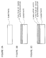
- Figure 1 is an illustrative perspective view of patterned superconducting wiring lines provided by the first aspect of the present invention.
- Figure 2A to 2H illustrate successive steps for fabricating the patterned superconducting wiring lines shown in Figure 1.
- Figure 3 is an illustrative perspective view of a superconducting circuit having patterned wiring lines provided by the second aspect of the present invention.
- FIG. 4A to 4F illustrate successive steps for fabricating the superconducting circuit shown in Figure 3.
- Figure 1 is an illustrative perspective view of superconducting wiring lines provided by the process of the present invention.
- the superconducting wiring line 2' consists of at least a portion of a crystalline thin film 2 made of oxide superconductor deposited on a substrate 1.
- the superconducting wiring line 2' is made of a portion of the thin film 2 whose an a-axis is oriented perpendicularly to a surface of said substrate 1.
- the superconducting wiring line 2' is surrounded by insulation zones 2'' consisting of the remaining portions of the crystalline thin film 2 in which oxygen is removed out of the crystals and hence they are changed to non-superconductor.
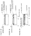
- FIG. 2A to 2H illustrate successive steps for fabricating the superconducting wiring pattern shown in Figure 1.
- a substrate 1 having a smooth surface is prepared (Fig. 2A).
- the substrate can be MgO (100) single crystal.
- Other substrate such as CdNdAlO4 substrate or a silicon substrate having a buffer layer can be used in place of the MgO single crystal.
- a thin film 2 of oxide superconductor having a thickness of more than 200 nm is deposited (Fig. 2B).
- This thin film 2 can be prepared by any technique including off-axis sputtering. reactive evaporation or the like.
- the thin film 2 of oxide superconductor is prepared by the off-axis sputtering technique under the presence of a mixed sputtering gas of Ar + O2 (volume ratio of 9 : 1) of 10 Pa.
- the substrate is heated at a temperature which is not higher than 650 °C so that the thin film of oxide superconductor deposited becomes an a-axis orientated thin film.
- the oxygen barrier layer 3 may be made of MgO, SiN, Au or the like.
- the oxygen barrier layer 3 is patterned by known photolithograph technique as is shown in Figure 2D.
- a pattern formed in the barrier layer 3 corresponds to the final superconducting wiring pattern.
- the resulting patterned barrier layer 3a has the same pattern as the superconducting wiring pattern.
- the thin film of oxide superconductor 2 having the resulting patterned barrier layer 3a thereon is subjected to deoxygenation treatment as is shown in Figure 2E.
- the deoxygenation is effected by maintaining the substrate having the thin film of oxide superconductor 2 and the patterned barrier layer 3a thereon in a ultra-high vacuum chamber for one hour while the substrate is heated at a temperature which is not higher than 400 °C.
- oxygen escape out of the thin film at the areas which are not covered with the barrier layer 3a to produce insulating zones or non-superconductor zone 2a in the thin film 2 while the areas covered with the barrier layer 3a are protected from the deoxygenation treatment to leave a patterned superconducting wiring lines.
- the resulting thin film having the patterned superconducting wiring lines can be utilized as they are as a superconducting circuit having conductor lines.
- an outer protective layer 4 is preferably formed on a surface of the thin film 2 of oxide superconductor as is shown in Figure 2F-1.
- a protective layer 4 is deposited whole over the surface of the thin film 2 having the oxygen barrier layer 3a as is shown in Figure 2F-2.
- the two layers of the protective layer 4 and the barrier layer 3a are etched back to leave a flat thin film layer 4' consisting of the protective layer 4 and the barrier layer 3a as is shown inf Figure 2G.
- a thickness of the flat thin film layer 4' must be reduced as thin as possible. This etching can be carried out by a reactive ion etching technique or ion milling technique.
- the flat thin film layer 4' can be used as an insulator layer which separates adjacent two thin films layers 2 and 5 of oxide superconductor or can be used an interlayer barrier which functions as a weak junction in a superconducting device utilizing the proximity effect. In the latter case, the thickness of the barrier layer 3a remained in the flat thin film layer 4' must be as thin as possible.
- the thickness of the barrier layer 3a remained is preferably reduced to less than 10 nm so that a tunnel effect is realized by the barrier layer 3a.
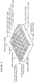
- Figure 3 is an illustrative perspective view of a further superconducting circuit which may be fabricated by a process incorporating the process of the present invention.
- the superconducting circuit of Figure 3 has a thin film layer 2 of oxide superconductor deposited on a substrate 1.
- the thin film layer 2 of oxide superconductor comprises c-axis oriented thin film zones 21, a-axis oriented thin film zones 22, insulation zones 23 in which superconductivity is lost and viaholes 24.
- the c-axis oriented thin film zones 21 provide superconducting lines in which superconducting current is propagated in parallel with a surface of the substrate 1.
- the a-axis oriented thin film zones 22 provide superconducting lines in which superconducting current flow perpendicularly to the surface of the substrate 1. No superconducting current flow in the insulation zones 23.
- the viaholes 24 are used to connect layers in a stacked multi-layered circuit (not shown).
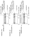
- Figure 4A to 4F illustrate successive steps for fabricating the superconducting circuit shown in Figure 3.
- the oxide superconductor used in this Example 4 is a compound oxide superconductor of Y-Ba-Cu-O system.
- the substrate 1 consists of a silicon base substrate 1a having a buffer layer 1b which is composed of an under-layer of MgAl2O3 having a thickness of 350 nm deposited by chemical vapour deposition (CVD) technique and an upper-layer of BaTiO3 having a thickness of 75 nm deposited by sputtering technique.
- MgO (100) substrate, CdNdAlO4 substrate or the like can be preferably used in place of the silicon substrate.
- a thin film 2 of oxide superconductor having a thickness of more than 200 nm as is shown in Figure 4B is deposited.
- This thin film 2 can be prepared by an off-axis sputtering technique, a reactive evaporation technique the like.
- the thin film 2 of oxide superconductor is prepared by the off-axis sputtering technique under the presence of a mixed sputtering gas of Ar + O2 (volume ratio of 9 : 1) of 10 Pa.
- the substrate is heated at a temperature above 700 °C so that the thin film of oxide superconductor deposited shows c-axis orientation.
- a photoresist layer 3 having a predetermined patter is coated on the thin film 2 of oxide superconductor obtained by a well-known technique.
- photoresist layer 3 After the photoresist layer 3 is cured, exposed areas which are not covered with the photoresist 3 are removed by a dry etching technique such as reactive ion etching and argon milling or by a wet etching technique such as treatment with phosphoric acid or hydrochloric acid, so as to produce a patterned superconducting lines 2c consisting of the c-axis oriented thin film as is shown in Figure 4D.
- a dry etching technique such as reactive ion etching and argon milling
- wet etching technique such as treatment with phosphoric acid or hydrochloric acid
- an a-axis oriented thin film 2a of the same oxide superconductor is deposited on the surface of the substrate 1 having the patterned superconducting lines 2c consisting of the c-axis oriented thin film.
- This thin film 2a of oxide superconductor also is prepared by the off-axis sputtering technique under the presence of a mixed sputtering gas of Ar + O2 (volume ratio of 9 : 1) of 10 Pa but the substrate is heated at a temperature which is not higher than 650 °C so that the thin film of oxide superconductor 2a deposited becomes an a-axis oriented thin film.
- a surface of the a-axis oriented thin film 2a is smoothed by a dry etching technique such as reactive ion etching or argon milling to obtain a superconducting circuit according to the present invention as is shown in Figure 4F in which both of the superconducting lines 2c made of c-axis oriented thin film and the superconducting lines 2a made of a-axis oriented thin film make a planar surface on a common plane or on the surface of the substrate 1.
- a dry etching technique such as reactive ion etching or argon milling
- an insulator layer may be deposited on a surface of the resulting superconducting circuit of Figure 3 before the circuit is passed to next stage for completing the superconducting circuit into a desired superconducting device.
- the insulation zones 23 shown in Figure 3 can be prepared according to the present invention by deoxygenation of the thin film 2 of oxide superconductor. Namely, after predetermined areas of the thin film 2 of oxide superconductor are protected with photoresist or insulator, remaining exposed areas are subjected to a treatment of deoxygenation so that the exposed areas are changed into non-superconductor.
Landscapes
- Engineering & Computer Science (AREA)
- Physics & Mathematics (AREA)
- Condensed Matter Physics & Semiconductors (AREA)
- General Physics & Mathematics (AREA)
- Computer Hardware Design (AREA)
- Microelectronics & Electronic Packaging (AREA)
- Power Engineering (AREA)
- Manufacturing & Machinery (AREA)
- Superconductor Devices And Manufacturing Methods Thereof (AREA)
- Internal Circuitry In Semiconductor Integrated Circuit Devices (AREA)
Applications Claiming Priority (5)
| Application Number | Priority Date | Filing Date | Title |
|---|---|---|---|
| JP2294294A JP2703403B2 (ja) | 1990-10-31 | 1990-10-31 | 超電導配線の作製方法 |
| JP2294295A JP2703404B2 (ja) | 1990-10-31 | 1990-10-31 | 超電導回路とその作製方法 |
| JP294295/90 | 1990-10-31 | ||
| JP294294/90 | 1990-10-31 | ||
| EP91402931A EP0484248B1 (de) | 1990-10-31 | 1991-10-31 | Supraleitende Schaltung und Verfahren zu ihrer Herstellung |
Related Parent Applications (1)
| Application Number | Title | Priority Date | Filing Date |
|---|---|---|---|
| EP91402931.9 Division | 1991-10-31 |
Publications (2)
| Publication Number | Publication Date |
|---|---|
| EP0671764A2 true EP0671764A2 (de) | 1995-09-13 |
| EP0671764A3 EP0671764A3 (de) | 1995-10-11 |
Family
ID=26559765
Family Applications (2)
| Application Number | Title | Priority Date | Filing Date |
|---|---|---|---|
| EP95108249A Ceased EP0671764A2 (de) | 1990-10-31 | 1991-10-31 | Verfahren zur Herstellung einer supraleitenden Schaltung |
| EP91402931A Expired - Lifetime EP0484248B1 (de) | 1990-10-31 | 1991-10-31 | Supraleitende Schaltung und Verfahren zu ihrer Herstellung |
Family Applications After (1)
| Application Number | Title | Priority Date | Filing Date |
|---|---|---|---|
| EP91402931A Expired - Lifetime EP0484248B1 (de) | 1990-10-31 | 1991-10-31 | Supraleitende Schaltung und Verfahren zu ihrer Herstellung |
Country Status (4)
| Country | Link |
|---|---|
| US (1) | US5672569A (de) |
| EP (2) | EP0671764A2 (de) |
| CA (2) | CA2054597C (de) |
| DE (1) | DE69124072T2 (de) |
Families Citing this family (9)
| Publication number | Priority date | Publication date | Assignee | Title |
|---|---|---|---|---|
| EP0973208B1 (de) * | 1992-07-28 | 2005-04-27 | Nippon Telegraph And Telephone Corporation | Vorrichtung mit Gitteranpassung und Verfahren zu ihrer Herstellung |
| JP2822953B2 (ja) * | 1995-09-14 | 1998-11-11 | 日本電気株式会社 | 超伝導回路の製造方法 |
| US6022832A (en) | 1997-09-23 | 2000-02-08 | American Superconductor Corporation | Low vacuum vapor process for producing superconductor articles with epitaxial layers |
| US6027564A (en) * | 1997-09-23 | 2000-02-22 | American Superconductor Corporation | Low vacuum vapor process for producing epitaxial layers |
| US6458223B1 (en) | 1997-10-01 | 2002-10-01 | American Superconductor Corporation | Alloy materials |
| US6428635B1 (en) | 1997-10-01 | 2002-08-06 | American Superconductor Corporation | Substrates for superconductors |
| US6475311B1 (en) | 1999-03-31 | 2002-11-05 | American Superconductor Corporation | Alloy materials |
| US10158061B2 (en) | 2013-11-12 | 2018-12-18 | Varian Semiconductor Equipment Associates, Inc | Integrated superconductor device and method of fabrication |
| US9947441B2 (en) * | 2013-11-12 | 2018-04-17 | Varian Semiconductor Equipment Associates, Inc. | Integrated superconductor device and method of fabrication |
Citations (1)
| Publication number | Priority date | Publication date | Assignee | Title |
|---|---|---|---|---|
| EP0358879A2 (de) * | 1988-09-13 | 1990-03-21 | Hewlett-Packard Company | Verfahren zur Herstellung hochintegrierter Verbindungen |
Family Cites Families (15)
| Publication number | Priority date | Publication date | Assignee | Title |
|---|---|---|---|---|
| DE3854238T2 (de) * | 1987-04-08 | 1996-03-21 | Hitachi Ltd | Verfahren zur Herstellung eines supraleitenden Elements. |
| JPS63314850A (ja) * | 1987-06-18 | 1988-12-22 | Fujitsu Ltd | 半導体装置 |
| US5183800A (en) * | 1987-07-15 | 1993-02-02 | Sharp Kabushiki Kaisha | Interconnection method for semiconductor device comprising a high-temperature superconductive material |
| JPH079905B2 (ja) * | 1987-07-15 | 1995-02-01 | シャープ株式会社 | 半導体装置の配線方法 |
| JPS6435971A (en) * | 1987-07-30 | 1989-02-07 | Mitsubishi Electric Corp | Superconductor device |
| DE3726016A1 (de) * | 1987-08-05 | 1989-02-16 | Siemens Ag | Verfahren zur herstellung eines schichtartigen aufbaus aus einem oxidkeramischen supralteitermaterial |
| US5079216A (en) * | 1987-09-04 | 1992-01-07 | Henty David L | Composite high temperature superconductor and substrate structure |
| JPS6469064A (en) * | 1987-09-10 | 1989-03-15 | Nec Corp | Manufacture of oxide superconducting wiring |
| JPH01171246A (ja) * | 1987-12-25 | 1989-07-06 | Mitsubishi Metal Corp | 超伝導体配線の形成方法 |
| CA1336567C (en) * | 1988-02-03 | 1995-08-08 | Franz Joseph Himpsel | Epitaxy of high t_ superconductors on silicon |
| EP0342039B1 (de) * | 1988-05-11 | 1994-08-31 | Canon Kabushiki Kaisha | Josephson-Einrichtung und Verfahren zu ihrer Herstellung |
| JPH0223674A (ja) * | 1988-07-12 | 1990-01-25 | Matsushita Electric Ind Co Ltd | 配線の接続方法 |
| JPH0355889A (ja) * | 1989-07-25 | 1991-03-11 | Furukawa Electric Co Ltd:The | 超電導多層回路の製造方法 |
| DE69119022T2 (de) * | 1990-10-08 | 1996-10-31 | Sumitomo Electric Industries | Supraleitende Einrichtung mit ultradünnem Kanal aus oxydisch supraleitendem Material und Verfahren zu deren Herstellung |
| JPH04321285A (ja) * | 1991-04-19 | 1992-11-11 | Sanyo Electric Co Ltd | 超電導電磁波検出素子及びその作製方法 |
-
1991
- 1991-10-31 EP EP95108249A patent/EP0671764A2/de not_active Ceased
- 1991-10-31 CA CA002054597A patent/CA2054597C/en not_active Expired - Fee Related
- 1991-10-31 EP EP91402931A patent/EP0484248B1/de not_active Expired - Lifetime
- 1991-10-31 CA CA002185936A patent/CA2185936A1/en not_active Abandoned
- 1991-10-31 DE DE69124072T patent/DE69124072T2/de not_active Expired - Fee Related
-
1995
- 1995-03-08 US US08/400,813 patent/US5672569A/en not_active Expired - Fee Related
Patent Citations (1)
| Publication number | Priority date | Publication date | Assignee | Title |
|---|---|---|---|---|
| EP0358879A2 (de) * | 1988-09-13 | 1990-03-21 | Hewlett-Packard Company | Verfahren zur Herstellung hochintegrierter Verbindungen |
Also Published As
| Publication number | Publication date |
|---|---|
| EP0484248A3 (en) | 1992-08-26 |
| EP0671764A3 (de) | 1995-10-11 |
| CA2054597C (en) | 1997-08-19 |
| DE69124072D1 (de) | 1997-02-20 |
| CA2054597A1 (en) | 1992-05-01 |
| CA2185936A1 (en) | 1992-05-01 |
| EP0484248B1 (de) | 1997-01-08 |
| US5672569A (en) | 1997-09-30 |
| DE69124072T2 (de) | 1997-08-07 |
| EP0484248A2 (de) | 1992-05-06 |
Similar Documents
| Publication | Publication Date | Title |
|---|---|---|
| US5811375A (en) | Superconducting multilayer interconnection formed of oxide superconductor material and method for manufacturing the same | |
| US5407903A (en) | Superconducting device having a reduced thickness of oxide superconducting layer | |
| US5750474A (en) | Method for manufacturing a superconductor-insulator-superconductor Josephson tunnel junction | |
| US5215960A (en) | Method for manufacturing oxide superconducting devices | |
| US5672569A (en) | Process for fabricating a superconducting circuit | |
| US5466664A (en) | Method for manufacturing a superconducting device having a thin superconducting channel formed of oxide superconductor material | |
| US5229360A (en) | Method for forming a multilayer superconducting circuit | |
| US6023072A (en) | Superconductor hetero-epitaxial josephson junction | |
| CA2047020C (en) | Substrate for superconducting device | |
| EP0546904B1 (de) | Verfahren zum Herstellen eines künstlichen Josephson-Korngrenzen-Übergangselementes | |
| US5422337A (en) | Step-edged grain boundary Josephson junction with 5 to 30 degrees inclined angle | |
| EP0427640A1 (de) | Tunnelübergangsanordnung mit supraleitendem Oxydverbundmaterial | |
| US5646096A (en) | Process for fabrication superconducting wiring lines | |
| US5714767A (en) | Method for manufacturing superconducting device having a reduced thickness of oxide superconducting layer and superconducting device manufactured thereby | |
| EP0534854B1 (de) | Supraleitende Dünnschicht aus oxidisch supraleitendem Material, supraleitender Strompfad und supraleitende Einrichtung mit der supraleitenden Dünnschicht | |
| US5462919A (en) | Method for manufacturing superconducting thin film formed of oxide superconductor having non superconducting region and device utilizing the superconducting thin film | |
| US5612290A (en) | Josephson junction device formed of oxide superconductor | |
| JPH05190921A (ja) | 超電導接合を有する素子およびその作製方法 | |
| JP3425422B2 (ja) | 超電導素子の製造方法 | |
| JPH01183138A (ja) | 半導体装置 | |
| JP3058515B2 (ja) | 超電導ジョセフソン素子およびその製法 | |
| JP2708673B2 (ja) | 超伝導薄膜縦型接合素子の製造方法 | |
| JP2663856B2 (ja) | エッジ型ジョセフソン接合を用いる超伝導回路およびその製造方法 | |
| JPH10209514A (ja) | 銅酸化物超伝導薄膜の製造方法 | |
| JPH06132573A (ja) | 酸化物超伝導薄膜およびトンネル接合型ジョセフソン素子 |
Legal Events
| Date | Code | Title | Description |
|---|---|---|---|
| PUAI | Public reference made under article 153(3) epc to a published international application that has entered the european phase |
Free format text: ORIGINAL CODE: 0009012 |
|
| PUAL | Search report despatched |
Free format text: ORIGINAL CODE: 0009013 |
|
| AC | Divisional application: reference to earlier application |
Ref document number: 484248 Country of ref document: EP |
|
| AK | Designated contracting states |
Kind code of ref document: A2 Designated state(s): DE FR GB |
|
| RHK1 | Main classification (correction) |
Ipc: H01L 21/90 |
|
| AK | Designated contracting states |
Kind code of ref document: A3 Designated state(s): DE FR GB |
|
| 17P | Request for examination filed |
Effective date: 19960403 |
|
| 17Q | First examination report despatched |
Effective date: 19961024 |
|
| GRAG | Despatch of communication of intention to grant |
Free format text: ORIGINAL CODE: EPIDOS AGRA |
|
| RHK1 | Main classification (correction) |
Ipc: H01L 21/90 |
|
| STAA | Information on the status of an ep patent application or granted ep patent |
Free format text: STATUS: THE APPLICATION HAS BEEN REFUSED |
|
| 18R | Application refused |
Effective date: 19981227 |