EP0669506B2 - Kondensator für eine Klimaanlage eines Fahrzeuges - Google Patents
Kondensator für eine Klimaanlage eines Fahrzeuges Download PDFInfo
- Publication number
- EP0669506B2 EP0669506B2 EP95100520A EP95100520A EP0669506B2 EP 0669506 B2 EP0669506 B2 EP 0669506B2 EP 95100520 A EP95100520 A EP 95100520A EP 95100520 A EP95100520 A EP 95100520A EP 0669506 B2 EP0669506 B2 EP 0669506B2
- Authority
- EP
- European Patent Office
- Prior art keywords
- collector
- collecting means
- gauze filter
- pipe
- condenser
- Prior art date
- Legal status (The legal status is an assumption and is not a legal conclusion. Google has not performed a legal analysis and makes no representation as to the accuracy of the status listed.)
- Expired - Lifetime
Links
Images
Classifications
-
- F—MECHANICAL ENGINEERING; LIGHTING; HEATING; WEAPONS; BLASTING
- F25—REFRIGERATION OR COOLING; COMBINED HEATING AND REFRIGERATION SYSTEMS; HEAT PUMP SYSTEMS; MANUFACTURE OR STORAGE OF ICE; LIQUEFACTION SOLIDIFICATION OF GASES
- F25B—REFRIGERATION MACHINES, PLANTS OR SYSTEMS; COMBINED HEATING AND REFRIGERATION SYSTEMS; HEAT PUMP SYSTEMS
- F25B39/00—Evaporators; Condensers
- F25B39/04—Condensers
-
- B—PERFORMING OPERATIONS; TRANSPORTING
- B60—VEHICLES IN GENERAL
- B60H—ARRANGEMENTS OF HEATING, COOLING, VENTILATING OR OTHER AIR-TREATING DEVICES SPECIALLY ADAPTED FOR PASSENGER OR GOODS SPACES OF VEHICLES
- B60H1/00—Heating, cooling or ventilating [HVAC] devices
- B60H1/32—Cooling devices
- B60H1/3204—Cooling devices using compression
- B60H1/3227—Cooling devices using compression characterised by the arrangement or the type of heat exchanger, e.g. condenser, evaporator
-
- B—PERFORMING OPERATIONS; TRANSPORTING
- B60—VEHICLES IN GENERAL
- B60H—ARRANGEMENTS OF HEATING, COOLING, VENTILATING OR OTHER AIR-TREATING DEVICES SPECIALLY ADAPTED FOR PASSENGER OR GOODS SPACES OF VEHICLES
- B60H1/00—Heating, cooling or ventilating [HVAC] devices
- B60H1/32—Cooling devices
- B60H1/3204—Cooling devices using compression
- B60H1/3229—Cooling devices using compression characterised by constructional features, e.g. housings, mountings, conversion systems
-
- F—MECHANICAL ENGINEERING; LIGHTING; HEATING; WEAPONS; BLASTING
- F25—REFRIGERATION OR COOLING; COMBINED HEATING AND REFRIGERATION SYSTEMS; HEAT PUMP SYSTEMS; MANUFACTURE OR STORAGE OF ICE; LIQUEFACTION SOLIDIFICATION OF GASES
- F25B—REFRIGERATION MACHINES, PLANTS OR SYSTEMS; COMBINED HEATING AND REFRIGERATION SYSTEMS; HEAT PUMP SYSTEMS
- F25B43/00—Arrangements for separating or purifying gases or liquids; Arrangements for vaporising the residuum of liquid refrigerant, e.g. by heat
- F25B43/003—Filters
-
- F—MECHANICAL ENGINEERING; LIGHTING; HEATING; WEAPONS; BLASTING
- F25—REFRIGERATION OR COOLING; COMBINED HEATING AND REFRIGERATION SYSTEMS; HEAT PUMP SYSTEMS; MANUFACTURE OR STORAGE OF ICE; LIQUEFACTION SOLIDIFICATION OF GASES
- F25B—REFRIGERATION MACHINES, PLANTS OR SYSTEMS; COMBINED HEATING AND REFRIGERATION SYSTEMS; HEAT PUMP SYSTEMS
- F25B2339/00—Details of evaporators; Details of condensers
- F25B2339/04—Details of condensers
- F25B2339/044—Condensers with an integrated receiver
- F25B2339/0441—Condensers with an integrated receiver containing a drier or a filter
-
- F—MECHANICAL ENGINEERING; LIGHTING; HEATING; WEAPONS; BLASTING
- F25—REFRIGERATION OR COOLING; COMBINED HEATING AND REFRIGERATION SYSTEMS; HEAT PUMP SYSTEMS; MANUFACTURE OR STORAGE OF ICE; LIQUEFACTION SOLIDIFICATION OF GASES
- F25B—REFRIGERATION MACHINES, PLANTS OR SYSTEMS; COMBINED HEATING AND REFRIGERATION SYSTEMS; HEAT PUMP SYSTEMS
- F25B2400/00—General features or devices for refrigeration machines, plants or systems, combined heating and refrigeration systems or heat-pump systems, i.e. not limited to a particular subgroup of F25B
- F25B2400/16—Receivers
- F25B2400/162—Receivers characterised by the plug or stop
-
- F—MECHANICAL ENGINEERING; LIGHTING; HEATING; WEAPONS; BLASTING
- F25—REFRIGERATION OR COOLING; COMBINED HEATING AND REFRIGERATION SYSTEMS; HEAT PUMP SYSTEMS; MANUFACTURE OR STORAGE OF ICE; LIQUEFACTION SOLIDIFICATION OF GASES
- F25B—REFRIGERATION MACHINES, PLANTS OR SYSTEMS; COMBINED HEATING AND REFRIGERATION SYSTEMS; HEAT PUMP SYSTEMS
- F25B40/00—Subcoolers, desuperheaters or superheaters
- F25B40/02—Subcoolers
Definitions
- the invention relates to a capacitor for a Air conditioning of a vehicle with a refrigerant flowed through tube-rib block, the both sides each provided with a manifold, wherein parallel to one of the manifolds a tubular Collector is arranged, with the associated manifold is in flow communication and a filter screen contains.
- the invention is based on the object, a Condenser of the type mentioned above, that the functionality due to a Maintenance is improved.
- the filter screen is easily accessible and exchangeable. It is possible by means of a simple Maintenance process the condition of the filter screen to review and if necessary to improve the Function of the air conditioning or to maintain to replace the function.
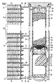
- Fig. 1 capacitor has a tube-rib block (10) from a Variety of flat tubes (11) and corrugated fins (12).
- the each outermost corrugated ribs (12) are by means of a final sheet (13) covered.
- the ends of the flat tubes (11) are in a grounded floor (14) inserted, which also for the ends of the flat tubes on the opposite side, not shown applies.
- the floors (14) are covered by covers Hoppers (15) closed by End walls (16, 17) and partitions (18, 19, 20) are divided.
- a pipe profile (21) is provided, the for example, according to the not previously published DE patent application 43 19 293.9 an extruded Can be tubular profile, on soft the edges of the floor (14). In this way becomes a double pipe formed, on the one hand as a manifold (15) serves and on the other hand as a parallel arranged Collector (22), with the manifold (15) a Unit forms.
- the collecting pipe (15) is in front of the dividing wall (19) with a connection opening (23) to the collector (22) open.
- the refrigerant is in the lower area of the Condenser in a subcooling again meandering, after which it is out of the area of the manifold (15) between the partitions (19, 20) to the opposite side to a refrigerant outlet arrives.
- the tube profile (21) of the collector (22) has substantially the same height as the ground (14), i.e. the collector (22) spans the whole Height of the capacitor.
- the lower end of the pipe profile (21) is by means of an inserted, cup-shaped Bodens (25) closed.
- the upper end of the Pipe profile (21) is having an internal thread Version (26) provided as a receptacle for a detachable lid (27) is used.
- the collector (22) is in the section between the connection openings (23, 24), the forced flows through the refrigerant, with a Filter filter (28) provided.
- This filter screen (28) cleans the usually liquid refrigerant in this area of particles caused by abrasion or the like. into the refrigerant so that the refrigerant is purified when it is leaves the condenser.
- the filter screen (28) is part of an insert (29), with the lid open (27) inserted and after opening the lid (27) in a simple manner removable is.
- the insert consists of a tubular Plastic cage (30) into which the filter screen (28) for example injected.
- this plastic cage (30) is a substantially corresponding Exterior dimensions housing (31) attached by means of a latching connection, containing a pivotally mounted float (32), the one permanent magnet (33) carries on the the outside of the collector (22) associated with a detector (34) is.
- a level detector created an air conditioner on a underfill monitored with refrigerant.
- the cage (30) In the cage (30) is a bag (35) made of refrigerant permeable Material housed, the one Contains dryer granules (36).
- the cage (30) is with a Lid (37) provided on the outside with a hemispherical Thickening (38) is provided, which is a conical Recess of the lid (27) assigned is.
- the closed lid (27) thus centered the Insert (29).
- the lower end of the housing (21), the is attached to the cage (30) is with a frusto-conical Ground (39), which is located inside the cup-shaped bottom (25) of the collector (22) centered.
- the filter screen (28) is located in an area of the cage (30), which is a closed perimeter having. In this area is a sealing ring (40) in inserted a circumferential annular groove of the cage (30), the one in the collector (22) soldered inside ring seat (41) is assigned. That from the connection opening (23) refrigerant flowing to the communication port (24) must thus completely flow through the filter screen (28). From the connection opening (24) thus flows a dried and cleaned refrigerant into the subcooling section of the tube-rib block (10).
- a sealing ring (40) instead of a sealing ring (40) a sealing ring with a to the inner wall the collector (22) applying lip provided is, so that then dispensed with a ring seat (41) can.
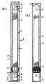
- Fig. 2 and 3 is also in the to a manifold of a capacitor attached collector (22) an insert (42) used, which contains, inter alia, a filter screen (43).
- the use (42) is designed in several parts, with the individual Parts are connected together, preferably by means of a clip connection.
- the middle part of the insert (42) consists of a tubular plastic cage (44), in the manner not shown a preferred in a bag containing dryer granules is used.
- the upper part consists of one Housing (45), in which one with a permanent magnet (46) Swinging Float (47) is arranged, with an outside to the collector arranged, not shown detector an upper Level indicator forms.
- the lower part consists of one Housing (48) similar to the housing (31) Fig.
- the filter screen (43) is between the housing (48) and the cage (44), it being in the section between the connection opening (23) and the connection opening (24), i. in a section, which is forced through by the refrigerant.
- leaf-like Slats (49) arranged in one piece with the plastic cage (44) and / or the housing (48) could be.
- These fins (49) are located inside a stocking-like filter element (50), for example may be a nonwoven, in particular a Plastic fleece, for example made of polyester.
- the filter element (50) close to the Bottom of the cage (44) is fixed so that the entire Refrigerant flows through the filter element (50).
- the filter screen (43) is a separate of the cage (42) and the housing (48) made Component is arranged between these two becomes.
- this filter screen (43) both with the cage (42) and with the housing (48) via a detachable Connection is connected, so that then the entire Insert (42) in a simple manner after opening the Lid (52) pulled out of the collector (22) can be.
- the tensioning or spreading of the leaf-spring-like fins (49) has the advantage that the Cage (42) at this point opposite the collector (22) is centered, so that its positional stability within of the collector (22) is increased.
- Cages (42) at this point opposite the collector (22) is centered, so that its positional stability within of the collector (22) is increased.
- clamping devices or spreading devices with leaf-spring-like fins (49) which are usually not there be provided with a filter element.
Description
- Fig. 1
- zeigt einen Schnitt durch einen ein Sammelrohr und einen Sammler aufweisenden Seitenbereich eines erfindungsgemäßen Kondensators,
- fig. 2
- einen Schnitt nur durch einen Sammler und
- Fig. 3
- einen Schnitt durch den Sammler der Fig. 2 und eine Ansicht auf den in dem Sammler befindlichen Einsatz in Richtung des Pfeiles III der Fig. 2.
Claims (2)
- Kondensator für eine Klimaanlage eines Fahrzeuges mit einem vom Kältemittel durchströmten Rohrrippenblock (10), der beidseits jeweils mit einem Sammelrohr (15) versehen ist, wobei parallel zu einem der Sammelrohre ein rohrförmiger Sammler (22) angeordnet ist, der mit dem zugehörigen Sammelrohr in Strömungsverbindung steht und ein Filtersieb (28) enthält, wobei
der Sammler (22) zwischen zwei Verbindungsöffnungen (23, 24) zu dem Sammelrohr (15) einen zwangsweise mit Kältemittel durchströmten Abschnitt aufweist, in welchem das Filtersieb (28) so angeordnet ist, dass das Kältemittel das Filtersieb vollständig durchströmen muss, das Filtersieb Bestandteil eines Einsatzes (29) ist, der Sammler (22) mit einer Aufnahme für einen lösbaren Deckel (27) versehen ist, nach dessen Lösen der Einsatz (29) mit dem Filtersieb (28) aus dem Sammler (22) herausnehmbar ist
und der in den Sammler eingesetzte Einsatz (29) mit einem gegenüber der Innenwand des Sammlers abdichtenden Dichtmittel (40) und mit dem Filtersieb (28) versehen ist und aus einem rohrförmigen Kunststoffkäfig besteht. - Kondensator nach Anspruch 1, dadurch gekennzeichnet, daß das Sammelrohr (15) und der Sammler (22) als eine Einheit in Form eines Doppelrohres gestaltet sind.
Applications Claiming Priority (2)
| Application Number | Priority Date | Filing Date | Title |
|---|---|---|---|
| DE4402927 | 1994-02-01 | ||
| DE4402927A DE4402927B4 (de) | 1994-02-01 | 1994-02-01 | Kondensator für eine Klimaanlage eines Fahrzeuges |
Publications (3)
| Publication Number | Publication Date |
|---|---|
| EP0669506A1 EP0669506A1 (de) | 1995-08-30 |
| EP0669506B1 EP0669506B1 (de) | 1999-07-28 |
| EP0669506B2 true EP0669506B2 (de) | 2003-11-19 |
Family
ID=6509142
Family Applications (1)
| Application Number | Title | Priority Date | Filing Date |
|---|---|---|---|
| EP95100520A Expired - Lifetime EP0669506B2 (de) | 1994-02-01 | 1995-01-17 | Kondensator für eine Klimaanlage eines Fahrzeuges |
Country Status (3)
| Country | Link |
|---|---|
| EP (1) | EP0669506B2 (de) |
| DE (2) | DE4402927B4 (de) |
| ES (1) | ES2134362T5 (de) |
Cited By (4)
| Publication number | Priority date | Publication date | Assignee | Title |
|---|---|---|---|---|
| US7043936B2 (en) | 2001-10-09 | 2006-05-16 | Behr Gmbh & Co. | Refrigerant condenser |
| US7784302B2 (en) | 2002-03-25 | 2010-08-31 | Behr France Hambach S.A.R.L. | Soldered refrigerant condenser |
| DE102011002976A1 (de) | 2011-01-21 | 2012-07-26 | Behr Gmbh & Co. Kg | Kältemittelkondensatorbaugruppe |
| US11635240B2 (en) | 2019-05-15 | 2023-04-25 | Carrier Corporation | Separator |
Families Citing this family (41)
| Publication number | Priority date | Publication date | Assignee | Title |
|---|---|---|---|---|
| DE4421834A1 (de) | 1994-06-22 | 1996-01-04 | Behr Gmbh & Co | Einsatz für einen Kondensator einer Klimaanlage eines Fahrzeuges |
| DE69626595T2 (de) * | 1995-10-18 | 2003-09-18 | Calsonic Kansei Corp | Verflüssiger mit einem Flüssigkeitsbehälter |
| FR2747768B1 (fr) * | 1996-04-18 | 1998-12-24 | Valeo Thermique Moteur Sa | Condenseur pour circuit de refrigeration, en particulier pour la climatisation d'un vehicule automobile |
| FR2749647B1 (fr) * | 1996-06-05 | 1998-08-07 | Valeo Thermique Moteur Sa | Condenseur a reservoir separe pour installation de climatisation, notamment de vehicule automobile |
| FR2750761B1 (fr) * | 1996-07-03 | 1998-10-09 | Valeo Thermique Moteur Sa | Condenseur a filtre pour installation de climatisation de vehicule automobile |
| FR2753782B1 (fr) * | 1996-09-23 | 1998-11-27 | Condenseur a reservoir integre pour un circuit de refrigeration, notamment de vehicule automobile | |
| FR2754886B1 (fr) * | 1996-10-23 | 1998-12-31 | Valeo Thermique Moteur Sa | Condenseur a tube serpentin pour circuit de refrigeration, notamment de vehicule automobile |
| FR2757612B1 (fr) * | 1996-12-23 | 1999-03-05 | Valeo Thermique Moteur Sa | Condenseur a reservoir integre perfectionne, notamment pour un circuit de climatisation de vehicule automobile |
| DE29700640U1 (de) | 1997-01-15 | 1997-05-22 | Controls Gmbh Deutsche | Fahrzeug-Klimaanlage und Trocknerpatrone für eine Fahrzeug-Klimaanlage |
| DE19800739B4 (de) * | 1997-01-31 | 2009-04-09 | Volkswagen Ag | Klimaanlage |
| DE19712714A1 (de) * | 1997-03-26 | 1998-10-01 | Behr Gmbh & Co | Einsatz für ein Sammlerprofil eines Kondensators |
| JP3508465B2 (ja) † | 1997-05-09 | 2004-03-22 | 株式会社デンソー | 熱交換器 |
| FR2764680B1 (fr) * | 1997-06-17 | 1999-08-20 | Valeo Thermique Moteur Sa | Condenseur a bloc de traitement externe, notamment pour un circuit de climatisation de vehicule automobile |
| DE29710638U1 (de) * | 1997-06-18 | 1997-08-14 | Controls Gmbh Deutsche | Aufnahmebehälter für eine Dessikativ-Charge |
| JP3801348B2 (ja) * | 1997-07-28 | 2006-07-26 | 株式会社ヴァレオサーマルシステムズ | レシーバタンク |
| DE29721546U1 (de) | 1997-12-05 | 1998-01-29 | Controls Gmbh Deutsche | Trocknerpatrone für Fahrzeug-Klimaanlage |
| DE19848744B4 (de) | 1998-10-22 | 2007-06-21 | Behr Gmbh & Co. Kg | Gelöteter Kondensator für eine Klimaanlage |
| DE19918617C2 (de) * | 1999-04-23 | 2002-01-17 | Valeo Klimatechnik Gmbh | Gaskühler für einen überkritischen CO¶2¶-Hochdruck-Kältemittelkreislauf einer Kraftfahrzeugklimaanlage |
| DE20004438U1 (de) | 2000-03-09 | 2000-06-21 | S K G Italiana S P A | Filterpatrone und Kondensator |
| US6446463B2 (en) | 2000-03-09 | 2002-09-10 | S.K.G. Italiana S.P.A. | Filter cartridge and condenser |
| EP1202007A1 (de) | 2000-10-25 | 2002-05-02 | Skg Italiana Spa | Verflüssiger und Trockner |
| JP2003028541A (ja) * | 2001-07-16 | 2003-01-29 | Sanden Corp | 熱交換器 |
| EP1319908B1 (de) * | 2001-12-12 | 2006-12-27 | Sanden Corporation | Wärmetauscher |
| CN1287122C (zh) * | 2002-03-23 | 2006-11-29 | 贝洱两合公司 | 冷凝器 |
| DE10213176A1 (de) | 2002-03-23 | 2003-10-02 | Behr Gmbh & Co | Kältmittelkondensator |
| DE10220673C1 (de) * | 2002-05-10 | 2003-07-03 | Hansa Metallwerke Ag | Filtertrocknerpatrone |
| JP2003336938A (ja) * | 2002-05-15 | 2003-11-28 | Sanden Corp | 熱交換器 |
| US6622517B1 (en) * | 2002-06-25 | 2003-09-23 | Visteon Global Technologies, Inc. | Condenser assembly having readily varied volumetrics |
| DE10234889A1 (de) * | 2002-07-31 | 2004-02-19 | Behr Gmbh & Co. | Trockner für Kältemittelkondensator |
| DE10242108B4 (de) * | 2002-09-11 | 2005-08-11 | Hansa Metallwerke Ag | Filtertrocknerpatrone für das Kondensatormodul einer Klimaanlage |
| ES2286190T3 (es) | 2002-11-15 | 2007-12-01 | Frape Behr S.A. | Condesador. |
| DE10353160A1 (de) * | 2003-11-14 | 2005-06-16 | Behr Gmbh & Co. Kg | Wärmetauscher und Sammelbehälter-Trockner-Baugruppe für Wärmetauscher |
| ES2287678T3 (es) | 2004-03-24 | 2007-12-16 | Denso Thermal Systems S.P.A. | Cartucho de filtro para sistemas de aire acondicinado de vehiculos automoviles. |
| EP1643198A1 (de) * | 2004-09-06 | 2006-04-05 | Behr France Hambach S.A.R.L. | Kondensator, insbesondere für eine Kraftfahrzeug-Klimaanlage |
| DE502005008872D1 (de) | 2005-08-24 | 2010-03-04 | Behr France Hambach Sarl | Sammelbehälter, insbesondere für einen Kondensator einer Klimaanlage, mit einem Verschluss |
| EP1762804A1 (de) | 2005-09-12 | 2007-03-14 | Frape Behr S.A. | Kältemittelkondensator |
| DE102009018901A1 (de) * | 2009-04-28 | 2010-11-04 | Deutz Ag | Rückhaltevorrichtung |
| ITMI20110252A1 (it) * | 2011-02-21 | 2012-08-22 | Skg Italia S P A | Tubo collettore per condensatori di impianti di climatizzazione per veicoli |
| EP3062042A1 (de) * | 2015-02-27 | 2016-08-31 | MAHLE International GmbH | Fluidsammler |
| CN110260566A (zh) * | 2018-03-12 | 2019-09-20 | 郑州宇通客车股份有限公司 | 一种车用空调冷凝器总成及车辆 |
| DE102021201735A1 (de) * | 2021-02-24 | 2022-08-25 | Mahle International Gmbh | Sammler eines Kältemittelkreislaufs |
Citations (8)
| Publication number | Priority date | Publication date | Assignee | Title |
|---|---|---|---|---|
| US3064819A (en) † | 1959-01-19 | 1962-11-20 | Henry Valve Co | Refrigerant drier |
| JPH02267478A (ja) † | 1989-04-05 | 1990-11-01 | Hitachi Ltd | 凝縮器 |
| US4972683A (en) † | 1989-09-01 | 1990-11-27 | Blackstone Corporation | Condenser with receiver/subcooler |
| JPH0443271A (ja) † | 1990-06-11 | 1992-02-13 | Hitachi Ltd | 凝縮器 |
| US5088294A (en) † | 1989-02-03 | 1992-02-18 | Sanden Corporation | Condenser with a built-in receiver |
| JPH04131667A (ja) † | 1990-09-25 | 1992-05-06 | Hitachi Ltd | 凝縮器 |
| US5146767A (en) † | 1991-05-13 | 1992-09-15 | General Motors Corporation | Condenser with dehydrator subcooler |
| US5228315A (en) † | 1990-12-28 | 1993-07-20 | Zexel Corporation | Condenser having a receiver tank formed integrally therewith |
Family Cites Families (11)
| Publication number | Priority date | Publication date | Assignee | Title |
|---|---|---|---|---|
| US2705405A (en) * | 1949-12-16 | 1955-04-05 | Thomas L Uhlman | Cleaner for refrigeration apparatus |
| DE1601045A1 (de) * | 1967-10-14 | 1970-06-11 | Parker Hannifin Corp | Trockenvorrichtung |
| US4745772A (en) * | 1987-04-20 | 1988-05-24 | Ferris James E | Air conditioner auxiliary filter/drier refrigerant and chemical additive transfer device |
| JP2827404B2 (ja) * | 1989-04-28 | 1998-11-25 | 株式会社デンソー | 冷媒凝縮器 |
| JP3081941B2 (ja) * | 1990-08-23 | 2000-08-28 | 株式会社ゼクセル | レシーバタンク一体型コンデンサ |
| JP3314237B2 (ja) * | 1990-09-12 | 2002-08-12 | 株式会社ゼクセル | レシーバタンク |
| JP3013492B2 (ja) * | 1990-10-04 | 2000-02-28 | 株式会社デンソー | 冷凍装置、モジュレータ付熱交換器、及び冷凍装置用モジュレータ |
| DE9116392U1 (de) * | 1991-08-23 | 1992-10-29 | Hansa Metallwerke Ag, 7000 Stuttgart, De | |
| US5245842A (en) * | 1992-05-01 | 1993-09-21 | Fayette Tubular Technology Corporation | Receiver dryer |
| DE4245046C8 (de) * | 1992-11-18 | 2008-08-21 | Behr Gmbh & Co. Kg | Kondensator für eine Klimaanlage eines Fahrzeuges |
| DE4319293C2 (de) * | 1993-06-10 | 1998-08-27 | Behr Gmbh & Co | Kondensator für eine Klimaanlage |
-
1994
- 1994-02-01 DE DE4402927A patent/DE4402927B4/de not_active Expired - Lifetime
-
1995
- 1995-01-17 ES ES95100520T patent/ES2134362T5/es not_active Expired - Lifetime
- 1995-01-17 DE DE59506428T patent/DE59506428D1/de not_active Expired - Lifetime
- 1995-01-17 EP EP95100520A patent/EP0669506B2/de not_active Expired - Lifetime
Patent Citations (8)
| Publication number | Priority date | Publication date | Assignee | Title |
|---|---|---|---|---|
| US3064819A (en) † | 1959-01-19 | 1962-11-20 | Henry Valve Co | Refrigerant drier |
| US5088294A (en) † | 1989-02-03 | 1992-02-18 | Sanden Corporation | Condenser with a built-in receiver |
| JPH02267478A (ja) † | 1989-04-05 | 1990-11-01 | Hitachi Ltd | 凝縮器 |
| US4972683A (en) † | 1989-09-01 | 1990-11-27 | Blackstone Corporation | Condenser with receiver/subcooler |
| JPH0443271A (ja) † | 1990-06-11 | 1992-02-13 | Hitachi Ltd | 凝縮器 |
| JPH04131667A (ja) † | 1990-09-25 | 1992-05-06 | Hitachi Ltd | 凝縮器 |
| US5228315A (en) † | 1990-12-28 | 1993-07-20 | Zexel Corporation | Condenser having a receiver tank formed integrally therewith |
| US5146767A (en) † | 1991-05-13 | 1992-09-15 | General Motors Corporation | Condenser with dehydrator subcooler |
Cited By (4)
| Publication number | Priority date | Publication date | Assignee | Title |
|---|---|---|---|---|
| US7043936B2 (en) | 2001-10-09 | 2006-05-16 | Behr Gmbh & Co. | Refrigerant condenser |
| US7784302B2 (en) | 2002-03-25 | 2010-08-31 | Behr France Hambach S.A.R.L. | Soldered refrigerant condenser |
| DE102011002976A1 (de) | 2011-01-21 | 2012-07-26 | Behr Gmbh & Co. Kg | Kältemittelkondensatorbaugruppe |
| US11635240B2 (en) | 2019-05-15 | 2023-04-25 | Carrier Corporation | Separator |
Also Published As
| Publication number | Publication date |
|---|---|
| DE4402927B4 (de) | 2008-02-14 |
| EP0669506A1 (de) | 1995-08-30 |
| DE59506428D1 (de) | 1999-09-02 |
| ES2134362T3 (es) | 1999-10-01 |
| EP0669506B1 (de) | 1999-07-28 |
| ES2134362T5 (es) | 2004-07-01 |
| DE4402927A1 (de) | 1995-08-03 |
Similar Documents
| Publication | Publication Date | Title |
|---|---|---|
| EP0669506B2 (de) | Kondensator für eine Klimaanlage eines Fahrzeuges | |
| DE4314917C2 (de) | Sammler für Klimaanlagen | |
| EP2129978B1 (de) | Kondensator für eine klimaanlage, insbesondere eines kraftfahrzeuges | |
| DE69916809T2 (de) | Konisch geformter luft/öl-trenner | |
| EP1147930B1 (de) | Kondensator für die Klimaanlage eines Kraftfahrzeuges | |
| DE102005005187A1 (de) | Kondensator für eine Klimaanlage, insbesondere eines Kraftfahrzeuges | |
| DE2125117C3 (de) | ||
| DE202007007120U1 (de) | Kraftstoffzuführeinrichtung, insbesondere für eine Brennkraftmaschine | |
| EP3213803A1 (de) | Filter-anordnung | |
| EP1492985A1 (de) | Kältemittelkondensator | |
| DE60017629T2 (de) | Trocknungssammler für Kälteanlagen und Verfahren zum Zusammenbauen eines solchen Sammlers | |
| EP1522804B1 (de) | Aufnahmevorrichtung für Trocknungsmittel in einem Kondensator und Kondensator | |
| DE202008005672U1 (de) | Luftentölelement | |
| DE102016203871A1 (de) | Klimaanlage | |
| WO2004099687A1 (de) | Vorrichtung zum kondensieren eines kältemittels | |
| DE19706620B4 (de) | Abtrenneinrichtung für Regenwasser | |
| EP1363089B1 (de) | Aufnahmevorrichtung für Trocknungsmittel | |
| DE102006005514B4 (de) | Luftfilter für eine Luftansaugbaugruppe mit primären und sekundären Einlässen | |
| EP1764569B1 (de) | Sammler mit Trockner-/Filtereinheit für einen Kondensator | |
| DE19916964C2 (de) | Rückhalteanlage für Niederschlagswasser und Abwasser | |
| DE102007028591A1 (de) | Akkumulator, insbesondere für eine Kraftfahrzeug- Klimaanlage | |
| DE19905354C2 (de) | Kältekreislauf mit Verflüssiger, Verdampfer und integriertem Trockenmittel | |
| DE10234889A1 (de) | Trockner für Kältemittelkondensator | |
| DE102012222664A1 (de) | Kondensator | |
| DE202008007635U1 (de) | Luftaufbereitungsvorrichtung, insbesondere einer Luftdruckbremsanlage mit einem Abscheider für flüssige Fluide |
Legal Events
| Date | Code | Title | Description |
|---|---|---|---|
| PUAI | Public reference made under article 153(3) epc to a published international application that has entered the european phase |
Free format text: ORIGINAL CODE: 0009012 |
|
| AK | Designated contracting states |
Kind code of ref document: A1 Designated state(s): DE ES FR GB IT |
|
| 17P | Request for examination filed |
Effective date: 19950920 |
|
| 17Q | First examination report despatched |
Effective date: 19970528 |
|
| GRAG | Despatch of communication of intention to grant |
Free format text: ORIGINAL CODE: EPIDOS AGRA |
|
| GRAG | Despatch of communication of intention to grant |
Free format text: ORIGINAL CODE: EPIDOS AGRA |
|
| GRAH | Despatch of communication of intention to grant a patent |
Free format text: ORIGINAL CODE: EPIDOS IGRA |
|
| ITF | It: translation for a ep patent filed |
Owner name: DE DOMINICIS & MAYER S.R.L. |
|
| GRAH | Despatch of communication of intention to grant a patent |
Free format text: ORIGINAL CODE: EPIDOS IGRA |
|
| GRAA | (expected) grant |
Free format text: ORIGINAL CODE: 0009210 |
|
| AK | Designated contracting states |
Kind code of ref document: B1 Designated state(s): DE ES FR GB IT |
|
| GBT | Gb: translation of ep patent filed (gb section 77(6)(a)/1977) |
Effective date: 19990811 |
|
| REF | Corresponds to: |
Ref document number: 59506428 Country of ref document: DE Date of ref document: 19990902 |
|
| ET | Fr: translation filed | ||
| REG | Reference to a national code |
Ref country code: ES Ref legal event code: FG2A Ref document number: 2134362 Country of ref document: ES Kind code of ref document: T3 |
|
| PLBQ | Unpublished change to opponent data |
Free format text: ORIGINAL CODE: EPIDOS OPPO |
|
| PLAV | Examination of admissibility of opposition |
Free format text: ORIGINAL CODE: EPIDOS OPEX |
|
| PLBI | Opposition filed |
Free format text: ORIGINAL CODE: 0009260 |
|
| PLBQ | Unpublished change to opponent data |
Free format text: ORIGINAL CODE: EPIDOS OPPO |
|
| PLBI | Opposition filed |
Free format text: ORIGINAL CODE: 0009260 |
|
| PLAV | Examination of admissibility of opposition |
Free format text: ORIGINAL CODE: EPIDOS OPEX |
|
| PLBF | Reply of patent proprietor to notice(s) of opposition |
Free format text: ORIGINAL CODE: EPIDOS OBSO |
|
| 26 | Opposition filed |
Opponent name: MODINE EUROPE GMBH Effective date: 20000428 |
|
| 26 | Opposition filed |
Opponent name: MODINE MANUFACTURING COMPANY Effective date: 20000428 Opponent name: MODINE EUROPE GMBH Effective date: 20000428 |
|
| PLBF | Reply of patent proprietor to notice(s) of opposition |
Free format text: ORIGINAL CODE: EPIDOS OBSO |
|
| PLAW | Interlocutory decision in opposition |
Free format text: ORIGINAL CODE: EPIDOS IDOP |
|
| APAC | Appeal dossier modified |
Free format text: ORIGINAL CODE: EPIDOS NOAPO |
|
| APAC | Appeal dossier modified |
Free format text: ORIGINAL CODE: EPIDOS NOAPO |
|
| APAE | Appeal reference modified |
Free format text: ORIGINAL CODE: EPIDOS REFNO |
|
| REG | Reference to a national code |
Ref country code: GB Ref legal event code: IF02 |
|
| APAC | Appeal dossier modified |
Free format text: ORIGINAL CODE: EPIDOS NOAPO |
|
| PLAW | Interlocutory decision in opposition |
Free format text: ORIGINAL CODE: EPIDOS IDOP |
|
| PLAW | Interlocutory decision in opposition |
Free format text: ORIGINAL CODE: EPIDOS IDOP |
|
| PUAH | Patent maintained in amended form |
Free format text: ORIGINAL CODE: 0009272 |
|
| STAA | Information on the status of an ep patent application or granted ep patent |
Free format text: STATUS: PATENT MAINTAINED AS AMENDED |
|
| 27A | Patent maintained in amended form |
Effective date: 20031119 |
|
| AK | Designated contracting states |
Kind code of ref document: B2 Designated state(s): DE ES FR GB IT |
|
| REG | Reference to a national code |
Ref country code: ES Ref legal event code: DC2A Date of ref document: 20040204 Kind code of ref document: T5 |
|
| ET3 | Fr: translation filed ** decision concerning opposition | ||
| REG | Reference to a national code |
Ref country code: FR Ref legal event code: CD |
|
| APAH | Appeal reference modified |
Free format text: ORIGINAL CODE: EPIDOSCREFNO |
|
| REG | Reference to a national code |
Ref country code: ES Ref legal event code: PC2A |
|
| PGFP | Annual fee paid to national office [announced via postgrant information from national office to epo] |
Ref country code: ES Payment date: 20080122 Year of fee payment: 14 |
|
| PGFP | Annual fee paid to national office [announced via postgrant information from national office to epo] |
Ref country code: IT Payment date: 20080123 Year of fee payment: 14 |
|
| REG | Reference to a national code |
Ref country code: ES Ref legal event code: FD2A Effective date: 20090119 |
|
| PG25 | Lapsed in a contracting state [announced via postgrant information from national office to epo] |
Ref country code: ES Free format text: LAPSE BECAUSE OF NON-PAYMENT OF DUE FEES Effective date: 20090119 |
|
| PGFP | Annual fee paid to national office [announced via postgrant information from national office to epo] |
Ref country code: FR Payment date: 20100210 Year of fee payment: 16 |
|
| PGFP | Annual fee paid to national office [announced via postgrant information from national office to epo] |
Ref country code: GB Payment date: 20100121 Year of fee payment: 16 |
|
| PG25 | Lapsed in a contracting state [announced via postgrant information from national office to epo] |
Ref country code: IT Free format text: LAPSE BECAUSE OF NON-PAYMENT OF DUE FEES Effective date: 20090117 |
|
| GBPC | Gb: european patent ceased through non-payment of renewal fee |
Effective date: 20110117 |
|
| REG | Reference to a national code |
Ref country code: FR Ref legal event code: ST Effective date: 20110930 |
|
| PG25 | Lapsed in a contracting state [announced via postgrant information from national office to epo] |
Ref country code: FR Free format text: LAPSE BECAUSE OF NON-PAYMENT OF DUE FEES Effective date: 20110131 |
|
| PG25 | Lapsed in a contracting state [announced via postgrant information from national office to epo] |
Ref country code: GB Free format text: LAPSE BECAUSE OF NON-PAYMENT OF DUE FEES Effective date: 20110117 |
|
| REG | Reference to a national code |
Ref country code: DE Ref legal event code: R082 Ref document number: 59506428 Country of ref document: DE Representative=s name: GRAUEL, ANDREAS, DIPL.-PHYS. DR. RER. NAT., DE Ref country code: DE Ref legal event code: R082 Ref document number: 59506428 Country of ref document: DE Representative=s name: ANDREAS GRAUEL, DE |
|
| PGFP | Annual fee paid to national office [announced via postgrant information from national office to epo] |
Ref country code: DE Payment date: 20140203 Year of fee payment: 20 |
|
| REG | Reference to a national code |
Ref country code: DE Ref legal event code: R071 Ref document number: 59506428 Country of ref document: DE |
|
| REG | Reference to a national code |
Ref country code: DE Ref legal event code: R071 Ref document number: 59506428 Country of ref document: DE |
|
| REG | Reference to a national code |
Ref country code: DE Ref legal event code: R082 Ref document number: 59506428 Country of ref document: DE Representative=s name: GRAUEL, ANDREAS, DIPL.-PHYS. DR. RER. NAT., DE |
|
| REG | Reference to a national code |
Ref country code: DE Ref legal event code: R082 Ref document number: 59506428 Country of ref document: DE Representative=s name: GRAUEL, ANDREAS, DIPL.-PHYS. DR. RER. NAT., DE Effective date: 20150305 Ref country code: DE Ref legal event code: R082 Ref document number: 59506428 Country of ref document: DE Representative=s name: GRAUEL, ANDREAS, DIPL.-PHYS. DR. RER. NAT., DE Effective date: 20120108 Ref country code: DE Ref legal event code: R081 Ref document number: 59506428 Country of ref document: DE Owner name: MAHLE INTERNATIONAL GMBH, DE Free format text: FORMER OWNER: BEHR GMBH & CO. KG, 70469 STUTTGART, DE Effective date: 20150305 |