EP0669506B2 - Condenser for an air conditioning equipment of a vehicle - Google Patents
Condenser for an air conditioning equipment of a vehicle Download PDFInfo
- Publication number
- EP0669506B2 EP0669506B2 EP95100520A EP95100520A EP0669506B2 EP 0669506 B2 EP0669506 B2 EP 0669506B2 EP 95100520 A EP95100520 A EP 95100520A EP 95100520 A EP95100520 A EP 95100520A EP 0669506 B2 EP0669506 B2 EP 0669506B2
- Authority
- EP
- European Patent Office
- Prior art keywords
- collector
- collecting means
- gauze filter
- pipe
- condenser
- Prior art date
- Legal status (The legal status is an assumption and is not a legal conclusion. Google has not performed a legal analysis and makes no representation as to the accuracy of the status listed.)
- Expired - Lifetime
Links
Images
Classifications
-
- F—MECHANICAL ENGINEERING; LIGHTING; HEATING; WEAPONS; BLASTING
- F25—REFRIGERATION OR COOLING; COMBINED HEATING AND REFRIGERATION SYSTEMS; HEAT PUMP SYSTEMS; MANUFACTURE OR STORAGE OF ICE; LIQUEFACTION SOLIDIFICATION OF GASES
- F25B—REFRIGERATION MACHINES, PLANTS OR SYSTEMS; COMBINED HEATING AND REFRIGERATION SYSTEMS; HEAT PUMP SYSTEMS
- F25B39/00—Evaporators; Condensers
- F25B39/04—Condensers
-
- B—PERFORMING OPERATIONS; TRANSPORTING
- B60—VEHICLES IN GENERAL
- B60H—ARRANGEMENTS OF HEATING, COOLING, VENTILATING OR OTHER AIR-TREATING DEVICES SPECIALLY ADAPTED FOR PASSENGER OR GOODS SPACES OF VEHICLES
- B60H1/00—Heating, cooling or ventilating [HVAC] devices
- B60H1/32—Cooling devices
- B60H1/3204—Cooling devices using compression
- B60H1/3227—Cooling devices using compression characterised by the arrangement or the type of heat exchanger, e.g. condenser, evaporator
-
- B—PERFORMING OPERATIONS; TRANSPORTING
- B60—VEHICLES IN GENERAL
- B60H—ARRANGEMENTS OF HEATING, COOLING, VENTILATING OR OTHER AIR-TREATING DEVICES SPECIALLY ADAPTED FOR PASSENGER OR GOODS SPACES OF VEHICLES
- B60H1/00—Heating, cooling or ventilating [HVAC] devices
- B60H1/32—Cooling devices
- B60H1/3204—Cooling devices using compression
- B60H1/3229—Cooling devices using compression characterised by constructional features, e.g. housings, mountings, conversion systems
-
- F—MECHANICAL ENGINEERING; LIGHTING; HEATING; WEAPONS; BLASTING
- F25—REFRIGERATION OR COOLING; COMBINED HEATING AND REFRIGERATION SYSTEMS; HEAT PUMP SYSTEMS; MANUFACTURE OR STORAGE OF ICE; LIQUEFACTION SOLIDIFICATION OF GASES
- F25B—REFRIGERATION MACHINES, PLANTS OR SYSTEMS; COMBINED HEATING AND REFRIGERATION SYSTEMS; HEAT PUMP SYSTEMS
- F25B43/00—Arrangements for separating or purifying gases or liquids; Arrangements for vaporising the residuum of liquid refrigerant, e.g. by heat
- F25B43/003—Filters
-
- F—MECHANICAL ENGINEERING; LIGHTING; HEATING; WEAPONS; BLASTING
- F25—REFRIGERATION OR COOLING; COMBINED HEATING AND REFRIGERATION SYSTEMS; HEAT PUMP SYSTEMS; MANUFACTURE OR STORAGE OF ICE; LIQUEFACTION SOLIDIFICATION OF GASES
- F25B—REFRIGERATION MACHINES, PLANTS OR SYSTEMS; COMBINED HEATING AND REFRIGERATION SYSTEMS; HEAT PUMP SYSTEMS
- F25B2339/00—Details of evaporators; Details of condensers
- F25B2339/04—Details of condensers
- F25B2339/044—Condensers with an integrated receiver
- F25B2339/0441—Condensers with an integrated receiver containing a drier or a filter
-
- F—MECHANICAL ENGINEERING; LIGHTING; HEATING; WEAPONS; BLASTING
- F25—REFRIGERATION OR COOLING; COMBINED HEATING AND REFRIGERATION SYSTEMS; HEAT PUMP SYSTEMS; MANUFACTURE OR STORAGE OF ICE; LIQUEFACTION SOLIDIFICATION OF GASES
- F25B—REFRIGERATION MACHINES, PLANTS OR SYSTEMS; COMBINED HEATING AND REFRIGERATION SYSTEMS; HEAT PUMP SYSTEMS
- F25B2400/00—General features or devices for refrigeration machines, plants or systems, combined heating and refrigeration systems or heat-pump systems, i.e. not limited to a particular subgroup of F25B
- F25B2400/16—Receivers
- F25B2400/162—Receivers characterised by the plug or stop
-
- F—MECHANICAL ENGINEERING; LIGHTING; HEATING; WEAPONS; BLASTING
- F25—REFRIGERATION OR COOLING; COMBINED HEATING AND REFRIGERATION SYSTEMS; HEAT PUMP SYSTEMS; MANUFACTURE OR STORAGE OF ICE; LIQUEFACTION SOLIDIFICATION OF GASES
- F25B—REFRIGERATION MACHINES, PLANTS OR SYSTEMS; COMBINED HEATING AND REFRIGERATION SYSTEMS; HEAT PUMP SYSTEMS
- F25B40/00—Subcoolers, desuperheaters or superheaters
- F25B40/02—Subcoolers
Definitions
- the invention relates to a capacitor for a Air conditioning of a vehicle with a refrigerant flowed through tube-rib block, the both sides each provided with a manifold, wherein parallel to one of the manifolds a tubular Collector is arranged, with the associated manifold is in flow communication and a filter screen contains.
- the invention is based on the object, a Condenser of the type mentioned above, that the functionality due to a Maintenance is improved.
- the filter screen is easily accessible and exchangeable. It is possible by means of a simple Maintenance process the condition of the filter screen to review and if necessary to improve the Function of the air conditioning or to maintain to replace the function.
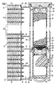
- Fig. 1 capacitor has a tube-rib block (10) from a Variety of flat tubes (11) and corrugated fins (12).
- the each outermost corrugated ribs (12) are by means of a final sheet (13) covered.
- the ends of the flat tubes (11) are in a grounded floor (14) inserted, which also for the ends of the flat tubes on the opposite side, not shown applies.
- the floors (14) are covered by covers Hoppers (15) closed by End walls (16, 17) and partitions (18, 19, 20) are divided.
- a pipe profile (21) is provided, the for example, according to the not previously published DE patent application 43 19 293.9 an extruded Can be tubular profile, on soft the edges of the floor (14). In this way becomes a double pipe formed, on the one hand as a manifold (15) serves and on the other hand as a parallel arranged Collector (22), with the manifold (15) a Unit forms.
- the collecting pipe (15) is in front of the dividing wall (19) with a connection opening (23) to the collector (22) open.
- the refrigerant is in the lower area of the Condenser in a subcooling again meandering, after which it is out of the area of the manifold (15) between the partitions (19, 20) to the opposite side to a refrigerant outlet arrives.
- the tube profile (21) of the collector (22) has substantially the same height as the ground (14), i.e. the collector (22) spans the whole Height of the capacitor.
- the lower end of the pipe profile (21) is by means of an inserted, cup-shaped Bodens (25) closed.
- the upper end of the Pipe profile (21) is having an internal thread Version (26) provided as a receptacle for a detachable lid (27) is used.
- the collector (22) is in the section between the connection openings (23, 24), the forced flows through the refrigerant, with a Filter filter (28) provided.
- This filter screen (28) cleans the usually liquid refrigerant in this area of particles caused by abrasion or the like. into the refrigerant so that the refrigerant is purified when it is leaves the condenser.
- the filter screen (28) is part of an insert (29), with the lid open (27) inserted and after opening the lid (27) in a simple manner removable is.
- the insert consists of a tubular Plastic cage (30) into which the filter screen (28) for example injected.
- this plastic cage (30) is a substantially corresponding Exterior dimensions housing (31) attached by means of a latching connection, containing a pivotally mounted float (32), the one permanent magnet (33) carries on the the outside of the collector (22) associated with a detector (34) is.
- a level detector created an air conditioner on a underfill monitored with refrigerant.
- the cage (30) In the cage (30) is a bag (35) made of refrigerant permeable Material housed, the one Contains dryer granules (36).
- the cage (30) is with a Lid (37) provided on the outside with a hemispherical Thickening (38) is provided, which is a conical Recess of the lid (27) assigned is.
- the closed lid (27) thus centered the Insert (29).
- the lower end of the housing (21), the is attached to the cage (30) is with a frusto-conical Ground (39), which is located inside the cup-shaped bottom (25) of the collector (22) centered.
- the filter screen (28) is located in an area of the cage (30), which is a closed perimeter having. In this area is a sealing ring (40) in inserted a circumferential annular groove of the cage (30), the one in the collector (22) soldered inside ring seat (41) is assigned. That from the connection opening (23) refrigerant flowing to the communication port (24) must thus completely flow through the filter screen (28). From the connection opening (24) thus flows a dried and cleaned refrigerant into the subcooling section of the tube-rib block (10).
- a sealing ring (40) instead of a sealing ring (40) a sealing ring with a to the inner wall the collector (22) applying lip provided is, so that then dispensed with a ring seat (41) can.
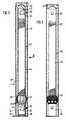
- Fig. 2 and 3 is also in the to a manifold of a capacitor attached collector (22) an insert (42) used, which contains, inter alia, a filter screen (43).
- the use (42) is designed in several parts, with the individual Parts are connected together, preferably by means of a clip connection.
- the middle part of the insert (42) consists of a tubular plastic cage (44), in the manner not shown a preferred in a bag containing dryer granules is used.
- the upper part consists of one Housing (45), in which one with a permanent magnet (46) Swinging Float (47) is arranged, with an outside to the collector arranged, not shown detector an upper Level indicator forms.
- the lower part consists of one Housing (48) similar to the housing (31) Fig.
- the filter screen (43) is between the housing (48) and the cage (44), it being in the section between the connection opening (23) and the connection opening (24), i. in a section, which is forced through by the refrigerant.
- leaf-like Slats (49) arranged in one piece with the plastic cage (44) and / or the housing (48) could be.
- These fins (49) are located inside a stocking-like filter element (50), for example may be a nonwoven, in particular a Plastic fleece, for example made of polyester.
- the filter element (50) close to the Bottom of the cage (44) is fixed so that the entire Refrigerant flows through the filter element (50).
- the filter screen (43) is a separate of the cage (42) and the housing (48) made Component is arranged between these two becomes.
- this filter screen (43) both with the cage (42) and with the housing (48) via a detachable Connection is connected, so that then the entire Insert (42) in a simple manner after opening the Lid (52) pulled out of the collector (22) can be.
- the tensioning or spreading of the leaf-spring-like fins (49) has the advantage that the Cage (42) at this point opposite the collector (22) is centered, so that its positional stability within of the collector (22) is increased.
- Cages (42) at this point opposite the collector (22) is centered, so that its positional stability within of the collector (22) is increased.
- clamping devices or spreading devices with leaf-spring-like fins (49) which are usually not there be provided with a filter element.
Description
Die Erfindung betrifft einen Kondensator für eine Klimaanlage eines Fahrzeuges mit einem von Kältemittel durchströmten Rohr-Rippen-Block, der beidseits jeweils mit einem Sammelrohr versehen ist, wobei parallel zu einem der Sammelrohre ein rohrförmiger Sammlerangeordnet ist, der mit dem zugehörigen Sammelrohr in Strömungsverbindung steht und ein Filtersieb enthält.The invention relates to a capacitor for a Air conditioning of a vehicle with a refrigerant flowed through tube-rib block, the both sides each provided with a manifold, wherein parallel to one of the manifolds a tubular Collector is arranged, with the associated manifold is in flow communication and a filter screen contains.
Aus der US-A 5 159 821 ist ein Kondensator der eingangs genannten Art bekannt. Bei dieser Bauart schließt an den Boden eines Sammelrohres ein Führungsrohr an, das durch den Boden des zugehörigen Sammlers hindurch nach oben in diesen Sammler hineinführt und sich bis zu einem unlösbar an dem Sammler befestigten Deckel erstreckt. Das Rohr durchdringt dabei einen Filter, der nach unten auf einem Ringbund des Rohres abgestützt ist. In dem Sammler oberhalb des Filters befindet sich ein Trocknermaterial. Das Rohr ist in dem oberhalb des Filters befindlichen Abschnitt perforiert, so daß dort Kältemittel aus ihm austreten kann, das dann durch das Trocknermaterial hindurch und durch das Filtersieb hindurch in den Bereich des unteren Endes des Sammlers gelangen kann, aus welchem es mittels eines Abflußrohres zu einem Expansionsventil geführt wird. Das Filtersieb und das Trocknermaterial sind für eine Wartung o.dgl. nicht zugänglich.From US-A 5 159 821 is a capacitor of the aforementioned type known. With this type closes at the bottom of a manifold a guide tube that goes through the bottom of the associated one Through Collector leads up into this collector and become insoluble in the collector extends fixed lid. The pipe penetrates doing a filter that is down on a collar supported by the tube. In the collector above of the filter is a dryer material. The pipe is in the section above the filter perforated, so that there leak refrigerant from it can then pass through the dryer material and through the filter screen into the area of the lower end of the collector can get out of which it by means of a drain pipe to an expansion valve to be led. The filter screen and the dryer material are for maintenance or the like. inaccessible.
Der Erfindung liegt die Aufgabe zugrunde, einen Kondensator der eingangs genannten Art so weiterzubilden, daß die Funktionsfähigkeit aufgrund einer Wartungsmöglichkeit verbessert ist.The invention is based on the object, a Condenser of the type mentioned above, that the functionality due to a Maintenance is improved.
Diese Aufgabe wird durch die Merkmale des Patentanspruchs 1 gelöst.This object is solved by the features of patent claim 1.
Aufgrund der erfindungsgemäßen Ausbildung ist das Filtersieb in einfacher Weise zugänglich undaustauschbar. Es ist dadurch möglich, mittels eines einfachen Wartungsvorganges den Zustand des Filtersiebes zu überprüfen und gegebenenfalls zum Verbessern der Funktion der Klimaanlage oder zur Aufrechterhaltung der Funktion auszutauschen.Due to the inventive design the filter screen is easily accessible and exchangeable. It is possible by means of a simple Maintenance process the condition of the filter screen to review and if necessary to improve the Function of the air conditioning or to maintain to replace the function.
Es wird auch sichergestellt, daß die gesamte Kältemittelmenge durch das Filtersieb strömt, so daß das Kältemittel wirksam gereinigt ist.It also ensures that the total amount of refrigerant flows through the filter screen, so that the refrigerant is effectively cleaned.
Weitere Vorteile und Merkmale der Erfindung ergeben sich aus der nachfolgenden Beschreibung der in den Zeichnungen dargestellten Ausführungsbeispielen
- Fig. 1
- zeigt einen Schnitt durch einen ein Sammelrohr und einen Sammler aufweisenden Seitenbereich eines erfindungsgemäßen Kondensators,
- fig. 2
- einen Schnitt nur durch einen Sammler und
- Fig. 3
- einen Schnitt durch den Sammler der Fig. 2 und eine Ansicht auf den in dem Sammler befindlichen Einsatz in Richtung des Pfeiles III der Fig. 2.
- Fig. 1
- shows a section through a collecting pipe and a collector having side portion of a capacitor according to the invention,
- fig. 2
- a cut only by a collector and
- Fig. 3
- 2 shows a section through the collector of FIG. 2 and a view of the insert located in the collector in the direction of the arrow III of FIG. 2.
Der in Fig. 1 nur zum Teil dargestellte Kondensator besitzt einen Rohr-Rippen-Block (10) aus einer Vielzahl von Flachrohren (11) und Wellrippen (12). Die jeweils äußersten Wellrippen (12) sind mittels eines Abschlußbleches (13) abgedeckt. Die Enden der Flachrohre (11) sind in einen mit Durchzügen versehenen Boden (14) eingesteckt, was auch für die Enden der Flachrohre auf der gegenüberliegenden, nicht dargestellten Seite gilt. Die Böden (14) werden mittels Abdeckungen zu Sammelrohren (15) geschlossen, die durch Abschlußwände (16, 17) und Trennwände (18, 19, 20) unterteilt sind.The only partially shown in Fig. 1 capacitor has a tube-rib block (10) from a Variety of flat tubes (11) and corrugated fins (12). The each outermost corrugated ribs (12) are by means of a final sheet (13) covered. The ends of the flat tubes (11) are in a grounded floor (14) inserted, which also for the ends of the flat tubes on the opposite side, not shown applies. The floors (14) are covered by covers Hoppers (15) closed by End walls (16, 17) and partitions (18, 19, 20) are divided.
Der Boden der in Fig.1 nicht dargestellten Seite
wird beispielsweise mittels eines Abschlußbleches
verschlossen. Zum Verschluß des Bodens (14), der in
Fig. 1 sichtbar ist, ist ein Rohrprofil (21) vorgesehen, das
beispielsweise entsprechend der nicht vorveröffentlichten
DE-Patentanmeldung 43 19 293.9 ein extrudiertes
Rohrprofil sein kann, an weiches die Ränder des Bodens
(14) anschließen. Auf diese Weise wird ein Doppelrohr
gebildet, das zum einen als Sammelrohr (15)
dient und zum anderen als ein parallel dazu angeordneter
Sammler (22), der mit dem Sammelrohr (15) eine
Einheit bildet. Die Trennwände (18, 19, 20) unterteilen
das Sammelrohr (15) und das nicht dargestellte gegenüberliegende
Sammelrohr derart, daß das oben zugeführte,
dampfförmige Kältemittel mäanderförmig durch
den Rohr-Rippen-Block (10) strömt, wobei die Aufteilung
mittels der Trennwände (18, 19, 20) derart gewählt
ist, daß entsprechend der zunehmenden Kondensierung
die Strömungsquerschnitte verringert werden.The bottom of the not shown in Figure 1 page
is for example by means of a final sheet
locked. For closing the bottom (14), the in
Fig. 1 is visible, a pipe profile (21) is provided, the
for example, according to the not previously published
Das Sammelrohr (15) ist vor der Trennwand (19) mit einer Verbindungsöffnung (23) zu dem Sammler (22) hin offen. Das dort bereits schon flüssige Kältemittel strömt über diese Verbindungsöffnung (23) zu dem Sammler (22), von welchem es über eine untere Verbindungsöffnung (24) zu dem Sammelrohr (15) zurück strömt. Das Kältemittel wird in dem unteren Bereich des Kondensators in einer Unterkühlstrecke noch einmal mäanderförmig geführt, wonach es aus dem Bereich des Sammelrohres (15) zwischen den Trennwänden (19, 20) zur gegenüberliegenden Seite zu einem Kältemittelauslaß gelangt.The collecting pipe (15) is in front of the dividing wall (19) with a connection opening (23) to the collector (22) open. The already liquid refrigerant there flows through this connection opening (23) to the Collector (22), from which it has a lower connection opening (24) back to the manifold (15) flows. The refrigerant is in the lower area of the Condenser in a subcooling again meandering, after which it is out of the area of the manifold (15) between the partitions (19, 20) to the opposite side to a refrigerant outlet arrives.
Das Rohrprofil (21) des Sammlers (22) besitzt im wesentlichen die gleiche Höhe wie der Boden (14), d.h. der Sammler (22) erstreckt sich über die gesamte Höhe des Kondensators. Das untere Ende des Rohrprofils (21) ist mittels eines eingesetzten, schalenförmigen Bodens (25) verschlossen. Das obere Ende des Rohrprofils (21) ist mit einer ein Innengewinde aufweisenden Fassung (26) versehen, die als Aufnahme für einen lösbaren Deckel (27) dient.The tube profile (21) of the collector (22) has substantially the same height as the ground (14), i.e. the collector (22) spans the whole Height of the capacitor. The lower end of the pipe profile (21) is by means of an inserted, cup-shaped Bodens (25) closed. The upper end of the Pipe profile (21) is having an internal thread Version (26) provided as a receptacle for a detachable lid (27) is used.
Bei der Herstellung des Kondensators wird der Rchr-Rippen-Block (10) mit den Boden (14), den Abschlußwänden (16,17), den Trennwänden (18, 19, 20) sowie mit dem Rohrprofil (21), dessen Boden (25) und dessen Fassung (26) sowie auf der gegenüberliegenden Seite mit einem Abschluß für den dort befindlichen Boden paketiert und dann in einem Ofen gelötet. Hierzu sind die aus Aluminium oder Aluminiumlegierungen hergestellten Elemente zweckmäßigerweise mit einer Lotplattierung versehen.In the manufacture of the capacitor of the Rr-rib block (10) with the bottom (14), the end walls (16,17), the partitions (18, 19, 20) and with the tube profile (21), the bottom (25) and its version (26) and on the opposite Page with a conclusion for the one there Packed soil and then soldered in an oven. For this are made of aluminum or aluminum alloys Elements expediently with a Lotplattierung Provided.
Der Sammler (22) ist in dem Abschnitt zwischen den Verbindungsöffnungen (23, 24), der zwangsweise von dem Kältemittel durchströmt wird, mit einem Filtersieb (28) versehen. Dieses Filtersieb (28) reinigt das in diesem Bereich in der Regel flüssige Kältemittel von Partikeln, die durch Abrieb o.dgl. in das Kältemittel gelangen, so daß das Kältemittel gereinigt ist, wenn es den Kondensator verläßt.The collector (22) is in the section between the connection openings (23, 24), the forced flows through the refrigerant, with a Filter filter (28) provided. This filter screen (28) cleans the usually liquid refrigerant in this area of particles caused by abrasion or the like. into the refrigerant so that the refrigerant is purified when it is leaves the condenser.
Das Filtersieb (28) ist Bestandteil eines Einsatzes (29), der bei offenem Deckel (27) eingesetzt und nach Öffnen des Deckels (27) in einfacher Weise herausnehmbar ist. Der Einsatz besteht aus einem rohrförmigen Kunststoffkäfig (30), in den das Filtersieb (28) beispielsweise eingespritzt ist. An dem unteren Ende dieses Kunststoffkäfigs (30) ist ein im wesentlichen entsprechende Außenabmessungen aufweisendes Gehäuse (31) mittels einer Rastverbindung angebracht, das einen schwenkbar gelagerten Schwimmer (32) enthält, der einen Permanentmagneten (33) trägt, dem auf der Außenseite des Sammlers (22) ein Detektor (34) zugeordnet ist. Auf diese Weise wird ein Füllstandsdetektor geschaffen, der eine Klimaanlage auf eine Unterfüllung mit Kältemittel überwacht.The filter screen (28) is part of an insert (29), with the lid open (27) inserted and after opening the lid (27) in a simple manner removable is. The insert consists of a tubular Plastic cage (30) into which the filter screen (28) for example injected. At the bottom this plastic cage (30) is a substantially corresponding Exterior dimensions housing (31) attached by means of a latching connection, containing a pivotally mounted float (32), the one permanent magnet (33) carries on the the outside of the collector (22) associated with a detector (34) is. In this way, a level detector created an air conditioner on a underfill monitored with refrigerant.
In dem Käfig (30) ist ein Säckchen (35) aus kältemitteldurchlässigem Material untergebracht, das ein Trocknergranulat (36) enthält. Der Käfig (30) ist mit einem Deckel (37) versehen, der außen mit einer halbkugelförmigen Verdickung (38) versehen ist, der eine kegelförmige Aussparung des Deckels (27) zugeordnet ist. Der geschlossene Deckel (27) zentriert somit den Einsatz (29). Das untere Ende des Gehäuses (21), das an dem Käfig (30) befestigt ist, ist mit einem kegelstumpfförmigen Boden (39) versehen, der sich innen an dem schalenförmigen Boden (25) des Sammlers (22) zentriert.In the cage (30) is a bag (35) made of refrigerant permeable Material housed, the one Contains dryer granules (36). The cage (30) is with a Lid (37) provided on the outside with a hemispherical Thickening (38) is provided, which is a conical Recess of the lid (27) assigned is. The closed lid (27) thus centered the Insert (29). The lower end of the housing (21), the is attached to the cage (30) is with a frusto-conical Ground (39), which is located inside the cup-shaped bottom (25) of the collector (22) centered.
Das Filtersieb (28) befindet sich in einem Bereich des Käfigs (30), der einen geschlossenen Umfang aufweist. In diesem Bereich ist ein Dichtungsring (40) in eine umlaufende Ringnut des Käfigs (30) eingesetzt, der ein in den Sammler (22) innen eingelöteter Ringsitz (41) zugeordnet ist. Das von der Verbindungsöffnung (23) zu der Verbindungsöffnung (24) strömende Kältemittel muß somit das Filtersieb (28) vollständig durchströmen. Aus der Verbindungsöffnung (24) strömt somit ein getrocknetes und gereinigtes Kältemittel in die Unterkühlstrecke des Rohr-Rippen-Blockes (10) ab.The filter screen (28) is located in an area of the cage (30), which is a closed perimeter having. In this area is a sealing ring (40) in inserted a circumferential annular groove of the cage (30), the one in the collector (22) soldered inside ring seat (41) is assigned. That from the connection opening (23) refrigerant flowing to the communication port (24) must thus completely flow through the filter screen (28). From the connection opening (24) thus flows a dried and cleaned refrigerant into the subcooling section of the tube-rib block (10).
Bei einer abgewandelten Ausführungsform wird vorgesehen, daß anstelle eines Dichtungsringes (40) ein Dichtungsring mit einer sich an die Innenwandung des Sammlers (22) anlegender Lippe vorgesehen wird, so daß dann auf einen Ringsitz (41) verzichtet werden kann.In a modified embodiment is provided that instead of a sealing ring (40) a sealing ring with a to the inner wall the collector (22) applying lip provided is, so that then dispensed with a ring seat (41) can.
Bei der Ausführungsform nach Fig. 2 und 3 ist ebenfalls in den an ein Sammelrohr eines Kondensators angefügten Sammler (22) ein Einsatz (42) eingesetzt, der unter anderem ein Filtersieb (43) enthält. Der Einsatz (42) ist mehrteilig ausgebildet, wobei die einzelnen Teile miteinander verbunden sind, vorzugsweise mittels einer Klipsverbindung. Der mittlere Teil des Einsatzes (42) besteht aus einem rohrförmigen Kunststoffkäfig (44), in den in nicht näher dargestellter Weise ein vorzugsweise in einem Säckchen enthaltendes Trocknergranulat eingesetzt ist. Derobere Teil besteht aus einem Gehäuse (45), in welchem ein mit einem Permanentmagneten (46) versehener, schwenkbarer Schwimmer (47) angeordnet ist, der mit einem außen an den Sammler angeordneten, nicht dargestellten Detektor eine obere Füllstandsanzeige bildet. Der untere Teil besteht aus einem Gehäuse (48), das ähnlich zu dem Gehäuse (31) der Fig. 1 gestaltet sein kann. Es enthält einen Schwimmer (32) mit einem Permanentmagneten (33), der zu einer die Minimalbefüllung angebenden Füllstandsanzeige gehört. Das Filtersieb (43) ist zwischen dem Gehäuse (48) und dem Käfig (44) angeordnet, wobei es in dem Abschnitt zwischen der Verbindungsöffnung (23) und der Verbindungsöffnung (24) liegt, d.h. in einem Abschnitt, der von dem Kältemittel zwangsdurchströmt ist.In the embodiment of Fig. 2 and 3 is also in the to a manifold of a capacitor attached collector (22) an insert (42) used, which contains, inter alia, a filter screen (43). The use (42) is designed in several parts, with the individual Parts are connected together, preferably by means of a clip connection. The middle part of the insert (42) consists of a tubular plastic cage (44), in the manner not shown a preferred in a bag containing dryer granules is used. The upper part consists of one Housing (45), in which one with a permanent magnet (46) Swinging Float (47) is arranged, with an outside to the collector arranged, not shown detector an upper Level indicator forms. The lower part consists of one Housing (48) similar to the housing (31) Fig. 1 can be designed. It contains a float (32) with a permanent magnet (33) attached to a level indicator indicating the minimum filling belongs. The filter screen (43) is between the housing (48) and the cage (44), it being in the section between the connection opening (23) and the connection opening (24), i. in a section, which is forced through by the refrigerant.
Zwischen dem Käfig (44) und dem Gehäuse (48) sind leicht nach außen gewölbte, blattfederartige Lamellen (49) angeordnet, die einteilig mit dem Kunststoffkäfig (44) und/oder dem Gehäuse (48) hergestellt sein können. Diese Lamellen (49) befinden sich innerhalb eines strumpfartigen Filterelementes (50), das beispielsweise ein Vlies sein kann, insbesondere ein Kunststoffvlies, beispielsweise aus Polyester.Between the cage (44) and the housing (48) are slightly domed, leaf-like Slats (49) arranged in one piece with the plastic cage (44) and / or the housing (48) could be. These fins (49) are located inside a stocking-like filter element (50), for example may be a nonwoven, in particular a Plastic fleece, for example made of polyester.
In entspanntem Zustand der Lamellen (49) hat der gesamte Einsatz (42) eine axiale Länge, die etwas größer als der axiale Abstand zwischen dem Boden (51) des Sammlers und einem an dem oberen Ende befestigten Deckels (52) ist, wenn dieser Deckel (52) sich in seiner Schließposition befindet. Durch Schließen des Deckels (52), für den eine Schraubverbindung oder Bajonettverbindung o.dgl. vorgesehen wird, wird der Einsatz (42) in axialer Richtung zusammengedrückt ( Fig. 3), so daß die Lamellen (49) nach außen gespreizt werden. Sie spannen dabei das Filterelement (50) schirmartig auf, so daß es den freien Strömungsbereich zwischen der Verbindungsöffnung (23) und der Verbindungsöffnung (24) vollständig einnimmt, da es an die Innenwandungen des Sammlers (22) angedrückt wird. Wie aus Fig. 3 zu ersehen ist, kann das Filterelement (50) in Richtung zu der Verbindungsöffnung (24) nach seiner Anlagestelle der Innenwandung des Sammlers (22) mit Durchbrechungen versehen sein, so daß das Kältemittel das Filterelement (50) nur einmal durchströmen muß.In the relaxed state of the fins (49) has the entire insert (42) has an axial length, which is something greater than the axial distance between the floor (51) of the collector and one attached to the top Cover (52) is when this cover (52) in is located in its closed position. By closing the Lid (52) for which a screw connection or bayonet connection or the like. is provided, the use becomes (42) compressed in the axial direction (Fig. 3), so that the fins (49) are spread outwards. They clamp the filter element (50) like an umbrella on, so that there is the free flow area between the connection opening (23) and the connection opening (24) completely occupies, as it to the Inner walls of the collector (22) is pressed. As can be seen from Fig. 3, the filter element (50) towards the connection opening (24) its contact point of the inner wall of the collector (22) be provided with openings, so that the Refrigerant flow through the filter element (50) only once got to.
Bei dem dargestellten Ausführungsbeispiel ist vorgesehen, daß das Filterelement (50) dicht an dem Boden des Käfigs (44) befestigt ist, so daß das gesamte Kältemittel durch das Filterelement (50) strömt.In the illustrated embodiment is provided that the filter element (50) close to the Bottom of the cage (44) is fixed so that the entire Refrigerant flows through the filter element (50).
Bei einer abgewandelten Ausführungsform wird vorgesehen, daß das Filtersieb (43) ein getrennt von dem Käfig (42) und dem Gehäuse (48) hergestelltes Bauteil ist, das zwischen diesen beiden angeordnet wird. In diesem Fall wird zweckmäßigerweise vorgesehen, daß dieses Filtersieb (43) sowohl mit dem Käfig (42) als auch mit dem Gehäuse (48) über eine lösbare Verbindung verbunden ist, so daß auch dann der gesamte Einsatz (42) in einfacher Weise nach Öffnen des Deckels (52) aus dem Sammler (22) herausgezogen werden kann.In a modified embodiment it is provided that the filter screen (43) is a separate of the cage (42) and the housing (48) made Component is arranged between these two becomes. In this case it is expediently provided that this filter screen (43) both with the cage (42) and with the housing (48) via a detachable Connection is connected, so that then the entire Insert (42) in a simple manner after opening the Lid (52) pulled out of the collector (22) can be.
Die Spann- oder Spreizvorrichtung aus den blattfederartigen Lamellen (49) hat den Vorteil, daß der Käfig (42) an dieser Stelle gegenüber dem Sammler (22) zentriert wird, so daß seine Lagestabilität innerhalb des Sammlers (22) erhöht wird. Bei besonders langen Käfigen (42) können deshalb oberhalb der Verbindungsöffnung (23) eine oder mehrere derartige Spann- oder Spreizvorrichtungen mit blattfederartigen Lamellen (49) vorgesehen werden, die dort in der Regel nicht mit einem Filterelement versehen werden.The tensioning or spreading of the leaf-spring-like fins (49) has the advantage that the Cage (42) at this point opposite the collector (22) is centered, so that its positional stability within of the collector (22) is increased. For very long Cages (42) can therefore above the connection opening (23) one or more such clamping devices or spreading devices with leaf-spring-like fins (49), which are usually not there be provided with a filter element.
Claims (2)
- Condenser for an air-conditioning unit, of a vehicle, with a pipe-corrugation block (10), which is flowed through by coolant material, and which is provided, on both sides, with a collection pipe (15), whereby a tube-shaped collecting means (22), which is connected, in terms of flow, with the associated collection pipe and contains a gauze filter (28), is disposed parallel to one of the collection pipes,
wherein
the collecting means (22) comprises, between two openings (23, 24) of connection to the collection pipe (15), a section, which is by force flowed through by a coolant, in which the gauze filter (28) is arranged, such that the coolant must completely flow through the gauze filter, the gauze filter is a component part of an insert (29), the collection means (22) is provided with an uptake means for a detachable cover member (27), following the removal of which the insert (29), with the gauze filter (28), can be removed from the collecting means (22) and the insert (29) inserted into the collecting means is provided with a sealing means (40), sealing with respect to the inner wall of the collecting means, and with the gauze filter (28) and consists of a tubular plastic cage. - Condenser in accordance with claim 1, characterized in that the collection pipe (15) and the collecting means (22) are designed as a unit in the form of a double pipe.
Applications Claiming Priority (2)
| Application Number | Priority Date | Filing Date | Title |
|---|---|---|---|
| DE4402927A DE4402927B4 (en) | 1994-02-01 | 1994-02-01 | Condenser for an air conditioning system of a vehicle |
| DE4402927 | 1994-02-01 |
Publications (3)
| Publication Number | Publication Date |
|---|---|
| EP0669506A1 EP0669506A1 (en) | 1995-08-30 |
| EP0669506B1 EP0669506B1 (en) | 1999-07-28 |
| EP0669506B2 true EP0669506B2 (en) | 2003-11-19 |
Family
ID=6509142
Family Applications (1)
| Application Number | Title | Priority Date | Filing Date |
|---|---|---|---|
| EP95100520A Expired - Lifetime EP0669506B2 (en) | 1994-02-01 | 1995-01-17 | Condenser for an air conditioning equipment of a vehicle |
Country Status (3)
| Country | Link |
|---|---|
| EP (1) | EP0669506B2 (en) |
| DE (2) | DE4402927B4 (en) |
| ES (1) | ES2134362T5 (en) |
Cited By (4)
| Publication number | Priority date | Publication date | Assignee | Title |
|---|---|---|---|---|
| US7043936B2 (en) | 2001-10-09 | 2006-05-16 | Behr Gmbh & Co. | Refrigerant condenser |
| US7784302B2 (en) | 2002-03-25 | 2010-08-31 | Behr France Hambach S.A.R.L. | Soldered refrigerant condenser |
| DE102011002976A1 (en) | 2011-01-21 | 2012-07-26 | Behr Gmbh & Co. Kg | Refrigerant condenser assembly |
| US11635240B2 (en) | 2019-05-15 | 2023-04-25 | Carrier Corporation | Separator |
Families Citing this family (41)
| Publication number | Priority date | Publication date | Assignee | Title |
|---|---|---|---|---|
| DE4421834A1 (en) | 1994-06-22 | 1996-01-04 | Behr Gmbh & Co | Use for a condenser of an air conditioning system of a vehicle |
| EP0769666B1 (en) * | 1995-10-18 | 2003-03-12 | Calsonic Kansei Corporation | Condenser structure with a liquid tank |
| FR2747768B1 (en) * | 1996-04-18 | 1998-12-24 | Valeo Thermique Moteur Sa | CONDENSER FOR REFRIGERATION CIRCUIT, PARTICULARLY FOR AIR CONDITIONING A MOTOR VEHICLE |
| FR2749647B1 (en) * | 1996-06-05 | 1998-08-07 | Valeo Thermique Moteur Sa | SEPARATE TANK CONDENSER FOR AIR CONDITIONING INSTALLATION, ESPECIALLY A MOTOR VEHICLE |
| FR2750761B1 (en) * | 1996-07-03 | 1998-10-09 | Valeo Thermique Moteur Sa | FILTER CONDENSER FOR AIR CONDITIONING SYSTEM OF MOTOR VEHICLE |
| FR2753782B1 (en) * | 1996-09-23 | 1998-11-27 | CONDENSER WITH INTEGRATED TANK FOR A REFRIGERATION CIRCUIT, ESPECIALLY A MOTOR VEHICLE | |
| FR2754886B1 (en) * | 1996-10-23 | 1998-12-31 | Valeo Thermique Moteur Sa | COIL CONDENSER FOR REFRIGERATION CIRCUIT, ESPECIALLY OF MOTOR VEHICLE |
| FR2757612B1 (en) * | 1996-12-23 | 1999-03-05 | Valeo Thermique Moteur Sa | CONDENSER WITH IMPROVED INTEGRATED TANK, ESPECIALLY FOR A MOTOR VEHICLE AIR CONDITIONING CIRCUIT |
| DE29700640U1 (en) | 1997-01-15 | 1997-05-22 | Controls Gmbh Deutsche | Vehicle air conditioning system and dryer cartridge for a vehicle air conditioning system |
| DE19800739B4 (en) * | 1997-01-31 | 2009-04-09 | Volkswagen Ag | air conditioning |
| DE19712714A1 (en) * | 1997-03-26 | 1998-10-01 | Behr Gmbh & Co | Use for a collector profile of a capacitor |
| JP3508465B2 (en) † | 1997-05-09 | 2004-03-22 | 株式会社デンソー | Heat exchanger |
| FR2764680B1 (en) * | 1997-06-17 | 1999-08-20 | Valeo Thermique Moteur Sa | CONDENSER WITH EXTERNAL PROCESSING BLOCK, PARTICULARLY FOR A MOTOR VEHICLE AIR CONDITIONING CIRCUIT |
| DE29710638U1 (en) * | 1997-06-18 | 1997-08-14 | Controls Gmbh Deutsche | Receiving container for a lingerie batch |
| JP3801348B2 (en) * | 1997-07-28 | 2006-07-26 | 株式会社ヴァレオサーマルシステムズ | Receiver tank |
| DE29721546U1 (en) | 1997-12-05 | 1998-01-29 | Controls Gmbh Deutsche | Dryer cartridge for vehicle air conditioning |
| DE19848744B4 (en) | 1998-10-22 | 2007-06-21 | Behr Gmbh & Co. Kg | Soldered condenser for air conditioning |
| DE19918617C2 (en) † | 1999-04-23 | 2002-01-17 | Valeo Klimatechnik Gmbh | Gas cooler for a supercritical CO¶2¶ high pressure refrigerant circuit of an automotive air conditioning system |
| US6446463B2 (en) | 2000-03-09 | 2002-09-10 | S.K.G. Italiana S.P.A. | Filter cartridge and condenser |
| DE20004438U1 (en) | 2000-03-09 | 2000-06-21 | S K G Italiana S P A | Filter cartridge and capacitor |
| EP1202007A1 (en) | 2000-10-25 | 2002-05-02 | Skg Italiana Spa | Condenser module and dryer |
| JP2003028541A (en) * | 2001-07-16 | 2003-01-29 | Sanden Corp | Heat exchanger |
| DE60217057T2 (en) * | 2001-12-12 | 2007-08-30 | Sanden Corp., Isesaki | heat exchangers |
| DE10213176A1 (en) | 2002-03-23 | 2003-10-02 | Behr Gmbh & Co | Kältmittelkondensator |
| WO2003081148A1 (en) * | 2002-03-23 | 2003-10-02 | Behr Gmbh & Co. | Condenser |
| DE10220673C1 (en) * | 2002-05-10 | 2003-07-03 | Hansa Metallwerke Ag | Filter drier cartridge for condensate collector in motor vehicle air conditioning, has filter cage with screened openings separated by cross bar |
| JP2003336938A (en) * | 2002-05-15 | 2003-11-28 | Sanden Corp | Heat exchanger |
| US6622517B1 (en) * | 2002-06-25 | 2003-09-23 | Visteon Global Technologies, Inc. | Condenser assembly having readily varied volumetrics |
| DE10234889A1 (en) * | 2002-07-31 | 2004-02-19 | Behr Gmbh & Co. | Dryer for refrigerant condenser |
| DE10242108B4 (en) * | 2002-09-11 | 2005-08-11 | Hansa Metallwerke Ag | Filter drier cartridge for the condenser module of an air conditioner |
| DE50210081D1 (en) | 2002-11-15 | 2007-06-14 | Frape Behr Sa | capacitor |
| DE10353160A1 (en) * | 2003-11-14 | 2005-06-16 | Behr Gmbh & Co. Kg | Heat exchanger and sump / dryer assembly for heat exchangers |
| ES2287678T3 (en) | 2004-03-24 | 2007-12-16 | Denso Thermal Systems S.P.A. | FILTER CARTRIDGE FOR AIR CONDITIONING SYSTEMS OF MOTOR VEHICLES. |
| EP1643198A1 (en) * | 2004-09-06 | 2006-04-05 | Behr France Hambach S.A.R.L. | Condenser, in particular for a vehicle cooling system |
| DE502005008872D1 (en) | 2005-08-24 | 2010-03-04 | Behr France Hambach Sarl | Collecting container, in particular for a condenser of an air conditioner, with a closure |
| EP1762804A1 (en) | 2005-09-12 | 2007-03-14 | Frape Behr S.A. | Refrigerant condenser |
| DE102009018901A1 (en) * | 2009-04-28 | 2010-11-04 | Deutz Ag | Restraint |
| ITMI20110252A1 (en) * | 2011-02-21 | 2012-08-22 | Skg Italia S P A | MANIFOLD PIPE FOR CONDENSERS OF AIR CONDITIONING SYSTEMS FOR VEHICLES |
| EP3062042A1 (en) * | 2015-02-27 | 2016-08-31 | MAHLE International GmbH | Fluid collector |
| CN110260566A (en) * | 2018-03-12 | 2019-09-20 | 郑州宇通客车股份有限公司 | A kind of air conditioning condenser for vehicle assembly and vehicle |
| DE102021201735A1 (en) * | 2021-02-24 | 2022-08-25 | Mahle International Gmbh | Collector of a refrigerant circuit |
Citations (8)
| Publication number | Priority date | Publication date | Assignee | Title |
|---|---|---|---|---|
| US3064819A (en) † | 1959-01-19 | 1962-11-20 | Henry Valve Co | Refrigerant drier |
| JPH02267478A (en) † | 1989-04-05 | 1990-11-01 | Hitachi Ltd | Condensor |
| US4972683A (en) † | 1989-09-01 | 1990-11-27 | Blackstone Corporation | Condenser with receiver/subcooler |
| JPH0443271A (en) † | 1990-06-11 | 1992-02-13 | Hitachi Ltd | Condenser |
| US5088294A (en) † | 1989-02-03 | 1992-02-18 | Sanden Corporation | Condenser with a built-in receiver |
| JPH04131667A (en) † | 1990-09-25 | 1992-05-06 | Hitachi Ltd | Condenser |
| US5146767A (en) † | 1991-05-13 | 1992-09-15 | General Motors Corporation | Condenser with dehydrator subcooler |
| US5228315A (en) † | 1990-12-28 | 1993-07-20 | Zexel Corporation | Condenser having a receiver tank formed integrally therewith |
Family Cites Families (11)
| Publication number | Priority date | Publication date | Assignee | Title |
|---|---|---|---|---|
| US2705405A (en) * | 1949-12-16 | 1955-04-05 | Thomas L Uhlman | Cleaner for refrigeration apparatus |
| DE1601045A1 (en) * | 1967-10-14 | 1970-06-11 | Parker Hannifin Corp | Drying device |
| US4745772A (en) * | 1987-04-20 | 1988-05-24 | Ferris James E | Air conditioner auxiliary filter/drier refrigerant and chemical additive transfer device |
| JP2827404B2 (en) * | 1989-04-28 | 1998-11-25 | 株式会社デンソー | Refrigerant condenser |
| JP3081941B2 (en) * | 1990-08-23 | 2000-08-28 | 株式会社ゼクセル | Receiver tank integrated condenser |
| JP3314237B2 (en) * | 1990-09-12 | 2002-08-12 | 株式会社ゼクセル | Receiver tank |
| JP3013492B2 (en) * | 1990-10-04 | 2000-02-28 | 株式会社デンソー | Refrigeration apparatus, heat exchanger with modulator, and modulator for refrigeration apparatus |
| DE9116392U1 (en) * | 1991-08-23 | 1992-10-29 | Hansa Metallwerke Ag, 7000 Stuttgart, De | |
| US5245842A (en) * | 1992-05-01 | 1993-09-21 | Fayette Tubular Technology Corporation | Receiver dryer |
| DE4238853C2 (en) * | 1992-11-18 | 2001-05-03 | Behr Gmbh & Co | Condenser for an air conditioning system of a vehicle |
| DE4319293C2 (en) * | 1993-06-10 | 1998-08-27 | Behr Gmbh & Co | Air conditioning condenser |
-
1994
- 1994-02-01 DE DE4402927A patent/DE4402927B4/en not_active Expired - Lifetime
-
1995
- 1995-01-17 EP EP95100520A patent/EP0669506B2/en not_active Expired - Lifetime
- 1995-01-17 ES ES95100520T patent/ES2134362T5/en not_active Expired - Lifetime
- 1995-01-17 DE DE59506428T patent/DE59506428D1/en not_active Expired - Lifetime
Patent Citations (8)
| Publication number | Priority date | Publication date | Assignee | Title |
|---|---|---|---|---|
| US3064819A (en) † | 1959-01-19 | 1962-11-20 | Henry Valve Co | Refrigerant drier |
| US5088294A (en) † | 1989-02-03 | 1992-02-18 | Sanden Corporation | Condenser with a built-in receiver |
| JPH02267478A (en) † | 1989-04-05 | 1990-11-01 | Hitachi Ltd | Condensor |
| US4972683A (en) † | 1989-09-01 | 1990-11-27 | Blackstone Corporation | Condenser with receiver/subcooler |
| JPH0443271A (en) † | 1990-06-11 | 1992-02-13 | Hitachi Ltd | Condenser |
| JPH04131667A (en) † | 1990-09-25 | 1992-05-06 | Hitachi Ltd | Condenser |
| US5228315A (en) † | 1990-12-28 | 1993-07-20 | Zexel Corporation | Condenser having a receiver tank formed integrally therewith |
| US5146767A (en) † | 1991-05-13 | 1992-09-15 | General Motors Corporation | Condenser with dehydrator subcooler |
Cited By (4)
| Publication number | Priority date | Publication date | Assignee | Title |
|---|---|---|---|---|
| US7043936B2 (en) | 2001-10-09 | 2006-05-16 | Behr Gmbh & Co. | Refrigerant condenser |
| US7784302B2 (en) | 2002-03-25 | 2010-08-31 | Behr France Hambach S.A.R.L. | Soldered refrigerant condenser |
| DE102011002976A1 (en) | 2011-01-21 | 2012-07-26 | Behr Gmbh & Co. Kg | Refrigerant condenser assembly |
| US11635240B2 (en) | 2019-05-15 | 2023-04-25 | Carrier Corporation | Separator |
Also Published As
| Publication number | Publication date |
|---|---|
| ES2134362T5 (en) | 2004-07-01 |
| DE4402927A1 (en) | 1995-08-03 |
| EP0669506A1 (en) | 1995-08-30 |
| DE4402927B4 (en) | 2008-02-14 |
| EP0669506B1 (en) | 1999-07-28 |
| ES2134362T3 (en) | 1999-10-01 |
| DE59506428D1 (en) | 1999-09-02 |
Similar Documents
| Publication | Publication Date | Title |
|---|---|---|
| EP0669506B2 (en) | Condenser for an air conditioning equipment of a vehicle | |
| DE4314917C2 (en) | Air conditioning collectors | |
| EP2129978B1 (en) | Condenser for an air conditioning system, especially an air conditioning system of a vehicle | |
| DE69916809T2 (en) | CONIC TAPED AIR / OIL DISCONNECTOR | |
| EP1147930B1 (en) | Condenser for the airconditioning of a motor vehicle | |
| DE102005005187A1 (en) | Condenser for an air conditioning system, in particular a motor vehicle | |
| DE2125117C3 (en) | ||
| DE202007007120U1 (en) | Fuel supply device, in particular for an internal combustion engine | |
| EP1492985A1 (en) | Coolant condenser | |
| DE60017629T2 (en) | Drying collector for refrigeration systems and method for assembling such a collector | |
| EP1522804B1 (en) | Device for the reception of desiccant in a condenser and condenser | |
| DE202008005672U1 (en) | exhaust filter | |
| DE102016203871A1 (en) | air conditioning | |
| EP1623167A1 (en) | Coolant condensing device | |
| DE19706620B4 (en) | Separating device for rainwater | |
| EP1363089B1 (en) | Device for the reception of desiccant | |
| DE102006005514B4 (en) | Air filter for an air intake assembly with primary and secondary inlets | |
| EP1764569B1 (en) | Receiver tank with dryer-filter unit for a condenser | |
| DE19916964C2 (en) | Retention system for rainwater and waste water | |
| DE102007028591A1 (en) | Accumulator, particularly for motor vehicle air conditioning system, has surface provided to surround end of pipe by which gas-shaped cooling unit is arrived in pipe | |
| DE19905354C2 (en) | Refrigeration circuit with condenser, evaporator and integrated desiccant | |
| DE10234889A1 (en) | Dryer for refrigerant condenser | |
| DE102012222664A1 (en) | capacitor | |
| DE202008007635U1 (en) | Air treatment device, in particular an air pressure brake system with a separator for liquid fluids | |
| DE20317084U1 (en) | Filter plug for air conditioning coolant circuit has a shaped plug of sintered material with a cylindrical body and tapering nose |
Legal Events
| Date | Code | Title | Description |
|---|---|---|---|
| PUAI | Public reference made under article 153(3) epc to a published international application that has entered the european phase |
Free format text: ORIGINAL CODE: 0009012 |
|
| AK | Designated contracting states |
Kind code of ref document: A1 Designated state(s): DE ES FR GB IT |
|
| 17P | Request for examination filed |
Effective date: 19950920 |
|
| 17Q | First examination report despatched |
Effective date: 19970528 |
|
| GRAG | Despatch of communication of intention to grant |
Free format text: ORIGINAL CODE: EPIDOS AGRA |
|
| GRAG | Despatch of communication of intention to grant |
Free format text: ORIGINAL CODE: EPIDOS AGRA |
|
| GRAH | Despatch of communication of intention to grant a patent |
Free format text: ORIGINAL CODE: EPIDOS IGRA |
|
| ITF | It: translation for a ep patent filed |
Owner name: DE DOMINICIS & MAYER S.R.L. |
|
| GRAH | Despatch of communication of intention to grant a patent |
Free format text: ORIGINAL CODE: EPIDOS IGRA |
|
| GRAA | (expected) grant |
Free format text: ORIGINAL CODE: 0009210 |
|
| AK | Designated contracting states |
Kind code of ref document: B1 Designated state(s): DE ES FR GB IT |
|
| GBT | Gb: translation of ep patent filed (gb section 77(6)(a)/1977) |
Effective date: 19990811 |
|
| REF | Corresponds to: |
Ref document number: 59506428 Country of ref document: DE Date of ref document: 19990902 |
|
| ET | Fr: translation filed | ||
| REG | Reference to a national code |
Ref country code: ES Ref legal event code: FG2A Ref document number: 2134362 Country of ref document: ES Kind code of ref document: T3 |
|
| PLBQ | Unpublished change to opponent data |
Free format text: ORIGINAL CODE: EPIDOS OPPO |
|
| PLAV | Examination of admissibility of opposition |
Free format text: ORIGINAL CODE: EPIDOS OPEX |
|
| PLBI | Opposition filed |
Free format text: ORIGINAL CODE: 0009260 |
|
| PLBQ | Unpublished change to opponent data |
Free format text: ORIGINAL CODE: EPIDOS OPPO |
|
| PLBI | Opposition filed |
Free format text: ORIGINAL CODE: 0009260 |
|
| PLAV | Examination of admissibility of opposition |
Free format text: ORIGINAL CODE: EPIDOS OPEX |
|
| PLBF | Reply of patent proprietor to notice(s) of opposition |
Free format text: ORIGINAL CODE: EPIDOS OBSO |
|
| 26 | Opposition filed |
Opponent name: MODINE EUROPE GMBH Effective date: 20000428 |
|
| 26 | Opposition filed |
Opponent name: MODINE MANUFACTURING COMPANY Effective date: 20000428 Opponent name: MODINE EUROPE GMBH Effective date: 20000428 |
|
| PLBF | Reply of patent proprietor to notice(s) of opposition |
Free format text: ORIGINAL CODE: EPIDOS OBSO |
|
| PLAW | Interlocutory decision in opposition |
Free format text: ORIGINAL CODE: EPIDOS IDOP |
|
| APAC | Appeal dossier modified |
Free format text: ORIGINAL CODE: EPIDOS NOAPO |
|
| APAC | Appeal dossier modified |
Free format text: ORIGINAL CODE: EPIDOS NOAPO |
|
| APAE | Appeal reference modified |
Free format text: ORIGINAL CODE: EPIDOS REFNO |
|
| REG | Reference to a national code |
Ref country code: GB Ref legal event code: IF02 |
|
| APAC | Appeal dossier modified |
Free format text: ORIGINAL CODE: EPIDOS NOAPO |
|
| PLAW | Interlocutory decision in opposition |
Free format text: ORIGINAL CODE: EPIDOS IDOP |
|
| PLAW | Interlocutory decision in opposition |
Free format text: ORIGINAL CODE: EPIDOS IDOP |
|
| PUAH | Patent maintained in amended form |
Free format text: ORIGINAL CODE: 0009272 |
|
| STAA | Information on the status of an ep patent application or granted ep patent |
Free format text: STATUS: PATENT MAINTAINED AS AMENDED |
|
| 27A | Patent maintained in amended form |
Effective date: 20031119 |
|
| AK | Designated contracting states |
Kind code of ref document: B2 Designated state(s): DE ES FR GB IT |
|
| REG | Reference to a national code |
Ref country code: ES Ref legal event code: DC2A Date of ref document: 20040204 Kind code of ref document: T5 |
|
| ET3 | Fr: translation filed ** decision concerning opposition | ||
| REG | Reference to a national code |
Ref country code: FR Ref legal event code: CD |
|
| APAH | Appeal reference modified |
Free format text: ORIGINAL CODE: EPIDOSCREFNO |
|
| REG | Reference to a national code |
Ref country code: ES Ref legal event code: PC2A |
|
| PGFP | Annual fee paid to national office [announced via postgrant information from national office to epo] |
Ref country code: ES Payment date: 20080122 Year of fee payment: 14 |
|
| PGFP | Annual fee paid to national office [announced via postgrant information from national office to epo] |
Ref country code: IT Payment date: 20080123 Year of fee payment: 14 |
|
| REG | Reference to a national code |
Ref country code: ES Ref legal event code: FD2A Effective date: 20090119 |
|
| PG25 | Lapsed in a contracting state [announced via postgrant information from national office to epo] |
Ref country code: ES Free format text: LAPSE BECAUSE OF NON-PAYMENT OF DUE FEES Effective date: 20090119 |
|
| PGFP | Annual fee paid to national office [announced via postgrant information from national office to epo] |
Ref country code: FR Payment date: 20100210 Year of fee payment: 16 |
|
| PGFP | Annual fee paid to national office [announced via postgrant information from national office to epo] |
Ref country code: GB Payment date: 20100121 Year of fee payment: 16 |
|
| PG25 | Lapsed in a contracting state [announced via postgrant information from national office to epo] |
Ref country code: IT Free format text: LAPSE BECAUSE OF NON-PAYMENT OF DUE FEES Effective date: 20090117 |
|
| GBPC | Gb: european patent ceased through non-payment of renewal fee |
Effective date: 20110117 |
|
| REG | Reference to a national code |
Ref country code: FR Ref legal event code: ST Effective date: 20110930 |
|
| PG25 | Lapsed in a contracting state [announced via postgrant information from national office to epo] |
Ref country code: FR Free format text: LAPSE BECAUSE OF NON-PAYMENT OF DUE FEES Effective date: 20110131 |
|
| PG25 | Lapsed in a contracting state [announced via postgrant information from national office to epo] |
Ref country code: GB Free format text: LAPSE BECAUSE OF NON-PAYMENT OF DUE FEES Effective date: 20110117 |
|
| REG | Reference to a national code |
Ref country code: DE Ref legal event code: R082 Ref document number: 59506428 Country of ref document: DE Representative=s name: GRAUEL, ANDREAS, DIPL.-PHYS. DR. RER. NAT., DE Ref country code: DE Ref legal event code: R082 Ref document number: 59506428 Country of ref document: DE Representative=s name: ANDREAS GRAUEL, DE |
|
| PGFP | Annual fee paid to national office [announced via postgrant information from national office to epo] |
Ref country code: DE Payment date: 20140203 Year of fee payment: 20 |
|
| REG | Reference to a national code |
Ref country code: DE Ref legal event code: R071 Ref document number: 59506428 Country of ref document: DE |
|
| REG | Reference to a national code |
Ref country code: DE Ref legal event code: R071 Ref document number: 59506428 Country of ref document: DE |
|
| REG | Reference to a national code |
Ref country code: DE Ref legal event code: R082 Ref document number: 59506428 Country of ref document: DE Representative=s name: GRAUEL, ANDREAS, DIPL.-PHYS. DR. RER. NAT., DE |
|
| REG | Reference to a national code |
Ref country code: DE Ref legal event code: R082 Ref document number: 59506428 Country of ref document: DE Representative=s name: GRAUEL, ANDREAS, DIPL.-PHYS. DR. RER. NAT., DE Effective date: 20150305 Ref country code: DE Ref legal event code: R082 Ref document number: 59506428 Country of ref document: DE Representative=s name: GRAUEL, ANDREAS, DIPL.-PHYS. DR. RER. NAT., DE Effective date: 20120108 Ref country code: DE Ref legal event code: R081 Ref document number: 59506428 Country of ref document: DE Owner name: MAHLE INTERNATIONAL GMBH, DE Free format text: FORMER OWNER: BEHR GMBH & CO. KG, 70469 STUTTGART, DE Effective date: 20150305 |