EP1643198A1 - Condenser, in particular for a vehicle cooling system - Google Patents
Condenser, in particular for a vehicle cooling system Download PDFInfo
- Publication number
- EP1643198A1 EP1643198A1 EP04292143A EP04292143A EP1643198A1 EP 1643198 A1 EP1643198 A1 EP 1643198A1 EP 04292143 A EP04292143 A EP 04292143A EP 04292143 A EP04292143 A EP 04292143A EP 1643198 A1 EP1643198 A1 EP 1643198A1
- Authority
- EP
- European Patent Office
- Prior art keywords
- collector
- dryer
- filter cartridge
- closure part
- condenser
- Prior art date
- Legal status (The legal status is an assumption and is not a legal conclusion. Google has not performed a legal analysis and makes no representation as to the accuracy of the status listed.)
- Ceased
Links
Images

Classifications
-
- F—MECHANICAL ENGINEERING; LIGHTING; HEATING; WEAPONS; BLASTING
- F25—REFRIGERATION OR COOLING; COMBINED HEATING AND REFRIGERATION SYSTEMS; HEAT PUMP SYSTEMS; MANUFACTURE OR STORAGE OF ICE; LIQUEFACTION SOLIDIFICATION OF GASES
- F25B—REFRIGERATION MACHINES, PLANTS OR SYSTEMS; COMBINED HEATING AND REFRIGERATION SYSTEMS; HEAT PUMP SYSTEMS
- F25B39/00—Evaporators; Condensers
- F25B39/04—Condensers
-
- F—MECHANICAL ENGINEERING; LIGHTING; HEATING; WEAPONS; BLASTING
- F25—REFRIGERATION OR COOLING; COMBINED HEATING AND REFRIGERATION SYSTEMS; HEAT PUMP SYSTEMS; MANUFACTURE OR STORAGE OF ICE; LIQUEFACTION SOLIDIFICATION OF GASES
- F25B—REFRIGERATION MACHINES, PLANTS OR SYSTEMS; COMBINED HEATING AND REFRIGERATION SYSTEMS; HEAT PUMP SYSTEMS
- F25B2339/00—Details of evaporators; Details of condensers
- F25B2339/04—Details of condensers
- F25B2339/044—Condensers with an integrated receiver
- F25B2339/0441—Condensers with an integrated receiver containing a drier or a filter
Definitions
- the invention relates to a capacitor, in particular for a motor vehicle air conditioning system according to the preamble of claim 1 - known from DE-A 103 06 192.
- the known from DE-A 103 06 192 capacitor has a collector arranged parallel to a collector, in which a filter and / or dryer cartridge is arranged and positioned by an annular retaining rib in the axial direction in the collector.
- the retaining rib is elastically deformable and held in an annular groove of the collector so that the retaining rib and the annular groove form a snap or latching connection. It can not be ruled out that the known locking connection dissolves during assembly or during operation of the capacitor, so that the dryer and / or filter cartridge is no longer fixed in the collector and can not perform their function. The operation of the air conditioner can be affected.
- the known collector has a releasable closure part, so that the dryer and / or filter cartridge after soldering of the capacitor mountable and interchangeable during operation for maintenance reasons.
- the closure member is preferably formed as an axially movable sealing plug, which is fixed by a retaining ring in an axial direction (outward).
- a sealing plug was known from DE-A 100 39 260.
- the sealing plug has an axial mobility inwards, resulting in tilting of the sealing plug in the collector and thus possibly lead to leaks.
- a similar design for a capacitor with integrated collector was known from DE-A 44 02 927.
- a dryer / filter cartridge is arranged, which is fixed in the axial direction on the one hand by abutment at the bottom of the collector and on the other hand by abutment against a screw cap.
- the dryer / filter cartridge is sealed by an attached to the cartridge sealing ring and a soldered to the collector ring seat between overflow, which establish a connection between the collector and an adjacent manifold. Due to the triple support of the dryer / filter cartridge in the collector (top, bottom and in the middle), the system is statically indefinite.
- an annular stop is provided in the collector, on which the annular retaining rib of the dryer / filter cartridge is supported.
- the dryer / filter cartridge is supported against the closure member, so that it is clamped between the closure part and stop on the collector.
- a compression spring is arranged between the dryer / filter cartridge and the closure part, which at the same time compresses the granules in the cartridge via a movable cover.
- the closure member is formed as an axially movable sealing plug, which is fixed via a retaining ring in an axial direction, ie outward, while at the same time in the axial direction is movable inwardly.
- the sealing plug is immediately counteracted by the pressure spring after assembly pressed the retaining ring and thus can not move in the axial direction even when unpressurized collector or condenser. This has the advantage that the plug does not tilt in the collector and thus can cause no leakage.
- the annular retaining rib is simultaneously formed as a sealant, for. B. by the interposition of a flat gasket.
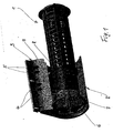
- Fig. 1 shows a perspective view of a dryer / filter cartridge 1, which is designed as a cage-like plastic insert and is substantially known from the aforementioned prior art.
- the dryer / filter cartridge 1 is arranged in a collector 2 partially shown, which is formed in this area as a profile piece and partially with an adjacent, parallel collecting tube 3 is integrated.
- Collecting tube 3 and collector 2 form two spaces through which a refrigerant flows, which chambers are connected to one another by overflow openings 4, 5.
- the manifold 3 communicates with pipes, not shown, of a capacitor, also not shown, which is preferably used for a motor vehicle air conditioning.
- the illustrated in the drawing hollow cylindrical part of the collector 2 is closed at the end by a sealing plug 6, which is fixed by a retaining ring 7 in the axial direction to the outside.
- a sealing plug is known from DE-A 100 39 260.
- the filter / dryer cartridge 1 has a circumferential, annular retaining rib 8, which rests on an annular stop 9 of the collector 2.
- FIG. 2 shows the dryer / filter cartridge 1 and the collector 2 according to FIG. 1 in a longitudinal section.
- collector 2 and manifold 3 are formed in this area as a one-piece profile piece, which (in the drawing) down in a tubular, dashed lines indicated collector 2 'and in a likewise shown in dashed collector tube 3' continues.
- the annular stop 9 is fixedly connected to the collector 2, z. B. formed in one piece or used as an additional part, and thus forms a support bearing for the annular retaining rib 8 of the dryer / filter cartridge 1.
- the interior of the cage-like sleeve of the dryer / filter cartridge 1 is filled with a dryer material, not shown in the form of granules and is after closed at the top by a first axially movable in the sleeve cover 10, on which a compression spring 11 is arranged.
- a second cover 12 is arranged, which is supported against a pin 6a of the sealing plug 6.
- the compressed compression spring 11 thus has the effect of compressing the granules, not shown, on the one hand via the cover 10 and, on the other hand, the plastic insert of the dryer / filter cartridge 1 via the retaining rib 3 against the stop 9 and the sealing plug 6 via the second cover 12 against the retaining ring 7 presses. This is fixed in its axial mobility and inward.
- the Abst Reifenproung consisting of retaining rib 8 and stop 9, can simultaneously perform sealing function, z. B. by between two annular surfaces 8, 9 a (not shown) is inserted seal.
Abstract
Description
Die Erfindung betrifft einen Kondensator, insbesondere für eine Kraftfahrzeug-Klimaanlage nach dem Oberbegriff des Patentanspruches 1 - bekannt durch die DE-A 103 06 192.The invention relates to a capacitor, in particular for a motor vehicle air conditioning system according to the preamble of claim 1 - known from DE-A 103 06 192.
Der durch die DE-A 103 06 192 bekannte Kondensator weist einen parallel zu einem Sammelrohr angeordneten Sammler auf, in welchem eine Filter- und/oder Trocknerpatrone angeordnet und durch eine ringförmige Halterippe in axialer Richtung im Sammler positioniert ist. Die Halterippe ist elastisch verformbar und in einer Ringnut des Sammlers gehalten, so dass Halterippe und Ringnut eine Schnapp- oder Rastverbindung bilden. Es kann dabei nicht ausgeschlossen werden, dass sich die bekannte Rastverbindung während der Montage oder während des Betriebs des Kondensators löst, so dass die Trockner- und/oder Filterpatrone nicht mehr im Sammler fixiert ist und ihre Funktion nicht ausüben kann. Der Betrieb der Klimaanlage kann dadurch beeinträchtigt werden. Der bekannte Sammler weist ein lösbares Verschlussteil auf, so dass die Trockner- und/oder Filterpatrone nach dem Löten des Kondensators montierbar und während des Betriebes aus Wartungsgründen austauschbar ist. Das Verschlussteil ist vorzugsweise als axial beweglicher Verschlussstopfen ausgebildet, welcher durch einen Sicherungsring in einer axialen Richtung (nach außen) festgelegt ist. Ein derartiger Verschlussstopfen wurde durch die DE-A 100 39 260 bekannt. Der Verschlussstopfen weist eine axiale Beweglichkeit nach innen auf, was zu Verkantungen des Verschlussstopfens im Sammler und damit möglichervueise zu Undichtigkeiten führen kann.The known from DE-A 103 06 192 capacitor has a collector arranged parallel to a collector, in which a filter and / or dryer cartridge is arranged and positioned by an annular retaining rib in the axial direction in the collector. The retaining rib is elastically deformable and held in an annular groove of the collector so that the retaining rib and the annular groove form a snap or latching connection. It can not be ruled out that the known locking connection dissolves during assembly or during operation of the capacitor, so that the dryer and / or filter cartridge is no longer fixed in the collector and can not perform their function. The operation of the air conditioner can be affected. The known collector has a releasable closure part, so that the dryer and / or filter cartridge after soldering of the capacitor mountable and interchangeable during operation for maintenance reasons. The closure member is preferably formed as an axially movable sealing plug, which is fixed by a retaining ring in an axial direction (outward). Such a sealing plug was known from DE-A 100 39 260. The sealing plug has an axial mobility inwards, resulting in tilting of the sealing plug in the collector and thus possibly lead to leaks.
Eine ähnliche Bauart für einen Kondensator mit integriertem Sammler wurde durch die DE-A 44 02 927 bekannt. Im Sammler ist eine Trockner/Filterpatrone angeordnet, welche in axialer Richtung einerseits durch Anschlag am Boden des Sammlers und andererseits durch Anschlag an einem Schraubdeckel fixiert ist. Darüber hinaus ist die Trockner/Filterpatrone über einen an der Patrone befestigten Dichtring und einen am Sammler angelöteten Ringsitz zwischen Überströmöffnungen abgedichtet, welche eine Verbindung zwischen Sammler und einem benachbarten Sammelrohr herstellen. Infolge der dreifachen Abstützung der Trockner/Filterpatrone im Sammler (oben, unten und in der Mitte) ist das System statisch unbestimmt.A similar design for a capacitor with integrated collector was known from DE-A 44 02 927. In the collector a dryer / filter cartridge is arranged, which is fixed in the axial direction on the one hand by abutment at the bottom of the collector and on the other hand by abutment against a screw cap. In addition, the dryer / filter cartridge is sealed by an attached to the cartridge sealing ring and a soldered to the collector ring seat between overflow, which establish a connection between the collector and an adjacent manifold. Due to the triple support of the dryer / filter cartridge in the collector (top, bottom and in the middle), the system is statically indefinite.
Es ist Aufgabe der vorliegenden Erfindung, die Fixierung und Abdichtung einer Trockner/Filterpatrone im Sammler eines Kondensators der eingangs genannten Art zu verbessern, insbesondere sicherer zu gestalten.It is an object of the present invention to improve the fixation and sealing of a dryer / filter cartridge in the collector of a capacitor of the type mentioned above, in particular to make it safer.
Diese Aufgabe wird durch die Merkmale des Patentanspruches 1 gelöst. Erfindungsgemäß ist im Sammler ein ringförmiger Anschlag vorgesehen, an welchem sich die ringförmige Halterippe der Trockner/Filterpatrone abstützt. In der entgegengesetzten Richtung ist die Trockner/Filterpatrone gegen das Verschlussteil abgestützt, so dass sie zwischen Verschlussteil und Anschlag am Sammler eingespannt ist. Damit ergibt sich eine eindeutige, betriebssichere Fixierung und auch eine einfache Montagemöglichkeit für die Trockner/Filterpatrone. Vorteilhafterweise ist zwischen Trockner/Filterpatrone und Verschlussteil eine Druckfeder angeordnet, welche gleichzeitig über einen beweglichen Deckel das in der Patrone befindliche Granulat zusammendrückt.This object is solved by the features of
Nach einer vorteilhaften Weiterbildung der Erfindung ist das Verschlussteil als axial beweglicher Versschlussstopfen ausgebildet, welcher über einen Sicherungsring in einer axialen Richtung, d. h. nach außen festgelegt ist, während er gleichzeitig in axialer Richtung nach innen beweglich ist. Der Verschlussstopfen wird durch die Druckfeder nach der Montage sofort gegen den Sicherungsring gedrückt und kann sich damit auch bei drucklosem Sammler bzw. Kondensator nicht in axialer Richtung bewegen. Dies bringt den Vorteil mit sich, dass der Verschlussstopfen nicht im Sammler verkanten und damit keine Undichtigkeit hervorrufen kann.According to an advantageous embodiment of the invention, the closure member is formed as an axially movable sealing plug, which is fixed via a retaining ring in an axial direction, ie outward, while at the same time in the axial direction is movable inwardly. The sealing plug is immediately counteracted by the pressure spring after assembly pressed the retaining ring and thus can not move in the axial direction even when unpressurized collector or condenser. This has the advantage that the plug does not tilt in the collector and thus can cause no leakage.
In weiterer vorteilhafter Ausgestaltung der Erfindung ist die ringförmige Halterippe gleichzeitig als Dichtmittel ausgebildet, z. B. durch Zwischenlage einer Flachdichtung. Damit kann eine zusätzliche umlaufende Dichtlippe - wie beim Stand der Technik - entfallen.In a further advantageous embodiment of the invention, the annular retaining rib is simultaneously formed as a sealant, for. B. by the interposition of a flat gasket. Thus, an additional circumferential sealing lip - as in the prior art - omitted.
Ein Ausführungsbeispiel der Erfindung ist in der Zeichnung dargestellt und wird im Folgenden näher beschrieben. Es zeigen
- Fig. 1 eine Trockner/Filterpatrone in einem teilweise dargestellten Sammler eines Kondensators in perspektivischer Darstellung und
- Fig. 2 die Trockner/Filterpatrone gemäß Fig. 1 in einem Längsschnitt.
- Fig. 1 shows a dryer / filter cartridge in a collector partially shown a capacitor in perspective view and
- Fig. 2, the dryer / filter cartridge of FIG. 1 in a longitudinal section.
Fig. 1 zeigt in perspektivischer Darstellung eine Trockner/Filterpatrone 1, welche als käfigartiger Kunststoffeinsatz ausgebildet und im Wesentlichen aus dem eingangs genannten Stand der Technik bekannt ist. Die Trockner/Filterpatrone 1 ist in einem teilweise dargestellten Sammler 2 angeordnet, welcher in diesem Bereich als Profilstück ausgebildet und teilweise mit einem benachbarten, parallel angeordneten Sammelrohr 3 integriert ist. Sammelrohr 3 und Sammler 2 bilden zwei von einem Kältemittel durchströmte Räume, welche durch Überströmöffnungen 4, 5 miteinander verbunden sind. Das Sammelrohr 3 kommuniziert mit nicht dargestellten Rohren eines ebenfalls nicht dargestellten Kondensators, welcher vorzugsweise für eine Kraftfahrzeug-Klimaanlage verwendbar ist. Der in der Zeichnung dargestellte hohlzylindrische Teil des Sammlers 2 ist stirnseitig durch einen Verschlussstopfen 6 verschlossen, welcher durch einen Sicherungsring 7 in axialer Richtung nach außen festgelegt ist. Ein derartiger Verschlussstopfen ist durch die DE-A 100 39 260 bekannt. Die Filter/Trocknerpatrone 1 weist eine umlaufende, ringförmige Halterippe 8 auf, welche auf einem ringförmigen Anschlag 9 des Sammlers 2 aufliegt.Fig. 1 shows a perspective view of a dryer /
Fig. 2 zeigt die Trockner/Filterpatrone 1 und den Sammler 2 gemäß Fig. 1 in einem Längsschnitt. Für gleiche Teile werden gleiche Bezugszahlen verwendet. Wie bereits erwähnt, sind Sammler 2 und Sammelrohr 3 in diesem Bereich als einstückiges Profilstück ausgebildet, welches sich (in der Zeichnung) nach unten in einem rohrförmigen, gestrichelt angedeuteten Sammler 2' und in einem ebenfalls gestrichelt dargestellten Sammelrohr 3' fortsetzt. Der ringförmige Anschlag 9 ist fest mit dem Sammler 2 verbunden, z. B. einstückig ausgebildet oder als zusätzliches Teil eingesetzt, und bildet somit ein Abstützlager für die ringförmige Halterippe 8 der Trockner/Filterpatrone 1. Das Innere der käfigartigen Hülse der Trockner/Filterpatrone 1 ist mit einem nicht dargestellten Trocknermaterial in Form eines Granulats gefüllt und wird nach oben durch einen ersten axial in der Hülse beweglichen Deckel 10 abgeschlossen, auf welchem eine Druckfeder 11 angeordnet ist. Über der Druckfeder 11 ist ein zweiter Deckel 12 angeordnet, welcher sich gegen einen Zapfen 6a des Verschlussstopfens 6 abstützt. Die komprimierte Druckfeder 11 hat somit die Wirkung, dass sie einerseits über den Deckel 10 das nicht dargestellte Granulat zusammendrückt und andererseits den Kunststoffeinsatz der Trockner/Filterpatrone 1 über die Halterippe 3 gegen den Anschlag 9 und den Verschlussstopfen 6 über den zweiten Deckel 12 gegen den Sicherungsring 7 drückt. Damit ist dieser in seiner axialen Beweglichkeit auch nach innen fixiert.FIG. 2 shows the dryer /
Die Abstützpaarung, bestehend aus Halterippe 8 und Anschlag 9, kann gleichzeitig Dichtfunktion übernehmen, z. B. indem zwischen beiden ringförmigen Flächen 8, 9 eine (nicht dargestellte) Dichtung eingelegt wird.The Abstützpaarung, consisting of retaining rib 8 and
Im Übrigen entspricht die Funktion der Trockner/Filterpatrone 1, des Sammlers 2 in Verbindung mit dem Sammelrohr 3 und dem gesamten Kältemittelkreislauf dem Stand der Technik, wie er beispielsweise in der DE-A 103 06 192 beschrieben ist, die hiermit voll umfänglich in den Offenbarungsgehalt dieser Anmeldung aufgenommen wird.Incidentally, the function of the dryer /
Claims (5)
Priority Applications (1)
| Application Number | Priority Date | Filing Date | Title |
|---|---|---|---|
| EP04292143A EP1643198A1 (en) | 2004-09-06 | 2004-09-06 | Condenser, in particular for a vehicle cooling system |
Applications Claiming Priority (1)
| Application Number | Priority Date | Filing Date | Title |
|---|---|---|---|
| EP04292143A EP1643198A1 (en) | 2004-09-06 | 2004-09-06 | Condenser, in particular for a vehicle cooling system |
Publications (1)
| Publication Number | Publication Date |
|---|---|
| EP1643198A1 true EP1643198A1 (en) | 2006-04-05 |
Family
ID=34931370
Family Applications (1)
| Application Number | Title | Priority Date | Filing Date |
|---|---|---|---|
| EP04292143A Ceased EP1643198A1 (en) | 2004-09-06 | 2004-09-06 | Condenser, in particular for a vehicle cooling system |
Country Status (1)
| Country | Link |
|---|---|
| EP (1) | EP1643198A1 (en) |
Citations (5)
| Publication number | Priority date | Publication date | Assignee | Title |
|---|---|---|---|---|
| EP0669506A1 (en) * | 1994-02-01 | 1995-08-30 | Behr GmbH & Co. | Condenser for an air conditioning equipment of a vehicle |
| JP2001041612A (en) * | 1999-07-23 | 2001-02-16 | Calsonic Kansei Corp | Liquid receiver |
| EP1147930A1 (en) * | 2000-03-24 | 2001-10-24 | Modine Manufacturing Company | Condenser for the airconditioning of a motor vehicle |
| DE10213176A1 (en) * | 2002-03-23 | 2003-10-02 | Behr Gmbh & Co | Kältmittelkondensator |
| EP1363086A1 (en) * | 2002-05-15 | 2003-11-19 | Sanden Corporation | Heat exchanger having an insert containing portion in which an insert is elastically supported |
-
2004
- 2004-09-06 EP EP04292143A patent/EP1643198A1/en not_active Ceased
Patent Citations (5)
| Publication number | Priority date | Publication date | Assignee | Title |
|---|---|---|---|---|
| EP0669506A1 (en) * | 1994-02-01 | 1995-08-30 | Behr GmbH & Co. | Condenser for an air conditioning equipment of a vehicle |
| JP2001041612A (en) * | 1999-07-23 | 2001-02-16 | Calsonic Kansei Corp | Liquid receiver |
| EP1147930A1 (en) * | 2000-03-24 | 2001-10-24 | Modine Manufacturing Company | Condenser for the airconditioning of a motor vehicle |
| DE10213176A1 (en) * | 2002-03-23 | 2003-10-02 | Behr Gmbh & Co | Kältmittelkondensator |
| EP1363086A1 (en) * | 2002-05-15 | 2003-11-19 | Sanden Corporation | Heat exchanger having an insert containing portion in which an insert is elastically supported |
Non-Patent Citations (1)
| Title |
|---|
| PATENT ABSTRACTS OF JAPAN vol. 2000, no. 19 5 June 2001 (2001-06-05) * |
Similar Documents
| Publication | Publication Date | Title |
|---|---|---|
| DE2922437C2 (en) | ||
| DE112005001062B4 (en) | Heat exchanger for a refrigeration cycle | |
| EP1461575B1 (en) | Soldered condenser | |
| EP3794256B1 (en) | Non-return valve, in particular for a refrigeration or heat circuit | |
| DE10213176A1 (en) | Kältmittelkondensator | |
| DE10039260B4 (en) | Closure for a collection container | |
| DE102005023103B4 (en) | Dryer for a cooling medium in a cooling medium circuit, in particular for an air conditioning system of a vehicle | |
| DE102005048772A1 (en) | Heat exchanger with integrated intermediate tank / dryer sleeve | |
| EP1682830A2 (en) | Heat exchanger and collector/drier unit for a heat exchanger | |
| EP4017770B1 (en) | Non-return valve device | |
| WO2003081148A1 (en) | Condenser | |
| EP1628106B1 (en) | Drier and filter cartridge for a receiver of a condenser, especially for a vehicle air conditioning system | |
| DE10306192A1 (en) | capacitor | |
| DE202009007149U1 (en) | Connecting part of a heating plate of a radiator and panel radiator | |
| DE3311816C1 (en) | Pressure relief valve for air brake systems of motor vehicles | |
| EP1436556A1 (en) | Refrigerant condenser | |
| EP1561077B1 (en) | Collecting tank, heat exchanger and refrigerant circuit | |
| EP1643198A1 (en) | Condenser, in particular for a vehicle cooling system | |
| EP1548348B1 (en) | Sealing arrangement, in particular for a pipe connection to an expansion element | |
| EP1420219B1 (en) | Condenser | |
| EP0049824A1 (en) | Pressure vessel, in particular accumulator for a fluid system | |
| WO2004020929A1 (en) | Refrigerant condenser, especially for motor vehicle air conditioning installations | |
| DE60012929T2 (en) | FILTER DEVICE | |
| DE3543206A1 (en) | Dryer container for air-conditioning and/or cooling installations | |
| DE102008058808A1 (en) | Heat exchanger assembly i.e. refrigerant condenser assembly, for motor vehicle air conditioning system, has connection formed by soldering for connection of separate tubular components of collector |
Legal Events
| Date | Code | Title | Description |
|---|---|---|---|
| PUAI | Public reference made under article 153(3) epc to a published international application that has entered the european phase |
Free format text: ORIGINAL CODE: 0009012 |
|
| AK | Designated contracting states |
Kind code of ref document: A1 Designated state(s): AT BE BG CH CY CZ DE DK EE ES FI FR GB GR HU IE IT LI LU MC NL PL PT RO SE SI SK TR |
|
| AX | Request for extension of the european patent |
Extension state: AL HR LT LV MK |
|
| 17P | Request for examination filed |
Effective date: 20061005 |
|
| AKX | Designation fees paid |
Designated state(s): AT BE BG CH CY CZ DE DK EE ES FI FR GB GR HU IE IT LI LU MC NL PL PT RO SE SI SK TR |
|
| AXX | Extension fees paid |
Extension state: MK Payment date: 20061005 Extension state: LV Payment date: 20061005 Extension state: LT Payment date: 20061005 Extension state: HR Payment date: 20061005 Extension state: AL Payment date: 20061005 |
|
| 17Q | First examination report despatched |
Effective date: 20071128 |
|
| STAA | Information on the status of an ep patent application or granted ep patent |
Free format text: STATUS: THE APPLICATION HAS BEEN REFUSED |
|
| 18R | Application refused |
Effective date: 20090813 |