EP1643198A1 - Condenseur, en particulier pour système de climatisation de véhicules - Google Patents
Condenseur, en particulier pour système de climatisation de véhicules Download PDFInfo
- Publication number
- EP1643198A1 EP1643198A1 EP04292143A EP04292143A EP1643198A1 EP 1643198 A1 EP1643198 A1 EP 1643198A1 EP 04292143 A EP04292143 A EP 04292143A EP 04292143 A EP04292143 A EP 04292143A EP 1643198 A1 EP1643198 A1 EP 1643198A1
- Authority
- EP
- European Patent Office
- Prior art keywords
- collector
- dryer
- filter cartridge
- closure part
- condenser
- Prior art date
- Legal status (The legal status is an assumption and is not a legal conclusion. Google has not performed a legal analysis and makes no representation as to the accuracy of the status listed.)
- Ceased
Links
Images

Classifications
-
- F—MECHANICAL ENGINEERING; LIGHTING; HEATING; WEAPONS; BLASTING
- F25—REFRIGERATION OR COOLING; COMBINED HEATING AND REFRIGERATION SYSTEMS; HEAT PUMP SYSTEMS; MANUFACTURE OR STORAGE OF ICE; LIQUEFACTION SOLIDIFICATION OF GASES
- F25B—REFRIGERATION MACHINES, PLANTS OR SYSTEMS; COMBINED HEATING AND REFRIGERATION SYSTEMS; HEAT PUMP SYSTEMS
- F25B39/00—Evaporators; Condensers
- F25B39/04—Condensers
-
- F—MECHANICAL ENGINEERING; LIGHTING; HEATING; WEAPONS; BLASTING
- F25—REFRIGERATION OR COOLING; COMBINED HEATING AND REFRIGERATION SYSTEMS; HEAT PUMP SYSTEMS; MANUFACTURE OR STORAGE OF ICE; LIQUEFACTION SOLIDIFICATION OF GASES
- F25B—REFRIGERATION MACHINES, PLANTS OR SYSTEMS; COMBINED HEATING AND REFRIGERATION SYSTEMS; HEAT PUMP SYSTEMS
- F25B2339/00—Details of evaporators; Details of condensers
- F25B2339/04—Details of condensers
- F25B2339/044—Condensers with an integrated receiver
- F25B2339/0441—Condensers with an integrated receiver containing a drier or a filter
Definitions
- the invention relates to a capacitor, in particular for a motor vehicle air conditioning system according to the preamble of claim 1 - known from DE-A 103 06 192.
- the known from DE-A 103 06 192 capacitor has a collector arranged parallel to a collector, in which a filter and / or dryer cartridge is arranged and positioned by an annular retaining rib in the axial direction in the collector.
- the retaining rib is elastically deformable and held in an annular groove of the collector so that the retaining rib and the annular groove form a snap or latching connection. It can not be ruled out that the known locking connection dissolves during assembly or during operation of the capacitor, so that the dryer and / or filter cartridge is no longer fixed in the collector and can not perform their function. The operation of the air conditioner can be affected.
- the known collector has a releasable closure part, so that the dryer and / or filter cartridge after soldering of the capacitor mountable and interchangeable during operation for maintenance reasons.
- the closure member is preferably formed as an axially movable sealing plug, which is fixed by a retaining ring in an axial direction (outward).
- a sealing plug was known from DE-A 100 39 260.
- the sealing plug has an axial mobility inwards, resulting in tilting of the sealing plug in the collector and thus possibly lead to leaks.
- a similar design for a capacitor with integrated collector was known from DE-A 44 02 927.
- a dryer / filter cartridge is arranged, which is fixed in the axial direction on the one hand by abutment at the bottom of the collector and on the other hand by abutment against a screw cap.
- the dryer / filter cartridge is sealed by an attached to the cartridge sealing ring and a soldered to the collector ring seat between overflow, which establish a connection between the collector and an adjacent manifold. Due to the triple support of the dryer / filter cartridge in the collector (top, bottom and in the middle), the system is statically indefinite.
- an annular stop is provided in the collector, on which the annular retaining rib of the dryer / filter cartridge is supported.
- the dryer / filter cartridge is supported against the closure member, so that it is clamped between the closure part and stop on the collector.
- a compression spring is arranged between the dryer / filter cartridge and the closure part, which at the same time compresses the granules in the cartridge via a movable cover.
- the closure member is formed as an axially movable sealing plug, which is fixed via a retaining ring in an axial direction, ie outward, while at the same time in the axial direction is movable inwardly.
- the sealing plug is immediately counteracted by the pressure spring after assembly pressed the retaining ring and thus can not move in the axial direction even when unpressurized collector or condenser. This has the advantage that the plug does not tilt in the collector and thus can cause no leakage.
- the annular retaining rib is simultaneously formed as a sealant, for. B. by the interposition of a flat gasket.
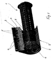
- Fig. 1 shows a perspective view of a dryer / filter cartridge 1, which is designed as a cage-like plastic insert and is substantially known from the aforementioned prior art.
- the dryer / filter cartridge 1 is arranged in a collector 2 partially shown, which is formed in this area as a profile piece and partially with an adjacent, parallel collecting tube 3 is integrated.
- Collecting tube 3 and collector 2 form two spaces through which a refrigerant flows, which chambers are connected to one another by overflow openings 4, 5.
- the manifold 3 communicates with pipes, not shown, of a capacitor, also not shown, which is preferably used for a motor vehicle air conditioning.
- the illustrated in the drawing hollow cylindrical part of the collector 2 is closed at the end by a sealing plug 6, which is fixed by a retaining ring 7 in the axial direction to the outside.
- a sealing plug is known from DE-A 100 39 260.
- the filter / dryer cartridge 1 has a circumferential, annular retaining rib 8, which rests on an annular stop 9 of the collector 2.
- FIG. 2 shows the dryer / filter cartridge 1 and the collector 2 according to FIG. 1 in a longitudinal section.
- collector 2 and manifold 3 are formed in this area as a one-piece profile piece, which (in the drawing) down in a tubular, dashed lines indicated collector 2 'and in a likewise shown in dashed collector tube 3' continues.
- the annular stop 9 is fixedly connected to the collector 2, z. B. formed in one piece or used as an additional part, and thus forms a support bearing for the annular retaining rib 8 of the dryer / filter cartridge 1.
- the interior of the cage-like sleeve of the dryer / filter cartridge 1 is filled with a dryer material, not shown in the form of granules and is after closed at the top by a first axially movable in the sleeve cover 10, on which a compression spring 11 is arranged.
- a second cover 12 is arranged, which is supported against a pin 6a of the sealing plug 6.
- the compressed compression spring 11 thus has the effect of compressing the granules, not shown, on the one hand via the cover 10 and, on the other hand, the plastic insert of the dryer / filter cartridge 1 via the retaining rib 3 against the stop 9 and the sealing plug 6 via the second cover 12 against the retaining ring 7 presses. This is fixed in its axial mobility and inward.
- the Abst Reifenproung consisting of retaining rib 8 and stop 9, can simultaneously perform sealing function, z. B. by between two annular surfaces 8, 9 a (not shown) is inserted seal.
Priority Applications (1)
| Application Number | Priority Date | Filing Date | Title |
|---|---|---|---|
| EP04292143A EP1643198A1 (fr) | 2004-09-06 | 2004-09-06 | Condenseur, en particulier pour système de climatisation de véhicules |
Applications Claiming Priority (1)
| Application Number | Priority Date | Filing Date | Title |
|---|---|---|---|
| EP04292143A EP1643198A1 (fr) | 2004-09-06 | 2004-09-06 | Condenseur, en particulier pour système de climatisation de véhicules |
Publications (1)
| Publication Number | Publication Date |
|---|---|
| EP1643198A1 true EP1643198A1 (fr) | 2006-04-05 |
Family
ID=34931370
Family Applications (1)
| Application Number | Title | Priority Date | Filing Date |
|---|---|---|---|
| EP04292143A Ceased EP1643198A1 (fr) | 2004-09-06 | 2004-09-06 | Condenseur, en particulier pour système de climatisation de véhicules |
Country Status (1)
| Country | Link |
|---|---|
| EP (1) | EP1643198A1 (fr) |
Citations (5)
| Publication number | Priority date | Publication date | Assignee | Title |
|---|---|---|---|---|
| EP0669506A1 (fr) * | 1994-02-01 | 1995-08-30 | Behr GmbH & Co. | Condenseur pour une installation de climatisation d'un véhicule |
| JP2001041612A (ja) * | 1999-07-23 | 2001-02-16 | Calsonic Kansei Corp | 受液器 |
| EP1147930A1 (fr) * | 2000-03-24 | 2001-10-24 | Modine Manufacturing Company | Condenseur pour la climatisation de véhicule automobile |
| DE10213176A1 (de) * | 2002-03-23 | 2003-10-02 | Behr Gmbh & Co | Kältmittelkondensator |
| EP1363086A1 (fr) * | 2002-05-15 | 2003-11-19 | Sanden Corporation | Echangeur de chaleur avec une partie pour contenir une pièce rapportée laquelle y est supportée élastiquement |
-
2004
- 2004-09-06 EP EP04292143A patent/EP1643198A1/fr not_active Ceased
Patent Citations (5)
| Publication number | Priority date | Publication date | Assignee | Title |
|---|---|---|---|---|
| EP0669506A1 (fr) * | 1994-02-01 | 1995-08-30 | Behr GmbH & Co. | Condenseur pour une installation de climatisation d'un véhicule |
| JP2001041612A (ja) * | 1999-07-23 | 2001-02-16 | Calsonic Kansei Corp | 受液器 |
| EP1147930A1 (fr) * | 2000-03-24 | 2001-10-24 | Modine Manufacturing Company | Condenseur pour la climatisation de véhicule automobile |
| DE10213176A1 (de) * | 2002-03-23 | 2003-10-02 | Behr Gmbh & Co | Kältmittelkondensator |
| EP1363086A1 (fr) * | 2002-05-15 | 2003-11-19 | Sanden Corporation | Echangeur de chaleur avec une partie pour contenir une pièce rapportée laquelle y est supportée élastiquement |
Non-Patent Citations (1)
| Title |
|---|
| PATENT ABSTRACTS OF JAPAN vol. 2000, no. 19 5 June 2001 (2001-06-05) * |
Similar Documents
| Publication | Publication Date | Title |
|---|---|---|
| DE2922437C2 (fr) | ||
| DE112005001062B4 (de) | Wärmetauscher für einen Kältekreislauf | |
| EP1461575B1 (fr) | Condensateur soude | |
| EP3794256B1 (fr) | Soupape de retour, en particulier pour un circuit de refroidissement ou de chauffage | |
| DE10213176A1 (de) | Kältmittelkondensator | |
| DE102004050409A1 (de) | Akkumulator mit internem Wärmetauscher für eine Klimaanlage | |
| DE10039260B4 (de) | Verschluß für einen Sammelbehälter | |
| DE102005023103B4 (de) | Trockner für ein Kühlmedium in einem Kühlmedienkreislauf, insbesondere für eine Klimaanlage eines Fahrzeugs | |
| DE102005048772A1 (de) | Wärmetauscher mit integrierter Zwischenbehälter/Trockner-Hülse | |
| WO2005050119A2 (fr) | Echangeur thermique et ensemble collecteur-dessiccateur pour echangeur thermique | |
| EP4017770B1 (fr) | Dispositif de clapet antiretour | |
| WO2003081148A1 (fr) | Condenseur | |
| EP1628106B1 (fr) | Cartouche de sécheur et filtre pour un accumulateur d'un condenseur, en particulier pour un système de réfrigération d'un véhicule automobile | |
| DE10306192A1 (de) | Kondensator | |
| DE202009007149U1 (de) | Anschlussteil einer Heizplatte eines Heizkörpers sowie Plattenheizkörper | |
| DE3311816C1 (de) | Druckbegrenzungsventil fuer Druckluftbremsanlagen von Kraftfahrzeugen | |
| EP1436556A1 (fr) | Condenseur a agent refrigerant | |
| EP1561077B1 (fr) | Reservoir collecteur, echangeur thermique et circuit de fluide réfrigérant | |
| EP1643198A1 (fr) | Condenseur, en particulier pour système de climatisation de véhicules | |
| EP1548348B1 (fr) | Dispositif d'étanchéité, en particulier pour le raccordement d'un tuyau à un organe d'expansion | |
| EP1420219B1 (fr) | Condensateur | |
| EP0049824A1 (fr) | Réservoir de pression, en particulier accumulateur pour une installation à fluide | |
| DE60012929T2 (de) | Filtervorrichtung | |
| DE3543206A1 (de) | Trocknerbehaelter fuer klima- und/oder kuehlanlagen | |
| DE102008058808A1 (de) | Wärmeübertragerbaugruppe |
Legal Events
| Date | Code | Title | Description |
|---|---|---|---|
| PUAI | Public reference made under article 153(3) epc to a published international application that has entered the european phase |
Free format text: ORIGINAL CODE: 0009012 |
|
| AK | Designated contracting states |
Kind code of ref document: A1 Designated state(s): AT BE BG CH CY CZ DE DK EE ES FI FR GB GR HU IE IT LI LU MC NL PL PT RO SE SI SK TR |
|
| AX | Request for extension of the european patent |
Extension state: AL HR LT LV MK |
|
| 17P | Request for examination filed |
Effective date: 20061005 |
|
| AKX | Designation fees paid |
Designated state(s): AT BE BG CH CY CZ DE DK EE ES FI FR GB GR HU IE IT LI LU MC NL PL PT RO SE SI SK TR |
|
| AXX | Extension fees paid |
Extension state: MK Payment date: 20061005 Extension state: LV Payment date: 20061005 Extension state: LT Payment date: 20061005 Extension state: HR Payment date: 20061005 Extension state: AL Payment date: 20061005 |
|
| 17Q | First examination report despatched |
Effective date: 20071128 |
|
| STAA | Information on the status of an ep patent application or granted ep patent |
Free format text: STATUS: THE APPLICATION HAS BEEN REFUSED |
|
| 18R | Application refused |
Effective date: 20090813 |