EP4017770B1 - Dispositif de clapet antiretour - Google Patents
Dispositif de clapet antiretour Download PDFInfo
- Publication number
- EP4017770B1 EP4017770B1 EP20754200.2A EP20754200A EP4017770B1 EP 4017770 B1 EP4017770 B1 EP 4017770B1 EP 20754200 A EP20754200 A EP 20754200A EP 4017770 B1 EP4017770 B1 EP 4017770B1
- Authority
- EP
- European Patent Office
- Prior art keywords
- sealing element
- flow channel
- openings
- flow
- fluid flow
- Prior art date
- Legal status (The legal status is an assumption and is not a legal conclusion. Google has not performed a legal analysis and makes no representation as to the accuracy of the status listed.)
- Active
Links
- 238000007789 sealing Methods 0.000 claims description 138
- 239000012530 fluid Substances 0.000 claims description 46
- 238000012545 processing Methods 0.000 claims description 17
- 238000002360 preparation method Methods 0.000 description 27
- 239000002184 metal Substances 0.000 description 9
- 238000004581 coalescence Methods 0.000 description 6
- 238000011045 prefiltration Methods 0.000 description 6
- 230000000295 complement effect Effects 0.000 description 5
- 239000002274 desiccant Substances 0.000 description 5
- 239000002245 particle Substances 0.000 description 5
- 230000000903 blocking effect Effects 0.000 description 3
- 230000008929 regeneration Effects 0.000 description 3
- 238000011069 regeneration method Methods 0.000 description 3
- 238000007906 compression Methods 0.000 description 2
- 230000006835 compression Effects 0.000 description 1
- 230000001419 dependent effect Effects 0.000 description 1
- 238000013461 design Methods 0.000 description 1
- 238000001035 drying Methods 0.000 description 1
- 229920001971 elastomer Polymers 0.000 description 1
- 239000000806 elastomer Substances 0.000 description 1
- 210000003746 feather Anatomy 0.000 description 1
- 239000000463 material Substances 0.000 description 1
- 238000012986 modification Methods 0.000 description 1
- 230000004048 modification Effects 0.000 description 1
- 238000012856 packing Methods 0.000 description 1
- 239000004071 soot Substances 0.000 description 1
- 239000000725 suspension Substances 0.000 description 1
- 230000008961 swelling Effects 0.000 description 1
- 230000007704 transition Effects 0.000 description 1
- 238000013022 venting Methods 0.000 description 1
Images

Classifications
-
- B—PERFORMING OPERATIONS; TRANSPORTING
- B60—VEHICLES IN GENERAL
- B60T—VEHICLE BRAKE CONTROL SYSTEMS OR PARTS THEREOF; BRAKE CONTROL SYSTEMS OR PARTS THEREOF, IN GENERAL; ARRANGEMENT OF BRAKING ELEMENTS ON VEHICLES IN GENERAL; PORTABLE DEVICES FOR PREVENTING UNWANTED MOVEMENT OF VEHICLES; VEHICLE MODIFICATIONS TO FACILITATE COOLING OF BRAKES
- B60T17/00—Component parts, details, or accessories of power brake systems not covered by groups B60T8/00, B60T13/00 or B60T15/00, or presenting other characteristic features
- B60T17/04—Arrangements of piping, valves in the piping, e.g. cut-off valves, couplings or air hoses
-
- B—PERFORMING OPERATIONS; TRANSPORTING
- B60—VEHICLES IN GENERAL
- B60T—VEHICLE BRAKE CONTROL SYSTEMS OR PARTS THEREOF; BRAKE CONTROL SYSTEMS OR PARTS THEREOF, IN GENERAL; ARRANGEMENT OF BRAKING ELEMENTS ON VEHICLES IN GENERAL; PORTABLE DEVICES FOR PREVENTING UNWANTED MOVEMENT OF VEHICLES; VEHICLE MODIFICATIONS TO FACILITATE COOLING OF BRAKES
- B60T15/00—Construction arrangement, or operation of valves incorporated in power brake systems and not covered by groups B60T11/00 or B60T13/00
- B60T15/02—Application and release valves
- B60T15/36—Other control devices or valves characterised by definite functions
-
- B—PERFORMING OPERATIONS; TRANSPORTING
- B60—VEHICLES IN GENERAL
- B60T—VEHICLE BRAKE CONTROL SYSTEMS OR PARTS THEREOF; BRAKE CONTROL SYSTEMS OR PARTS THEREOF, IN GENERAL; ARRANGEMENT OF BRAKING ELEMENTS ON VEHICLES IN GENERAL; PORTABLE DEVICES FOR PREVENTING UNWANTED MOVEMENT OF VEHICLES; VEHICLE MODIFICATIONS TO FACILITATE COOLING OF BRAKES
- B60T17/00—Component parts, details, or accessories of power brake systems not covered by groups B60T8/00, B60T13/00 or B60T15/00, or presenting other characteristic features
- B60T17/002—Air treatment devices
- B60T17/004—Draining and drying devices
-
- B—PERFORMING OPERATIONS; TRANSPORTING
- B60—VEHICLES IN GENERAL
- B60Y—INDEXING SCHEME RELATING TO ASPECTS CROSS-CUTTING VEHICLE TECHNOLOGY
- B60Y2410/00—Constructional features of vehicle sub-units
- B60Y2410/104—Hydraulic valves
-
- B—PERFORMING OPERATIONS; TRANSPORTING
- B60—VEHICLES IN GENERAL
- B60Y—INDEXING SCHEME RELATING TO ASPECTS CROSS-CUTTING VEHICLE TECHNOLOGY
- B60Y2410/00—Constructional features of vehicle sub-units
- B60Y2410/105—Valve bodies; Mounting of hydraulic controllers
Definitions
- the present invention relates to a check valve device which is particularly suitable for fluid preparation in commercial vehicles.
- Such a check valve device can be used in a device for fluid preparation, such as an air dryer cartridge in commercial vehicles such as trucks and tractors. These often have one or more compressed air consumers such as brake systems or air suspensions that need to be supplied with compressed air.
- the compressed air is typically provided by a compressor, for example a reciprocating compressor driven by a drive motor of the vehicle.
- the compressed air provided by the compressor usually has to be further processed.
- the compressed air treatment systems provided for this purpose the compressed air is cleaned of dirt particles that were already contained in the sucked-in air, as well as oil and soot particles that are introduced into the compressed air by the compressor during the compression process, and any moisture present in the compressed air is separated.
- the compressed air treatment systems of commercial vehicles usually have air dryer cartridges that can dehumidify the compressed air and preferably also absorb oil and dirt particles.
- Conventional air dryer cartridges such as those found in the DE 10 2010 010882 A1 , DE 10 2007 011246 A1 , D3 DE 103 29 401 A1 and EP 1 669125 A1 are described, have a cartridge housing with a closed housing cover, a desiccant accommodated in the cartridge housing, a fastening flange for closing an open end face of the cartridge housing facing away from the housing cover and fastening the air dryer cartridge to a compressed air treatment system and a filter device arranged within the cartridge housing, such as a coalescence filter, to clean the compressed air.
- the compressed air first flows through the filter device before it reaches the desiccant.
- a bypass channel is generally provided to bypass the filter device and a check valve is arranged as a bypass of the filter device.
- the bypass channel is used to blow off oil that has coalesced on the filter device during a venting stroke.
- Conventional bypass devices include check valves, which are typically formed from an elastomer. These are expensive and their assembly is complex.
- the invention is based on the object of creating an improved check valve device that can be easily assembled.
- the check valve device has at least a first part of a flow channel for a fluid and a movable, in particular cord-shaped, sealing element arranged in the flow channel, which is configured so that it can be moved at least partially between a closed position and an open position, wherein in the open position fluid flow is permitted through the flow channel, while in the closed position the fluid flow through the flow channel is blocked by positive connection with the sealing element.
- the device according to the invention has the advantage that the particularly cord-shaped sealing element is set up in such a way that it can be moved or offset at least in sections between the closed position and the open position in the flow channel or can also be moved by deformation, so that the function of the sealing element attachment to the flow channel is not necessary.
- the sealing element can be constructed very simply and without fasteners.
- the structure of the sealing element can be very space-saving.
- the device according to the invention can be used, for example, in devices for processing fluids, such as air, in particular compressed air, or gas, such as in air dryer cartridges. It is also conceivable to use it in hydraulic or pneumatic devices for vehicles, especially commercial vehicles, in which devices that function on the principle of a check valve can be used.
- the device further has a housing and a fluid processing device arranged in the housing and positioned in a flow path of the fluid, the flow channel forming a bypass for the flow path.
- the device can be used, for example, in an air dryer cartridge.
- the second part of the flow channel can be arranged complementary to the first part of the flow channel and also part of the device or on another part, such as a fluid processing system of a commercial vehicle, or form a part thereof.
- the sealing element is positively connected to the device for fluid preparation and held thereon.
- This has the advantage that the sealing element does not have to be specially attached to the device compared to conventional check valves. The assembly or replacement of the sealing element can therefore be carried out easily.
- the sealing element can be easily manufactured since it does not need to have any elements for its attachment to the device. It is conceivable, for example, to arrange an annular sealing element along a flow channel that is also annular, the sealing element being designed with an oversize or larger circumference than that of the Flow channel, so that it is held on the flow channel surrounding the sealing element and seals it due to the excess or larger circumference.
- annular sealing element that surrounds an annular flow channel and is held on this due to an undersize or smaller circumference of the sealing element than that of the flow channel and seals it.
- flow channel it would be conceivable to design it in the form of several openings or sections arranged in a ring.
- the sealing element is an O-ring or a section thereof.
- an O-ring as a sealing element is that it can be produced inexpensively as a mass-produced product.
- the O-ring can be inserted into the device without the need to fix it in the device.
- the O-ring can be installed without special tools.
- a support part of the device for the O-ring can be designed in a simplified manner without a special fixing geometry. By using a suitable counter contour for the O-ring, the maximum possible swelling of the O-ring can be compensated for and a cheaper O-ring material can therefore be used.
- the flow channel can have a shape that is complementary to the sealing element or O-ring, in particular also be annular.
- the sealing element can be held on the flow channel by an oversize, so that the flow channel is sealed without being acted upon by a fluid.
- This structure is particularly suitable for a device in which an annular flow channel surrounds the annular sealing element.
- the O-ring could also surround an annular flow channel and seal against it due to its smaller circumference be held.
- the sealing element has an elongated shape, a rod or tube shape with a round, square, oval or elliptical cross section.
- the sealing element is movably arranged between two surfaces, a first of which is part of or forms at least part of the bypass channel.
- the fluid flow through the bypass channel can be blocked by means of a positive connection between the sealing element and at least one of the surfaces.
- the other surface can be or form a further part of at least part of the bypass channel and can be arranged opposite the first.
- One or both surfaces can be structured and have one or more edges, ridges or depressions.
- one of the surfaces can have the shape of a groove, which is formed by at least two edges and a surface, in particular be designed as an annular groove or a part thereof.
- the other, second surface can also be part of the compressed air preparation device, but can also be part of a further device, such as a compressed air preparation system, to which the compressed air preparation device is connected for compressed air preparation.
- the fluid processing device has a cylindrical shape, such as a cartridge, in particular an air dryer cartridge.
- a cylindrical shape such as a cartridge, in particular an air dryer cartridge.
- Other shapes such as a cubic or cuboid shape are also conceivable.
- the distance between the two surfaces along the direction of movement of the sealing element corresponds in sections to the height or the diameter of the sealing element, is greater or less than the height or the diameter of the sealing element or changes along the direction of movement of the sealing element according to a combination of two or more sections with one or more of the above-mentioned distances.
- the distance between the two surfaces along the direction of movement of the sealing element is at least in a section greater than the height or the diameter of the sealing element, so that a fluid flow between at least one of the two surfaces and the sealing element can flow past the sealing element when the sealing element positioned in this section.
- one or more contact surfaces or sealing edges through which the movement of the sealing element is limited, extend between the surfaces at an angle or perpendicular to the direction of movement of the sealing element. Between the one or more contact surfaces or sealing edges, the sealing element can seal or block the flow channel in a form-fitting manner when it rests against it. If necessary, the sealing element is deformed, in particular compressed.
- one or more openings for the passage of fluid flow are arranged in a wall extending at an angle or perpendicularly between the surfaces, wherein fluid flow is blocked by the sealing element when the sealing element closes the one or more openings.
- one or more openings or depressions are formed in one or both surfaces.
- the flow channel of the device has one or more openings for the passage of the fluid flow, wherein when the sealing element is positioned at one of the openings of the one or more openings of the flow channel, these are closed by the sealing element and the fluid flow is blocked through the flow channel is.
- the flow channel of the device has one or more openings for the passage of the fluid flow, wherein after movement between the surfaces and over one of the openings of the one or more openings of the flow channel in one of the surfaces or edges, the sealing element is so im Flow channel is positioned so that the fluid flow through the flow channel is blocked.
- the flow channel of the device has one or more openings for the passage of the fluid flow, wherein after movement between the surfaces and over one of the openings of the one or more openings of the flow channel in one of the surfaces, the sealing element is thus in the flow channel is positioned so that the fluid flow is permitted through the flow channel.
- the device has two surfaces arranged concentrically to a longitudinal axis of the device, which are perpendicular or inclined in relation to the longitudinal axis of the device and wherein a plurality of ring-shaped openings are formed in at least one of the surfaces, wherein in the closed position of the Sealing element a fluid flow through at least one of the openings is blocked by an annular sealing element arranged between the surfaces, which surrounds the annularly arranged openings, and in the open position of the sealing element a fluid flow is permitted through at least one of the openings by the annular sealing element being so arranged that at least a portion of the sealing element is located between the at least one opening and the longitudinal axis of the device.
- annular gap or an annular groove could also be used, in which the sealing element is arranged.
- annular gaps or grooves one or more annular surfaces, gaps or grooves are also conceivable, which only extend over an angular range such as 10°, 25°, 45° and multiples thereof.
- the sealing element can be moved from the open position to the closed position or from the closed position to the open position by means of a fluid.
- the sealing element can be moved from the closed position to the open position or from the open position to the closed position by its elasticity.
- a first part of the flow channel for bypassing the fluid processing device is formed by a part of a filter, filter housing or a fluid processing device.
- This part can be put together with a complementary part of the flow channel, which can also be part of the device for fluid processing or also by another component, such as a fluid processing system of a commercial vehicle, in order to form the flow channel for the fluid flow.
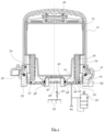
- FIG. 1 shows the structure of a device 10 for compressed air preparation according to a first exemplary embodiment.
- the device 10 for processing compressed air comprises a housing 12 with a substantially cylindrical wall section.
- a dry insert 14 is arranged in the housing 12 and contains a desiccant (not shown).
- a compressed air processing component 18 such as a coalescence filter, which extends over the entire circumference of the device 10 for compressed air processing.
- a bypass channel 26 in which a sealing element 27 in the form of an O-ring 2 is arranged, which blocks a path from the pre-filter area 22 to the post-filter area 24 along a metal plate 32 provided with through openings 38 and depending on the pressure conditions the flow in the opposite direction is allowed.
- the bypass channel 26 extends between the underside of the coalescence filter and the metal plate 32.
- the O-ring is inserted into the device 10 for compressed air preparation without the need for special fixation in the device 10.
- the O-ring can be installed without special tools.
- a carrier part of the device 10 for preparing compressed air for the O-ring can be designed in a simplified manner without a special fixing geometry.
- the carrier part is formed by an outer sealing edge 68 on which the O-ring is held in a form-fitting manner.
- the dry insert 14 is limited at the bottom by a secondary filter 40 and an apertured plate 32 underneath.
- a drain safety valve 30 belonging to a pressure regulator is installed in the periphery of the device 10 for compressed air preparation or integrated with it. This is connected in parallel to a compressed air supply 44 at the entrance 46 of the device 10 for compressed air preparation.
- Compressed air consumers such as the four brake circuits 52 indicated here, are connected to an output 48 of the device 10 for preparing compressed air via a check valve 50.
- the dry insert 14 is subjected to force from above by a spring 36 in order to ensure a tight packing of the desiccant in the dry insert 14.
- Various seals 54, 56, 58 are provided, with the seal 58, for example, sealing the inlet 46 and the outlet 48 against one another.
- the device 10 for compressed air preparation is connected to an in Fig. 1 indicated air treatment system 53 connected.
- the device 10 for processing compressed air can also be connected to the air processing system 53 via a thread.
- compressed air is delivered from the compressed air supply 44 to the input 46.
- This compressed air flows through through openings 38 in the metal plate into the pre-filter area 22 and subsequently through the coalescence filter into the post-filter area 24.
- Foreign particles are filtered out by the coalescence filter and accumulate at the bottom of the post-filter area 24 and in the bypass channel 26.
- the air continues to flow upwards along the wall of the housing 12 and then from above into the drying insert 14 in order to flow through the desiccant and be dried in it.
- the air then flows through the secondary filter 40 and the plate 42 provided with openings in the direction of the outlet 48, from where it flows via the check valve 50 to the consumers, that is to say in particular to the brake circuits 52.
- the sealing element 27 formed by the O-ring is pressurized by the air and blocks the bypass channel 26 by means of a positive connection with the sealing edge 68 and the bottom or the metal plate 32 of the bypass channel 26.
- the drain safety valve 30 belonging to the pressure regulator now opens, the pressure in the pre-filter area 22 collapses. There is therefore a significantly higher pressure in the post-filter area 24 than in the pre-filter area 22, so that the O-ring that positively locks the bypass channel 26 is pressed radially inwards, towards an inner sealing edge 70 of the bypass channel 26.
- the bypass channel 26 is opened by a translational movement of at least part of the O-ring 27 and a transport of the accumulated foreign particles from the post-filter area 24 into the pre-filter area 22 and subsequently via the drain safety valve 30 to the outside of the air treatment system 53 is permitted.
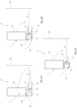
- FIGS 2a-2c schematically show two embodiments of a device 10 for compressed air treatment with an air treatment component 18, such as one or more filters.
- the device 10 shown for compressed air preparation has a bypass channel 26 with a therein arranged sealing element 27.
- the bypass channel 26 is formed at least in sections by the underside of the air treatment component 18 and a metal plate 32 opposite this on the underside of the device 10 for compressed air preparation.
- the sealing element 27 is formed by an O-ring which extends in a circular symmetrical manner in an annular groove 64 together with this around a longitudinal axis 66 of the device 10 for compressed air preparation.
- the O-ring and the annular groove 64 are shown in cross section and both extend perpendicular to the plane of the image. Both the O-ring and the annular groove 64 are only shown on one side of the device and can, however, extend in a circle up to over 360°, forming closed rings. However, it is also conceivable to configure both the annular groove 64 and the O-ring so that they only extend over a sector of a circle, such as 5°, 25°, 45° or a multiple thereof.
- a linear or rectilinear groove 64 and a corresponding sealing element 27 arranged therein are also conceivable.
- the annular groove 64 which is open downwards in the embodiment shown, is delimited by an outer sealing edge 68 and an inner sealing edge 70.
- the outer sealing edge 68 has a height that is less than half the maximum height of the in the Figure 2A Bypass channel 26 shown and also less than half the height of the O-ring, while the inner sealing edge 70 has a height that is greater than half the maximum height of the in the Figure 2A bypass channel 26 shown and is also greater than half the height of the O-ring.
- the O-ring has an outer radius R which approximately corresponds to or is slightly larger than that of the outer edge of the annular groove 64 and the outer sealing edge 68, so that the O-ring can be attached to the outer sealing edge 68 of the bypass without being subjected to compressed air.
- Channel 26 and the bottom of the bypass channel 26 rests in a form-fitting manner. Due to the positive fit, the O-ring is held on the device 10 for compressed air preparation, in particular on its outer sealing edge 68.
- the radius of the O-ring can also be selected so that the O-ring experiences compression even without exposure to compressed air.
- the outer radius of the O-ring can be chosen to be 2%, 5%, 10% or 15% larger than the outer radius of the annular groove 64.
- the O-ring in positive engagement with the outer sealing edge 68 and the lower surface of the bypass channel 26 blocks the passage of compressed air from the side of the inner sealing edge 70, which is between the lower end of the same and the lower surface in the Bypass channel 26 passes and the O-ring is pressurized in the blocking direction, while at the same time the compressed air flows through the air treatment component 18.
- the O-ring can also be reversibly deformed by the compressed air, depending on the strength of the pressure. This corresponds to the normal operation of the device 10 for compressed air preparation.
- the O-ring has an inner radius that corresponds to that of the inner sealing edge 70 or is even slightly smaller than this, such as 2%, 5%, 10% or 15%, so that the O-ring is held on the inner sealing edge 70 without the application of compressed air and blocks it in positive connection with the inner sealing edge 70 and the underside of the bypass channel 26.
- Such an arrangement can be particularly useful for embodiments in which, during normal operation, the O-ring is subjected to compressed air in the blocking direction from the side of the outer sealing edge 68 and is thereby additionally pressed against the inner sealing edge 70 and the underside of the bypass channel 26 is while the air treatment component 18 is flowed through by the compressed air, and on the other hand in the regeneration mode when compressed air is applied from the side of the inner sealing edge 70, the O-ring is pushed away from the inner sealing edge 70 and compressed air bypassing the air treatment component 18 through the bypass channel 26 flows.
- Figure 2B is the device according to the same embodiment as in Fig. 2A shown, however, the position of the sealing element 27 is offset from the outer sealing edge 68 in accordance with the regeneration operation of the device 10 for air treatment, since the O-ring in the bypass channel 26 is pressurized with compressed air, bypassing the air treatment component 18, so that the positive connection between the bypass channel 26 and the O-ring is loosened, the bypass channel 26 is open and compressed air between the O-ring and the lower surface and possibly also between the O-ring and the upper surface of the bypass channel 26 the inner sealing edge 70 can escape from the bypass channel 26. The O-ring is pressed towards and possibly against the inner sealing edge 70 without the bypass channel 26 being blocked.
- the top of the bypass channel 26 has a structured surface, while the bottom of the bypass channel 26 is formed by a smooth surface. Accordingly, the distance between the two surfaces on the top and bottom of the bypass channel 26 is along the direction of movement of the sealing element 26, in particular on the outer sealing edge 68 and in the section of the bypass channel 2 to the left of it Figure 2A less than the height or diameter of the sealing element 27, while in the middle section in the Figure 2A between the inner sealing edge 70 and the outer sealing edge 68, in which the sealing element 27 is arranged, is greater than the height or the diameter of the sealing element 27.
- the inner sealing edge 70 To the right of the middle section is the inner sealing edge 70, with an opening for the passage of compressed air being formed between its lower end and the underside of the bypass channel 26. If no compressed air is supplied into the bypass channel 26 from the inner sealing edge 70 side, the sealing element 27 is held at the outer sealing edge 68 at the left edge of the middle section.
- FIG. 2C a further embodiment of the device 10 for compressed air preparation is shown, which is similar to that in the Figures 2A and 2B shown embodiment is.
- the structured surface or annular groove 64 is located opposite the air processing component 18 on the part of the bypass channel 26 formed by the metal plate 32.
- the other part of the bypass channel 26 formed by the underside of the air processing component 18, on the other hand, has a smooth surface.
- the structure of the bypass channel 26 or the annular groove 64 is therefore according to FIG Fig. 2C shown embodiment compared to that of the bypass channel 26 according to the in Figures 2A and 2B Embodiment shown is arranged on the other side of the bypass channel 26. It would also be conceivable to provide complementary or complementary structures to form a groove for the sealing element 27 on both sides of the bypass channel 26.
- the device 10 for compressed air preparation has an annular groove 64 that is independent of a compressed air preparation component and in which a sealing element 27 in the form of an O-ring is arranged.
- the annular groove 64 is delimited on the inside of the device 10 for compressed air preparation by an inner sealing edge 70 and on the outside by an outer sealing edge 68.
- the bypass channel 26 has a flat surface on the underside, which is formed by a metal plate 32.
- the metal plate 32 which also forms the underside of the device 10, has a through opening 38 which forms an inlet 46 for compressed air for the device 10 for air processing. Both those Fig.
Landscapes
- Engineering & Computer Science (AREA)
- Transportation (AREA)
- Mechanical Engineering (AREA)
- Filtering Of Dispersed Particles In Gases (AREA)
- Drying Of Gases (AREA)
- Compressor (AREA)
- Check Valves (AREA)
- Gasket Seals (AREA)
Claims (15)
- Dispositif de clapet antiretour, comportant :
au moins une partie d'un conduit (26) d'écoulement d'un fluide ainsi qu'un élément (27) d'étanchéité mobile, en forme de cordon et disposé dans le conduit (26) d'écoulement, qui est conçu de manière à pouvoir être déplacé au moins en partie entre une position fermée et une position ouverte, dans lequel, dans la position ouverte, un courant de fluide est admis dans le conduit d'écoulement, tandis que dans la position fermée, le courant de fluide dans le conduit d'écoulement est arrêté par complémentarité de forme avec l'élément d'étanchéité, caractérisé en ce que l'élément (27) d'étanchéité est monté mobile entre deux surfaces, dont une première forme une partie de la au moins une partie du conduit (26) d'écoulement ou celui-ci, et le courant de fluide dans le conduit (26) d'écoulement peut être arrêté au moyen d'une complémentarité de forme entre l'élément d'étanchéité et la au moins une des surfaces. - Dispositif suivant la revendication 1, caractérisé en ce que le dispositif a en outre un boîtier (14) et un dispositif (18) de traitement de fluide, qui est disposé dans le boîtier (14) et qui est en position dans un chemin d'écoulement du fluide, dans lequel le conduit d'écoulement est une dérivation du chemin d'écoulement.
- Dispositif suivant l'une des revendications 1 ou 2, caractérisé en ce que l'élément (27) d'étanchéité est relié à complémentarité de forme au dispositif (10) et est maintenu sur celui-ci.
- Dispositif suivant l'une des revendications 1 à 3, caractérisé en ce que l'élément (27) d'étanchéité est un joint torique ou une partie de celui-ci.
- Dispositif suivant l'une des revendications 1 à 4, caractérisé en ce que l'élément (27) d'étanchéité a une forme longitudinale ou une forme en cordon, une forme en barre ou une forme en conduit souple de section transversale circulaire, polygonale, ovale ou elliptique.
- Dispositif suivant la revendication 1, caractérisé en ce que la distance entre les deux surfaces, suivant la direction de déplacement de l'élément (27) d'étanchéité, correspond, par endroits, à la hauteur ou au diamètre de l'élément (27) d'étanchéité, est plus grande ou plus petite que la hauteur ou le diamètre de l'élément (27) d'étanchéité ou se modifie suivant la direction de déplacement de l'élément (27) d'étanchéité suivant une combinaison de deux ou de plusieurs tronçons ayant une ou plusieurs distances mentionnées précédemment.
- Dispositif suivant l'une des revendications 1 ou 6, caractérisé en ce que la distance entre les deux surfaces suivant la direction de déplacement de l'élément (27) d'étanchéité est, au moins dans un tronçon, plus grande que la hauteur ou le diamètre de l'élément (27) d'étanchéité, de sorte qu'un courant de fluide peut passer devant l'élément (27) d'étanchéité entre au moins l'une des deux surfaces et l'élément (27) d'étanchéité, lorsque l'élément (27) d'étanchéité est en position dans ce tronçon.
- Dispositif suivant l'une des revendications 1 ou 6 à 7, caractérisé en ce qu'il s'étend entre les surfaces, en faisant un angle ou perpendiculairement à la direction de déplacement de l'élément (27) d'étanchéité, une ou plusieurs surfaces de contact ou bords (68, 70) d'étanchéité, par lesquels le déplacement de l'élément (27) d'étanchéité est limité.
- Dispositif suivant l'une des revendications 1 ou 6 à 8, caractérisé en ce qu'une ou plusieurs ouvertures pour le passage du courant de fluide sont disposées dans une paroi s'étendant en faisant en angle ou perpendiculairement entre les surfaces, dans lequel un courant de fluide est arrêté par l'élément (27) d'étanchéité, si les éléments (27) d'étanchéité ferment la une ou les plusieurs ouvertures.
- Dispositif suivant l'une des revendications 1 ou 6 à 9, caractérisé en ce que, dans l'une ou les deux surfaces, sont formées une ou plusieurs ouvertures ou cavités.
- Dispositif suivant l'une des revendications 1 à 10, caractérisé en ce que le conduit d'écoulement du dispositif a une ou plusieurs ouvertures pour le passage du courant de fluide, dans lequel, lors de la mise en position de l'élément (27) d'étanchéité sur l'une des ouvertures de l'une ou des plusieurs ouvertures du conduit (26) d'écoulement, celui-ci est fermé par l'élément (27) d'étanchéité et le courant de fluide dans le conduit (26) d'écoulement est arrêté.
- Dispositif suivant l'une des revendications 1 à 11, caractérisé en ce que le conduit (26) d'écoulement du dispositif a une ou plusieurs ouvertures pour le passage du courant de fluide, dans lequel, après un déplacement entre les surfaces et sur l'une des ouvertures de la une ou des plusieurs ouvertures du conduit (26) d'écoulement vers l'une des surfaces, l'élément (27) d'étanchéité est mis en position dans le conduit d'écoulement, de manière à ce que le courant de fluide dans le conduit (26) d'écoulement soit arrêté ou autorisé.
- Dispositif suivant l'une des revendications 1 à 12, caractérisé en ce que le dispositif a deux surfaces disposées concentriquement à un axe longitudinal du dispositif, qui sont perpendiculaires ou inclinés par rapport à l'axe longitudinal, ou a une rainure, et dans lequel, dans au moins l'une des surfaces ou dans la rainure sont constituées plusieurs ouvertures disposées annulairement, dans lequel, dans la position fermée de l'élément (27) d'étanchéité, un courant de fluide dans au moins l'une des ouvertures est arrêté par un élément (27) d'étanchéité disposé annulairement entre les surfaces ou dans la rainure, qui entoure les ouvertures disposées annulairement et, dans la position ouverte de l'élément (27) d'étanchéité, un courant de fluide dans au moins l'une des ouvertures est autorisé, par le fait que l'élément (27) d'étanchéité annulaire est disposé de manière à ce qu'au moins une partie de l'élément (27) d'étanchéité se trouve entre la au moins une ouverture et l'axe longitudinal du dispositif (10).
- Dispositif suivant l'une des revendications 1 à 13, caractérisé en ce que l'élément (27) d'étanchéité peut être déplacé au moyen d'un courant de fluide de la position ouverte à la position fermée ou de la position fermée à la position, ou en ce que l'élément (27) d'étanchéité peut, par son élasticité, passer de la position fermée à la position ouverte ou de la position ouverte à la position fermée.
- Dispositif suivant l'une des revendications 1 à 14, dans lequel une autre partie du conduit (26) d'écoulement, qui est opposée à la une partie, est formée par une partie d'un filtre, d'une enveloppe de filtre ou d'un dispositif de traitement de l'air.
Applications Claiming Priority (2)
| Application Number | Priority Date | Filing Date | Title |
|---|---|---|---|
| DE102019122452.7A DE102019122452A1 (de) | 2019-08-21 | 2019-08-21 | Rückschlagventil-Vorrichtung |
| PCT/EP2020/072023 WO2021032488A1 (fr) | 2019-08-21 | 2020-08-05 | Dispositif de clapet antiretour |
Publications (2)
| Publication Number | Publication Date |
|---|---|
| EP4017770A1 EP4017770A1 (fr) | 2022-06-29 |
| EP4017770B1 true EP4017770B1 (fr) | 2023-11-01 |
Family
ID=72046866
Family Applications (1)
| Application Number | Title | Priority Date | Filing Date |
|---|---|---|---|
| EP20754200.2A Active EP4017770B1 (fr) | 2019-08-21 | 2020-08-05 | Dispositif de clapet antiretour |
Country Status (8)
| Country | Link |
|---|---|
| US (1) | US11938910B2 (fr) |
| EP (1) | EP4017770B1 (fr) |
| KR (1) | KR20220049572A (fr) |
| CN (1) | CN114270084A (fr) |
| BR (1) | BR112022001458A2 (fr) |
| DE (1) | DE102019122452A1 (fr) |
| PL (1) | PL4017770T3 (fr) |
| WO (1) | WO2021032488A1 (fr) |
Families Citing this family (2)
| Publication number | Priority date | Publication date | Assignee | Title |
|---|---|---|---|---|
| DE102019122452A1 (de) * | 2019-08-21 | 2021-02-25 | Knorr-Bremse Systeme für Nutzfahrzeuge GmbH | Rückschlagventil-Vorrichtung |
| KR102497198B1 (ko) * | 2022-09-14 | 2023-02-07 | (주)라피엔 | 상용차용 공기 건조기 카트리지 |
Citations (2)
| Publication number | Priority date | Publication date | Assignee | Title |
|---|---|---|---|---|
| DE102007011246B4 (de) * | 2007-03-08 | 2009-02-05 | Knorr-Bremse Systeme für Nutzfahrzeuge GmbH | Druckluftversorgungseinrichtung und Ventilgehäuse |
| EP1669125B2 (fr) * | 2004-12-10 | 2014-05-07 | Haldex Brake Products GmbH | Procédé de purification d'air comprimé issu des systèmes de production d'air comprimé d'un véhicule à moteur, et cartouche pour sa mise en oeuvre |
Family Cites Families (21)
| Publication number | Priority date | Publication date | Assignee | Title |
|---|---|---|---|---|
| US2614793A (en) * | 1948-12-23 | 1952-10-21 | Lynn W Storm | One-way seal |
| US4673000A (en) | 1986-07-18 | 1987-06-16 | General Motors Corporation | Check valve assembly |
| US5127804A (en) | 1989-08-09 | 1992-07-07 | Innovative Bicycle Products, Inc. | Bicycle seat-tube pump with one-way valves |
| AU662875B3 (en) | 1994-08-24 | 1995-09-14 | Loxten Holdings Pty Ltd | One-way valve |
| US5853439A (en) | 1997-06-27 | 1998-12-29 | Donaldson Company, Inc. | Aerosol separator and method |
| US5941537A (en) * | 1997-09-05 | 1999-08-24 | General Eletric Company | Pressure actuated static seal |
| JP4357481B2 (ja) * | 2003-02-12 | 2009-11-04 | 株式会社コガネイ | 真空供給継手 |
| DE20304172U1 (de) * | 2003-03-15 | 2004-07-29 | Neoperl Gmbh | Einbauteil zum Einsetzen in eine Gas- oder Flüssigkeitsleitung |
| DE10329401B4 (de) * | 2003-06-30 | 2016-02-11 | Knorr-Bremse Systeme für Nutzfahrzeuge GmbH | Lufttrockner |
| DE202005016282U1 (de) * | 2005-10-18 | 2005-12-15 | Festo Ag & Co. | Ventilglied und damit ausgestattetes Ventil |
| DE102009024026B4 (de) | 2009-06-05 | 2022-12-08 | Schaeffler Technologies AG & Co. KG | Steuerventil zum Steuern von Druckmittelströmen mit integriertem Rückschlagventil |
| DE102009030897B4 (de) | 2009-06-29 | 2015-02-26 | Knorr-Bremse Systeme für Nutzfahrzeuge GmbH | Lufttrocknerpatrone für eine Druckluftaufbereitungsanlage eines Fahrzeugs und Druckluftaufbereitungsanlage für ein Fahrzeug mit einer entsprechenden Lufttrocknerpatrone. |
| DE102010010882B4 (de) | 2010-03-10 | 2021-10-21 | Knorr-Bremse Systeme für Nutzfahrzeuge GmbH | Lufttrocknerpatrone und Verfahren zum Betreiben einer Lufttrocknerpatrone |
| ES2398095B1 (es) | 2011-01-31 | 2014-01-27 | Universidad Politécnica De Valencia | Instalación para simular las condiciones de presión y temperatura del aire aspirado por un motor de combustión interna alternativo. |
| DE102011002129A1 (de) * | 2011-04-18 | 2012-10-18 | Haldex Brake Products Gmbh | Kupplungskopf mit einem Filterelement |
| DE102014002142B4 (de) * | 2014-02-15 | 2019-05-09 | Festo Ag & Co. Kg | Rückschlagventil und damit ausgestattete Ventilanordnung |
| DE102014009178B4 (de) * | 2014-06-21 | 2019-05-02 | Festo Ag & Co. Kg | Rückschlagventil und damit ausgestattete Vakuum-Arbeitsvorrichtung |
| DE102014019116A1 (de) * | 2014-12-19 | 2016-06-23 | Knorr-Bremse Systeme für Nutzfahrzeuge GmbH | Druckluftmitteleinrichtung mit aufgrund von Formdichtungen variablen Strömungsverbindungen |
| DE102016208355A1 (de) * | 2016-05-13 | 2017-11-16 | Knorr-Bremse Systeme für Nutzfahrzeuge GmbH | Druckluftaufbereitungssystem, insbesondere für eine Druckluftaufbereitungsanlage eines Nutzfahrzeugs |
| EP3401133B1 (fr) | 2017-05-08 | 2020-07-08 | WABCO Europe BVBA | Vanne de mise à niveau |
| DE102019122452A1 (de) * | 2019-08-21 | 2021-02-25 | Knorr-Bremse Systeme für Nutzfahrzeuge GmbH | Rückschlagventil-Vorrichtung |
-
2019
- 2019-08-21 DE DE102019122452.7A patent/DE102019122452A1/de active Pending
-
2020
- 2020-08-05 KR KR1020227009154A patent/KR20220049572A/ko active IP Right Grant
- 2020-08-05 CN CN202080058989.5A patent/CN114270084A/zh active Pending
- 2020-08-05 WO PCT/EP2020/072023 patent/WO2021032488A1/fr unknown
- 2020-08-05 US US17/636,657 patent/US11938910B2/en active Active
- 2020-08-05 PL PL20754200.2T patent/PL4017770T3/pl unknown
- 2020-08-05 EP EP20754200.2A patent/EP4017770B1/fr active Active
- 2020-08-05 BR BR112022001458A patent/BR112022001458A2/pt unknown
Patent Citations (2)
| Publication number | Priority date | Publication date | Assignee | Title |
|---|---|---|---|---|
| EP1669125B2 (fr) * | 2004-12-10 | 2014-05-07 | Haldex Brake Products GmbH | Procédé de purification d'air comprimé issu des systèmes de production d'air comprimé d'un véhicule à moteur, et cartouche pour sa mise en oeuvre |
| DE102007011246B4 (de) * | 2007-03-08 | 2009-02-05 | Knorr-Bremse Systeme für Nutzfahrzeuge GmbH | Druckluftversorgungseinrichtung und Ventilgehäuse |
Also Published As
| Publication number | Publication date |
|---|---|
| PL4017770T3 (pl) | 2024-03-18 |
| CN114270084A (zh) | 2022-04-01 |
| US20220396254A1 (en) | 2022-12-15 |
| DE102019122452A1 (de) | 2021-02-25 |
| KR20220049572A (ko) | 2022-04-21 |
| WO2021032488A1 (fr) | 2021-02-25 |
| US11938910B2 (en) | 2024-03-26 |
| BR112022001458A2 (pt) | 2022-06-07 |
| EP4017770A1 (fr) | 2022-06-29 |
Similar Documents
| Publication | Publication Date | Title |
|---|---|---|
| EP3525913B1 (fr) | Élément filtrant rond, en particulier pour la filtration de gaz | |
| EP3525910B1 (fr) | Installation de filtre et élément de filtre rond, en particulier pour la filtration de gaz | |
| EP4017770B1 (fr) | Dispositif de clapet antiretour | |
| DE102014006852A1 (de) | Hohlfilterelement, Filtergehäuse und Filter | |
| EP2051792A1 (fr) | Élément filtre, en particulier pour le filtrage de liquides ou de gaz | |
| DE102016012328B4 (de) | Filtereinrichtung mit einem Rundfilterelement, insbesondere zur Gasfiltration | |
| DE102016012327A1 (de) | Rundfilterelement, insbesondere zur Gasfiltration | |
| EP3454973A1 (fr) | Système de traitement d'air comprimé, en particulier pour une installation de traitement d'air comprimé d'un véhicule utilitaire | |
| EP3525911A1 (fr) | Élément filtre rond, en particulier pour la filtration de gaz | |
| EP3328700B1 (fr) | Cartouche de sécheur d'air | |
| WO2017144287A1 (fr) | Élément filtrant, en particulier pour la filtration de gaz | |
| EP3390185A1 (fr) | Cartouche de sécheur d'air | |
| EP3390186B1 (fr) | Cartouche de sécheur d'air | |
| DE112019002182B4 (de) | Rundfilterelement, insbesondere zur gasfiltration und filtereinrichtung | |
| EP3532187B1 (fr) | Cartouche de déshumidificateur | |
| DE102004047011A1 (de) | Aufbau einer Membranpumpe, die so gestaltet ist, dass sie die Zuverlässigkeit des Zusammenbaus verbessert | |
| EP3418143B1 (fr) | Dispositif de fixation amovible d'une cartouche d'agent siccatif sur un boitier d'une installation de traitement d'air comprime d'un vehicule automobile | |
| DE102021002511A1 (de) | Filtervorrichtung | |
| DE102019124432A1 (de) | Fluid-Reinigungselement eines Fluid-Reinigungssystems zum Reinigen von flüssigem Fluid, Fluid-Reinigungssystem und Dichtelement eines Fluid-Reinigungselements | |
| DE102016012935A1 (de) | Filtersystem und Filterelement mit einem Rücklaufsperrelement | |
| DE102008062953A1 (de) | Wirkungsgrad erhöhter Mehrfachbalgfilter |
Legal Events
| Date | Code | Title | Description |
|---|---|---|---|
| STAA | Information on the status of an ep patent application or granted ep patent |
Free format text: STATUS: UNKNOWN |
|
| STAA | Information on the status of an ep patent application or granted ep patent |
Free format text: STATUS: THE INTERNATIONAL PUBLICATION HAS BEEN MADE |
|
| PUAI | Public reference made under article 153(3) epc to a published international application that has entered the european phase |
Free format text: ORIGINAL CODE: 0009012 |
|
| STAA | Information on the status of an ep patent application or granted ep patent |
Free format text: STATUS: REQUEST FOR EXAMINATION WAS MADE |
|
| 17P | Request for examination filed |
Effective date: 20220204 |
|
| AK | Designated contracting states |
Kind code of ref document: A1 Designated state(s): AL AT BE BG CH CY CZ DE DK EE ES FI FR GB GR HR HU IE IS IT LI LT LU LV MC MK MT NL NO PL PT RO RS SE SI SK SM TR |
|
| DAV | Request for validation of the european patent (deleted) | ||
| DAX | Request for extension of the european patent (deleted) | ||
| GRAP | Despatch of communication of intention to grant a patent |
Free format text: ORIGINAL CODE: EPIDOSNIGR1 |
|
| STAA | Information on the status of an ep patent application or granted ep patent |
Free format text: STATUS: GRANT OF PATENT IS INTENDED |
|
| INTG | Intention to grant announced |
Effective date: 20230626 |
|
| GRAS | Grant fee paid |
Free format text: ORIGINAL CODE: EPIDOSNIGR3 |
|
| GRAA | (expected) grant |
Free format text: ORIGINAL CODE: 0009210 |
|
| STAA | Information on the status of an ep patent application or granted ep patent |
Free format text: STATUS: THE PATENT HAS BEEN GRANTED |
|
| AK | Designated contracting states |
Kind code of ref document: B1 Designated state(s): AL AT BE BG CH CY CZ DE DK EE ES FI FR GB GR HR HU IE IS IT LI LT LU LV MC MK MT NL NO PL PT RO RS SE SI SK SM TR |
|
| REG | Reference to a national code |
Ref country code: GB Ref legal event code: FG4D Free format text: NOT ENGLISH |
|
| REG | Reference to a national code |
Ref country code: CH Ref legal event code: EP |
|
| REG | Reference to a national code |
Ref country code: DE Ref legal event code: R096 Ref document number: 502020005873 Country of ref document: DE |
|
| REG | Reference to a national code |
Ref country code: IE Ref legal event code: FG4D Free format text: LANGUAGE OF EP DOCUMENT: GERMAN |
|
| REG | Reference to a national code |
Ref country code: SE Ref legal event code: TRGR |
|
| RAP4 | Party data changed (patent owner data changed or rights of a patent transferred) |
Owner name: KNORR-BREMSE SYSTEME FUER NUTZFAHRZEUGE GMBH |
|
| REG | Reference to a national code |
Ref country code: LT Ref legal event code: MG9D |
|
| REG | Reference to a national code |
Ref country code: NL Ref legal event code: MP Effective date: 20231101 |
|
| P01 | Opt-out of the competence of the unified patent court (upc) registered |
Effective date: 20240202 |
|
| PG25 | Lapsed in a contracting state [announced via postgrant information from national office to epo] |
Ref country code: GR Free format text: LAPSE BECAUSE OF FAILURE TO SUBMIT A TRANSLATION OF THE DESCRIPTION OR TO PAY THE FEE WITHIN THE PRESCRIBED TIME-LIMIT Effective date: 20240202 |
|
| PG25 | Lapsed in a contracting state [announced via postgrant information from national office to epo] |
Ref country code: IS Free format text: LAPSE BECAUSE OF FAILURE TO SUBMIT A TRANSLATION OF THE DESCRIPTION OR TO PAY THE FEE WITHIN THE PRESCRIBED TIME-LIMIT Effective date: 20240301 |
|
| PG25 | Lapsed in a contracting state [announced via postgrant information from national office to epo] |
Ref country code: LT Free format text: LAPSE BECAUSE OF FAILURE TO SUBMIT A TRANSLATION OF THE DESCRIPTION OR TO PAY THE FEE WITHIN THE PRESCRIBED TIME-LIMIT Effective date: 20231101 |
|
| PG25 | Lapsed in a contracting state [announced via postgrant information from national office to epo] |
Ref country code: NL Free format text: LAPSE BECAUSE OF FAILURE TO SUBMIT A TRANSLATION OF THE DESCRIPTION OR TO PAY THE FEE WITHIN THE PRESCRIBED TIME-LIMIT Effective date: 20231101 |
|
| PG25 | Lapsed in a contracting state [announced via postgrant information from national office to epo] |
Ref country code: ES Free format text: LAPSE BECAUSE OF FAILURE TO SUBMIT A TRANSLATION OF THE DESCRIPTION OR TO PAY THE FEE WITHIN THE PRESCRIBED TIME-LIMIT Effective date: 20231101 |
|
| PG25 | Lapsed in a contracting state [announced via postgrant information from national office to epo] |
Ref country code: NL Free format text: LAPSE BECAUSE OF FAILURE TO SUBMIT A TRANSLATION OF THE DESCRIPTION OR TO PAY THE FEE WITHIN THE PRESCRIBED TIME-LIMIT Effective date: 20231101 Ref country code: LT Free format text: LAPSE BECAUSE OF FAILURE TO SUBMIT A TRANSLATION OF THE DESCRIPTION OR TO PAY THE FEE WITHIN THE PRESCRIBED TIME-LIMIT Effective date: 20231101 Ref country code: IS Free format text: LAPSE BECAUSE OF FAILURE TO SUBMIT A TRANSLATION OF THE DESCRIPTION OR TO PAY THE FEE WITHIN THE PRESCRIBED TIME-LIMIT Effective date: 20240301 Ref country code: GR Free format text: LAPSE BECAUSE OF FAILURE TO SUBMIT A TRANSLATION OF THE DESCRIPTION OR TO PAY THE FEE WITHIN THE PRESCRIBED TIME-LIMIT Effective date: 20240202 Ref country code: ES Free format text: LAPSE BECAUSE OF FAILURE TO SUBMIT A TRANSLATION OF THE DESCRIPTION OR TO PAY THE FEE WITHIN THE PRESCRIBED TIME-LIMIT Effective date: 20231101 Ref country code: BG Free format text: LAPSE BECAUSE OF FAILURE TO SUBMIT A TRANSLATION OF THE DESCRIPTION OR TO PAY THE FEE WITHIN THE PRESCRIBED TIME-LIMIT Effective date: 20240201 Ref country code: PT Free format text: LAPSE BECAUSE OF FAILURE TO SUBMIT A TRANSLATION OF THE DESCRIPTION OR TO PAY THE FEE WITHIN THE PRESCRIBED TIME-LIMIT Effective date: 20240301 |