EP0668397B1 - Vorrichtung zur Wiederprofilierung von Eisenbahnschienen - Google Patents
Vorrichtung zur Wiederprofilierung von Eisenbahnschienen Download PDFInfo
- Publication number
- EP0668397B1 EP0668397B1 EP94119363A EP94119363A EP0668397B1 EP 0668397 B1 EP0668397 B1 EP 0668397B1 EP 94119363 A EP94119363 A EP 94119363A EP 94119363 A EP94119363 A EP 94119363A EP 0668397 B1 EP0668397 B1 EP 0668397B1
- Authority
- EP
- European Patent Office
- Prior art keywords
- milling
- rail
- fact
- installation according
- units
- Prior art date
- Legal status (The legal status is an assumption and is not a legal conclusion. Google has not performed a legal analysis and makes no representation as to the accuracy of the status listed.)
- Expired - Lifetime
Links
- 238000003801 milling Methods 0.000 claims abstract description 90
- 238000009434 installation Methods 0.000 claims description 24
- 238000010438 heat treatment Methods 0.000 claims description 14
- 230000007547 defect Effects 0.000 claims description 8
- 238000001816 cooling Methods 0.000 claims description 6
- 238000005498 polishing Methods 0.000 claims description 6
- 230000000063 preceeding effect Effects 0.000 claims 9
- 238000003754 machining Methods 0.000 claims 2
- 238000005096 rolling process Methods 0.000 claims 1
- 239000000463 material Substances 0.000 abstract description 4
- 238000007493 shaping process Methods 0.000 abstract 1
- 238000000227 grinding Methods 0.000 description 17
- 241000220223 Fragaria Species 0.000 description 13
- 235000021012 strawberries Nutrition 0.000 description 10
- 238000000034 method Methods 0.000 description 4
- 235000016623 Fragaria vesca Nutrition 0.000 description 3
- 235000011363 Fragaria x ananassa Nutrition 0.000 description 3
- 238000000605 extraction Methods 0.000 description 3
- 238000005259 measurement Methods 0.000 description 3
- 239000002826 coolant Substances 0.000 description 2
- 239000002184 metal Substances 0.000 description 2
- 125000006850 spacer group Chemical group 0.000 description 2
- 238000012549 training Methods 0.000 description 2
- 241000233866 Fungi Species 0.000 description 1
- 240000000528 Ricinus communis Species 0.000 description 1
- 235000004443 Ricinus communis Nutrition 0.000 description 1
- 229910000831 Steel Inorganic materials 0.000 description 1
- 238000009825 accumulation Methods 0.000 description 1
- 239000003638 chemical reducing agent Substances 0.000 description 1
- 238000012937 correction Methods 0.000 description 1
- 239000000428 dust Substances 0.000 description 1
- 230000000694 effects Effects 0.000 description 1
- 235000013305 food Nutrition 0.000 description 1
- 230000006698 induction Effects 0.000 description 1
- 230000001788 irregular Effects 0.000 description 1
- 238000012423 maintenance Methods 0.000 description 1
- 230000002093 peripheral effect Effects 0.000 description 1
- 239000010959 steel Substances 0.000 description 1
- 239000002344 surface layer Substances 0.000 description 1
- 238000012546 transfer Methods 0.000 description 1
Images


Classifications
-
- E—FIXED CONSTRUCTIONS
- E01—CONSTRUCTION OF ROADS, RAILWAYS, OR BRIDGES
- E01B—PERMANENT WAY; PERMANENT-WAY TOOLS; MACHINES FOR MAKING RAILWAYS OF ALL KINDS
- E01B31/00—Working rails, sleepers, baseplates, or the like, in or on the line; Machines, tools, or auxiliary devices specially designed therefor
- E01B31/02—Working rail or other metal track components on the spot
- E01B31/12—Removing metal from rails, rail joints, or baseplates, e.g. for deburring welds, reconditioning worn rails
-
- Y—GENERAL TAGGING OF NEW TECHNOLOGICAL DEVELOPMENTS; GENERAL TAGGING OF CROSS-SECTIONAL TECHNOLOGIES SPANNING OVER SEVERAL SECTIONS OF THE IPC; TECHNICAL SUBJECTS COVERED BY FORMER USPC CROSS-REFERENCE ART COLLECTIONS [XRACs] AND DIGESTS
- Y10—TECHNICAL SUBJECTS COVERED BY FORMER USPC
- Y10T—TECHNICAL SUBJECTS COVERED BY FORMER US CLASSIFICATION
- Y10T409/00—Gear cutting, milling, or planing
- Y10T409/30—Milling
- Y10T409/306216—Randomly manipulated, work supported, or work following device
-
- Y—GENERAL TAGGING OF NEW TECHNOLOGICAL DEVELOPMENTS; GENERAL TAGGING OF CROSS-SECTIONAL TECHNOLOGIES SPANNING OVER SEVERAL SECTIONS OF THE IPC; TECHNICAL SUBJECTS COVERED BY FORMER USPC CROSS-REFERENCE ART COLLECTIONS [XRACs] AND DIGESTS
- Y10—TECHNICAL SUBJECTS COVERED BY FORMER USPC
- Y10T—TECHNICAL SUBJECTS COVERED BY FORMER US CLASSIFICATION
- Y10T409/00—Gear cutting, milling, or planing
- Y10T409/50—Planing
- Y10T409/501312—Randomly manipulated, work supported, or work following device
-
- Y—GENERAL TAGGING OF NEW TECHNOLOGICAL DEVELOPMENTS; GENERAL TAGGING OF CROSS-SECTIONAL TECHNOLOGIES SPANNING OVER SEVERAL SECTIONS OF THE IPC; TECHNICAL SUBJECTS COVERED BY FORMER USPC CROSS-REFERENCE ART COLLECTIONS [XRACs] AND DIGESTS
- Y10—TECHNICAL SUBJECTS COVERED BY FORMER USPC
- Y10T—TECHNICAL SUBJECTS COVERED BY FORMER US CLASSIFICATION
- Y10T409/00—Gear cutting, milling, or planing
- Y10T409/50—Planing
- Y10T409/501476—Means to remove flash or burr
- Y10T409/50164—Elongated work
Definitions
- the present invention relates to an installation of reprofiling of railroad tracks working in way.
- Track rails not only have profiles damaged but still longitudinal undulations whose amplitudes vary.
- Patent CH 680,672 describes a process allowing optimal programming of the reprofiling operations to be carried out on a section given. Thanks to this process it is possible to optimize the maintenance operations in order to reduce time lane occupation.
- German patent DE 32 22 208 is serves as two height-adjustable pads that form a symmetrical base on either side of the cutter.
- the patent FR-2 405 329 uses as support for grinding wheels frames hinged to each other along perpendicular axes to the longitudinal axis of the track. These frames rest on the rail by skates of identical lengths. The grinding bases can be of different lengths. These devices have the disadvantage of being able to correct only one type of defect of the rail at a time.
- the longitudinal undulations of not all rails have the same wavelength, both long ripples (30 cm to 3 meters) and short undulations (3cm to 30 cm).
- Existing devices have tools carried by a single guide base and therefore only correct undulations of a certain wavelength (long with a long guide base) which is not compatible with the quality required for high speed networks.
- the object of the present invention is to obviate the drawbacks cited above.
- the licensee proposes that effect a reprofiling installation of at least one rail a railway capable of removing a large amount of metal and eliminate both long ripples and short waves, while ensuring a perfect finish reprofiled rails.
- Another object of the invention is increase the speed of the rail reprofiling work.
- the reprofiling installation must allow to remove and treat the resulting metal residue reprofiling in progress.
- the subject of the present invention is an installation reprofiling on the surface of the fungus at minus one rail of a railway which is distinguished by the Features listed in claim 1.
- the attached drawing illustrates schematically and by way of example two embodiments of the reprofiling installation according to the present invention.
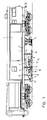
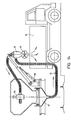
- Figure 1 is an overall view of the wagon profile milling machine carrying a milling device.
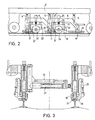
- Figure 2 is a side view of a first embodiment of the milling device.
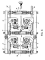
- Figure 3 is an end view in section of the device illustrated in figure 2.
- Figure 4 is a side view of a second embodiment of a milling unit illustrating the cutter in working position.
- Figure 5 is an elevational view of the unit of milling illustrated in figure 4 in change position of tool.
- Figure 6 is a top view of the device milling.
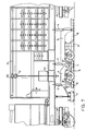
- Figure 7 is a side view in longitudinal section partial of the milling wagon illustrating the device tool storage and exchange.
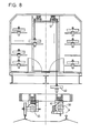
- Figure 8 is a cross section of the wagon milling showing a tool change.
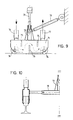
- Figure 9 is a side view of a cooling device of the rail.
- Figure 10 is an end view of the cooling device of the rail.
- Figure 11 is a view of the power car.
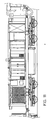
- Figure 12 is a side view of the grinding wagon.
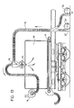
- Figure 13 is a detail view of the device chip extraction and storage during operation milling.
- Figure 14 shows the device allowing the chip discharge.
- the shaving milling and storage wagon illustrated in Figure 1 is the top element of the installation rail reprofiling.
- This wagon features, located at the front of the milling device, a device of measurement 1 which makes it possible to evaluate the deformations of the rail treat.
- the milling device is fixed to the chassis 2 of the rail vehicle 3 using cylinders 4,5,6 which keep the milling device in position work and take it up.
- a drawbar 7 connects the frame 2 to frame 9 of the milling device. This drawbar 7 allows training along the path of the device milling.
- the milling device has two frames 8.9 articulated between them. These 8.9 frames rest in three points on each rail through units of support and guide 10,11,12 of different lengths.
- Frames 8 and 9 have a different length, frame 8 bearing the milling unit 13 being longer than the frame 9 which carries the milling unit 14.
- These frames 8.9 each constitute a guiding base for the unit of milling 13,14 they carry. Milling unit 13 mounted by the longest frame 8 will eliminate the long undulations of the rail, while the milling unit 14 carried by the frame 9 will eliminate the ripples short.
- each of the milling units 13,14 is provided with a cutter as well as means for moving this cutter which will be described in detail below.
- each milling unit is pivoted on its support around a horizontal axis, for example as described with reference to Figures 4 and 5.
- Figure 1 further illustrates devices rail heating 15,16 located at the front of each two milling units 13,14 as well as a device cooling of the rail 17 located at the rear of the milling device. Heating devices from rail are mounted on the frames 8.9 respectively. Unity cooling 17 is towed by the second frame 9 using a drawbar.
- the measurement unit 1 of the rail deformations allows determine the depth of cut you want work the strawberries, as well as the power to provide heating units for forward speed given.
- FIG. 2 illustrates schematically and in more detail an embodiment of the milling device.
- This device comprises a first frame 8 connected via two cylinders 4,5 to chassis 2 of the vehicle. These 4.5 cylinders hold the frame 8 under the frame 2 and allow to raise it when walking high foot for example. In operation, these cylinders 4.5 allow press the milling unit against the rail with a determined force.
- the frame 8 seen from the side has a horizontal part extending approximately between the two cylinders 4 and 5. This horizontal part is extended by an amount oblique towards the front and vertical at the back.
- the amount oblique is connected to a first support device and guide 10.
- This device 10 is provided with rollers 18 which are in contact with the rail in the working position and guide shoes 19.
- a second support and guide 11 serves as a support for the rear upright of the frame 8.
- the milling device also has a second frame 9 carrying a second milling unit.
- the amount before oblique of the second frame 9 is articulated on the upright rear of frame 8 by means of an axis 20 perpendicular to the longitudinal axis of the rail.
- the rear upright of the frame 9 rests on a support and guide device 12 also fitted with castors and guide shoes. Both 8.9 hinged frames rest at three points on rails.
- Two guide columns 21,21 'integral with the part frame 8 extend perpendicularly to the latter towards the rail.
- a support 22 provided two bores corresponding to the guide columns 21.21 'is connected via a screw 23 to the frame 8.
- This support 22 includes a cutter 24 as well as the motor used for his training.
- a second milling unit is arranged in the same way under the frame 9.
- Figure 3 which is an end view of the device milling shows the device for adjusting the spacing 8.9 frames associated with each rail.
- a hydraulic cylinder 26 coupled to a guide device 27 allows to press the guide pads 19 against the inner flank of each rail. These pads 19 can be replaced by guide rollers bearing against the side inside the rail.
- the guide device is still provided with a guide roller 28 which is applied under the action of a jack 29 against the outer flank of the rail thereby ensuring perfect transverse guidance.
- the support and guiding devices 10,11,12 comprise several 18 wheels and skates 19. The 18 wheels can in a variant be replaced by support pads. These rollers 18 and their pads 19 can be spaced each other of a fixed value or according to a function determined.
- the first strawberry will be able to correct the longest ripples then that the second cutter 24 'carried and guided by a base 9 shorter corrects shorter ripples.
- the distance between the two strawberries is determined to ensure the best transfer function of the whole, i.e. the best correction for long ripples and short of the rail. We thus obtain not only a very sharp decrease in the amplitude of the defects, but also excellent surface quality thanks to the fact that the second 24 'cutter works at a cutting depth practically constant, the significant defects having been eliminated by the first cutter 24.
- FIG 2 again schematically illustrates a unit heater 31 mounted on chassis 22.
- This unit heating 31 makes it possible to bring the surface film of the rail head at a temperature of around a few hundred degrees, which greatly facilitates the work of strawberries 24.24 '.
- Working temperature is suitable for each type of rail steel. Heating is usually achieved through a heater by HF induction, but we can also consider a laser heater or other device allowing to quickly bring the surface layer of the rail at a high temperature.
- a second unit of heating (not shown) can be arranged on the support 22 'from the second cutter 24'.
- Rail heating allows on the one hand to increase productivity (speed of advancement and material removal) from milling by a factor of the order of 5 and on the other hand the wear of the cutters is reduced by a factor of the same order of magnitude.
- a suction device that collects the chips produced by strawberries. The suction device and chip storage is described with reference to Figure 13.
- FIGS 4,5 illustrate in detail a second form of execution of the milling units and their method of attachment to the frame which serves as their basis for guidance.
- the milling unit has a 40 cutter mounted on a mandrel 41.
- This milling cutter 40 is rotated by a motor 42 coupled to a drive 43 which can have a speed reducer or a clutch.
- This assembly is mounted on a support 44 via of a connecting element 45.
- This connecting element 45 is pivotally mounted on the support 44 along an axis contained in a vertical plane passing through an axis parallel to the longitudinal axis of the rail.
- Means (not shown) are arranged in the support 44 allowing the position to be varied angle of the connecting element 45 relative to the support 44 under the action of a control member.
- the frame 8 which serves as a guide base for the milling unit comprises a part 46 provided with a mechanical stop 47.
- the support 44 is pivotally mounted on part 46 around a axis 48.
- a jack 49 whose rod is integral of the support 44, and the cylinder of which is fixed to the piece 46, it is possible to move the cutter 40 in the vertical plane perpendicular to the rails. This allows to bring the cutter more or less close to the rail in function the desired depth of cut for reprofiling.
- the milling unit in the raised position is indicated in dotted in Figure 4.
- Figure 6 illustrates the milling device seen from above which has four milling units arranged in their respective frames 8,9,8 ', 9'.
- the spacers 26 allow to adjust the spacing between the devices support and guide 10,10 ', 11,11', 12,12 on which rest the frames 8,9,8 ', 9' which carry the milling units.
- the shaving milling and storage wagon illustrated in longitudinal section in Figure 7 shows the device which allows the tool to be changed from the inside from the wagon.
- a carriage 50 carrying a hoist 51 can be move longitudinally along a rail 52 fixed to the ceiling of the wagon and come and load a cutter located in the front part of the wagon which constitutes the stock of strawberries.
- the cutter is brought through the hoist 51 through an opening 53 made in the floor of the wagon, at above the milling unit on which you wish to perform a tool change.
- FIG 8 shows in another view the principle of change of strawberries.
- Milling unit 55 located on the left of the figure is in train service position to mill the rail, while the milling unit 56 is illustrated in a position allowing the change of the tool after having been rotated 90 ° around a axis parallel to the rail in the direction of arrow F.
- the hoist 51 can align the cutter 40 in look of the mandrel 41 of the milling unit. Fixation by Morse taper of the strawberry allows a quick change and easy strawberries.
- FIG. 9 illustrates the cooling system 17 located at the rear of the milling units. These measures is connected to chassis 2 of the rail vehicle by a jack 70 which allows the said device to be raised.
- the piston of this jack 70 is connected to the frame 71 of the cooler via a connecting piece 72.
- This piece link 72 also receives one end of a drawbar 73 the other end of which is integral with frame 9 forming the guide base of the second milling unit.
- This drawbar 73 allows the drive and guidance of cooler.
- the frame 71 of the cooler includes guide rollers 74 which come to bear on the rail in service position. Inside the frame 71, baffles 75 are arranged in such a way that they cause a vortex flow of the coolant which circulates in the frame.
- Frame 71 has still on the upper part an entry 76 and an exit 77 of the coolant.
- Figure 10 illustrates in partial section the cooler and shows a jack 78 connected to the connecting piece 72 and which makes it possible to adjust the spacing between the coolers associated with each rails and thereby ensure transverse guidance coolers on the rails.
- FIG 11 illustrates the power wagon used in the rail reprofiling installation.
- This wagon of power provides the electrical energy needed to power milling units as well as food heating units.
- This power wagon is located behind the milling wagon which is at the head of the convoy and in front of a wagon shown in Figure 12 carrying units 80.81 grinding and finishing to eliminate the streaks left on the rail by the work of strawberries.
- These grinding or polishing units are by example of the type described in US Patents 4,615,150 or US 5,265,379.
- the grinding wheels used may be grinding wheels lapidaries, peripheral, grinding stones or reciprocating shaped abrasive blocks.
- This wagon is also equipped with a suction device and storage of dust produced by grinding.
- the cart also has a measuring unit 82 located behind the grinding units. This unit 82 allows to measure the quality of the reprofiling obtained and thanks to a servo control of milling units and heating, correct the setting of the cutting depth of milling units, and / or power heating of the heating units.
- FIG 13 illustrates in detail the device for chip extraction and storage during operation milling.
- the rear part of the milling wagon has a 90 chip container.
- a conveyor belt 91 is arranged in the bottom of the container 90.
- Behind each strawberries 24,24 'there is a suction mouth 32.32 'connected to a suction pipe 92 which opens in a separating device 93.
- a fan 94 fixed on the wagon, causes the aspiration of the chips which fall into device 93.
- This device 93 is provided blades 95 driven in rotation which prevent accumulation chips inside the device and facilitates their evacuation to container 90 and their distribution In this one.
- FIG 14 illustrates the operation of unloading shavings.
- a tipper truck 96 is parked near the installation.
- the pipe 92 is disconnected from the end piece connecting the 32.32 'suction ports and connect it to the outlet a discharge container 97 located below the container 90 and into which the conveyor belt 91 opens. turning on the treadmill 91 causes evacuation chips to the discharge container 97.
- a 98 pivot hydraulic crane mounted on the wagon milling tool moves the separating device 93 above the dump truck 96.
- the fan 94 causes then the suction of the chips which have fallen into the container discharge 97 to the separating device 93 which dumped into the truck’s dumpster.
- the chip extraction can be replaced by a device like a magnetic drum which allows collect the chips by magnetic attraction.
- the reprofiling installation as described comprises a milling wagon at the front, a power wagon in the center and a wagon for grinding and polishing rails. It goes without saying that these operations can be dissociated if for example the working speeds are not the same for the different operations. Likewise, we can provide that the different units (milling, heating, measurement, grinding) are arranged under a vehicle unique.
Landscapes
- Engineering & Computer Science (AREA)
- Mechanical Engineering (AREA)
- Architecture (AREA)
- Civil Engineering (AREA)
- Structural Engineering (AREA)
- Machines For Laying And Maintaining Railways (AREA)
- Train Traffic Observation, Control, And Security (AREA)
- Forklifts And Lifting Vehicles (AREA)
- Investigating Or Analyzing Materials By The Use Of Magnetic Means (AREA)
- Railway Tracks (AREA)
- Linear Motors (AREA)
- Machine Tool Units (AREA)
Claims (13)
- Vorrichtung zur Nachprofilierung von zumindest einer verlegten Eisenbahnschiene mit zumindest zwei Bearbeitungseinheiten (13, 14), die unter einem Schienenfahrzeug (3) angebracht sind, mit Hilfe von Hebeorganen und Organen zum Andrücken an die Schiene (4, 5, 6) bezüglich dieses Fahrzeugs verschoben werden können und zumindest je ein von einem Motor in Drehbewegung versetztes Werkzeug enthalten; wobei jede Bearbeitungseinheit (13, 14) auf einem Träger sitzt, der bezüglich eines entlang der Schiene geführten und mit dem Fahrzeug durch die benannten Hebeorgane (4, 5, 6) verbundenen Rahmens (8, 9) in der Senkrechten verschoben werden kann; und diese beiden Rahmen (8, 9) gelenkig in einer zur Schienenlängsachse senkrechten Achse (20) miteinander verbunden sind sowie verschiedene Längen aufweisen, dadurch gekennzeichnet, dass die Werkzeuge (24, 40) Fräsen sind; dass die Fräseinheiten (13, 14) bezüglich des entsprechenden Rahmens (8, 9) zur Hinterseite dieses Rahmens hin versetzt sind; dass Steuerorgane (23, 25) die Stellung des Trägers jeder Einheit (13, 14) bezüglich des entsprechenden Rahmens (8, 9) definieren; dass der eine (8) der Rahmen (8, 9) vermittels Auflagevorrichtungen (10, 11) von unterschiedlicher Länge, wobei die längere (10) sich an der Vorderseite des Rahmens (8) befindet, auf der Schiene ruht; und dass die Fräseinheiten (13, 14) auf ihrem Träger um eine waagerechte Achse geschwenkt werden können, wodurch die Fräsen (24, 40) von einer Arbeitsstellung, in der ihre Drehachsen im wesentlichen waagerecht liegen, in eine Stellung für den Fräsenwechsel gekippt werden können, in der die Drehachse der Fräse senkrecht ist.
- Vorrichtung gemäss Anspruch 1, dadurch gekennzeichnet, dass die Auflagevorrichtungen (10, 11, 12) des Rahmens auf den Schienen Rollen (18) oder Gleitschuhe in Berührung mit der Schienenlauffläche sowie Gleitschuhe oder Führungsrollen (28) umfassen, die gegen die Schienenflanke gedrückt werden.
- Vorrichtung gemäss Anspruch 1 oder Anspruch 2, dadurch gekennzeichnet, dass sie im Inneren des Schienenfahrzeugs (3) über den Fräseinheiten (13, 14) einen Vorrat an Fräsen sowie eine Einrichtung (53) für die Handhabung dieser Fräsen umfasst, die es gestattet, die Fräsen von ihrem Aufbewahrungsort bis zur Stellung der Beschickung einer Fräseinheit zu bringen.
- Vorrichtung gemäss einem der vorangehenden Ansprüche, dadurch gekennzeichnet, dass die Rahmen (8, 9), die die jeder der Schienen zugeordneten Fräseinheiten (13, 14) tragen, durch Winden (26) miteinander verbunden sind, mit denen der Abstand zwischen diesen Rahmen (8, 9) eingestellt werden kann.
- Vorrichtung gemäss einem der vorangehenden Ansprüche, dadurch gekennzeichnet, dass sie zumindest eine Einheit (15, 16) zum Aufheizen der Schiene im Vorfeld einer Fräseinheit (13, 14) umfasst.
- Fräseinheit gemäss einem der vorangehenden Ansprüche, dadurch gekennzeichnet, dass sie eine Kühleinheit (17) umfasst, die sich hinter den Fräseinheiten (13, 14) befindet.
- Vorrichtung gemäss einem der vorangehenden Ansprüche, dadurch gekennzeichnet, dass sie Organe (32, 90, 92, 93) für die Rückgewinnung und Aufbewahrung der von den Fräsen erzeugten Späne umfasst.
- Vorrichtung gemäss einem der vorangehenden Ansprüche, dadurch gekennzeichnet, dass die Organe für die Rückgewinnung der Späne aus einem Ansaugkanal (92) bestehen, dessen Einlass (32) sich hinter der Fräse (24) befindet und der in einen Behälter (90) mündet, der in das die Fräseinheiten (13, 14) tragende Schienenfahrzeug integriert ist.
- Vorrichtung gemäss einem der vorangehenden Ansprüche, dadurch gekennzeichnet, dass die Organe für die Rückgewinnung der Frässpäne aus einer Vorrichtung bestehen, die eine magnetische Anziehung der Späne gestattet.
- Vorrichtung gemäss einem der vorangehenden Ansprüche, dadurch gekennzeichnet, dass sie eine Einheit (1) zur Messung der Schienendefekte umfasst, die vor den Fräseinheiten (13, 14) angeordnet ist und es gestattet, die Schnitttiefe der Werkzeuge, die den Aufheizeinheiten zuzuführende Leistung und die Vorschubgeschwindigkeit der Vorrichtung zu bestimmen.
- Vorrichtung gemäss einem der vorangehenden Ansprüche, dadurch gekennzeichnet, dass sie ein zweites Schienenfahrzeug umfasst, das mit einer Vorrichtung zum Schleifen oder Polieren der Schienen ausgerüstet ist und sich hinter dem mit den Fräsvorrichtungen ausgerüsteten Fahrzeug befindet.
- Vorrichtung gemäss Anspruch 11, dadurch gekennzeichnet, dass sie eine Einheit (82) zur Messung der Schienendefekte umfasst, die sich hinter den Schleifeinheiten befindet.
- Vorrichtung gemäss einem der vorangehenden Ansprüche, dadurch gekennzeichnet, dass sie einen Trieb- und Energieversorgungswagen umfasst, der mit Generatoren ausgerüstet ist und sich zwischem dem mit der Fräsvorrichtung und dem mit der Schienenpoliervorrichtung ausgerüsteten Fahrzeug befindet.
Applications Claiming Priority (2)
| Application Number | Priority Date | Filing Date | Title |
|---|---|---|---|
| CH497/94 | 1994-02-18 | ||
| CH00497/94A CH689642A5 (fr) | 1994-02-18 | 1994-02-18 | Installation pour le reprofilage des rails d'une voie ferrée. |
Publications (2)
| Publication Number | Publication Date |
|---|---|
| EP0668397A1 EP0668397A1 (de) | 1995-08-23 |
| EP0668397B1 true EP0668397B1 (de) | 1998-05-20 |
Family
ID=4188359
Family Applications (1)
| Application Number | Title | Priority Date | Filing Date |
|---|---|---|---|
| EP94119363A Expired - Lifetime EP0668397B1 (de) | 1994-02-18 | 1994-12-08 | Vorrichtung zur Wiederprofilierung von Eisenbahnschienen |
Country Status (10)
| Country | Link |
|---|---|
| US (1) | US5549505A (de) |
| EP (1) | EP0668397B1 (de) |
| JP (1) | JPH07229103A (de) |
| AT (1) | ATE166406T1 (de) |
| AU (1) | AU678067B2 (de) |
| CA (1) | CA2137864C (de) |
| CH (1) | CH689642A5 (de) |
| DE (1) | DE69410430T2 (de) |
| HK (1) | HK1008846A1 (de) |
| ZA (1) | ZA949649B (de) |
Cited By (5)
| Publication number | Priority date | Publication date | Assignee | Title |
|---|---|---|---|---|
| DE19721291C2 (de) * | 1996-05-24 | 2003-10-09 | Integral Verkehrstechnik Ag Je | Schienenfahrzeug |
| EP2177664A1 (de) | 2008-10-20 | 2010-04-21 | Mevert Maschinenbau GmbH & Co.KG | Verfahren und Vorrichtung zum spanabhebenden Bearbeiten eines Werkstücks mit einer geometrisch bestimmten Schneide |
| WO2022135814A2 (de) | 2020-12-22 | 2022-06-30 | Schweerbau International Gmbh & Co. Kg | Vorrichtung und verfahren zum schleifen eines profils |
| WO2022135975A1 (de) | 2020-12-22 | 2022-06-30 | Schweerbau International Gmbh & Co. Kg | Vorrichtung mit einem rotationsbeweglich antreibbaren fräskörper |
| WO2022135832A1 (de) | 2020-12-22 | 2022-06-30 | Schweerbau International Gmbh & Co. Kg | Vorrichtung zum fräsen eines profils, zugehöriges verfahren und referenzkörper |
Families Citing this family (19)
| Publication number | Priority date | Publication date | Assignee | Title |
|---|---|---|---|---|
| US6033166A (en) * | 1998-08-27 | 2000-03-07 | Koppers Industries, Inc. | Rail milling machine |
| CA2516191A1 (en) * | 2003-02-14 | 2004-09-02 | Salmedix, Inc | Compositions and methods for the detection and treatment of methylthioadenosine phosphorylase deficient cancers |
| CA2487387C (en) * | 2004-12-01 | 2010-02-23 | David Fenton | Rail grooming machine and method of use |
| CH698609B1 (fr) * | 2005-09-16 | 2009-09-15 | Speno Internat S A | Dispositif de reprofilage des rails de chemins de fer avec captage des déchets. |
| JP5508753B2 (ja) * | 2009-04-10 | 2014-06-04 | 東鉄工業株式会社 | レール錆取り機 |
| AT509530B1 (de) * | 2010-02-25 | 2012-01-15 | Linsinger Maschb Gesmbh | Fahrbare vorrichtung zum bearbeiten von schienenköpfen |
| KR101279453B1 (ko) * | 2011-08-25 | 2013-06-27 | 한국철도기술연구원 | 노면 그라인딩 장치 |
| CN104612005B (zh) * | 2013-11-04 | 2017-02-22 | 中国铁建高新装备股份有限公司 | 再成形钢轨轨头轮廓的加工方法 |
| CN104612006B (zh) * | 2013-11-04 | 2017-03-22 | 中国铁建高新装备股份有限公司 | 再成形钢轨轨头轮廓的加工设备 |
| CN103911925A (zh) * | 2014-04-22 | 2014-07-09 | 北京二七机车工业有限责任公司 | 钢轨打磨车架体 |
| CN103911926A (zh) * | 2014-04-22 | 2014-07-09 | 北京二七机车工业有限责任公司 | 钢轨打磨车 |
| EP2947204B1 (de) * | 2014-05-19 | 2017-01-11 | Mevert Maschinenbau GmbH & Co.KG | Verfahrbare Vorrichtung zum Fräsen von Schienenköpfen und Verfahren zum Wechsel von Schneidplatten bei einer derartigen Vorrichtung |
| CN105625121B (zh) * | 2014-10-31 | 2018-03-27 | 中国铁建高新装备股份有限公司 | 一种铁路钢轨廓形铣磨设备 |
| CN104942346B (zh) * | 2015-06-30 | 2017-06-06 | 株洲时代电子技术有限公司 | 一种钢轨铣削作业控制系统 |
| CN104923840B (zh) * | 2015-06-30 | 2017-09-22 | 株洲时代电子技术有限公司 | 一种钢轨铣削作业控制方法 |
| US20180245292A1 (en) | 2017-02-24 | 2018-08-30 | Holland, L.P. | Portable Weld Milling Machine Apparatus and Methods of Using the Same |
| CN106141765A (zh) * | 2016-08-26 | 2016-11-23 | 湖南大学 | 一种用于钢轨整修的铣削装置 |
| CA3110958A1 (en) | 2018-08-27 | 2020-03-05 | Harsco Technologies LLC | Rail milling vehicle |
| AT523240B1 (de) | 2019-12-04 | 2024-01-15 | Mate Gmbh | Reprofilierungsverfahren an zumindest einer Schiene |
Family Cites Families (19)
| Publication number | Priority date | Publication date | Assignee | Title |
|---|---|---|---|---|
| AT234137B (de) * | 1959-02-13 | 1964-06-10 | Karl Gerlach | Vorrichtung zum Nachprofilieren der Lauffläche und Fahrkante abgefahrener Eisenbahnschienen |
| CH581232A5 (de) * | 1975-01-13 | 1976-10-29 | Speno International | |
| CH583337A5 (de) * | 1975-02-25 | 1976-12-31 | Speno International | |
| CH614476A5 (de) * | 1977-10-10 | 1979-11-30 | Scheuchzer Auguste Les Fils D | |
| CH616186A5 (en) * | 1977-11-04 | 1980-03-14 | Scheuchzer Auguste Les Fils D | Machine for grinding railway rails |
| AT361025B (de) * | 1978-02-10 | 1981-02-10 | Plasser Bahnbaumasch Franz | Gleisverfahrbare maschine zum bearbeiten der schienenkopfoberflaechen |
| AT368220B (de) * | 1979-08-14 | 1982-09-27 | Plasser Bahnbaumasch Franz | Maschine zur bearbeitung der schienenkopfoberfl[che eines verlegten gleises |
| CH633336A5 (fr) * | 1980-01-09 | 1982-11-30 | Speno International | Machine de chantier ferroviaire pour la rectification du champignon des rails. |
| AT368219B (de) * | 1980-01-17 | 1982-09-27 | Plasser Bahnbaumasch Franz | Verfahren zum entfernen von unregelmaessigkeiten an der schienenkopfoberflaeche verlegter gleise |
| AT369071B (de) * | 1980-01-17 | 1982-12-10 | Plasser Bahnbaumasch Franz | Gleisverfahrbare maschine zum entfernen von unregelmaessigkeiten an der schienenkopfoberflaeche verlegter gleise |
| DE3222208C2 (de) * | 1982-06-12 | 1985-03-28 | Dr. techn. Ernst Linsinger & Co GmbH, Steyrermühl | Verfahrbare Vorrichtung zum Fräsen von Schienenköpfen |
| CH654047A5 (fr) * | 1983-09-16 | 1986-01-31 | Speno International | Procede et dispositif pour le reprofilage en continu des rails d'une voie ferree. |
| CH666068A5 (fr) * | 1983-11-16 | 1988-06-30 | Speno International | Dispositif pour le reprofilage en continu du champignon d'au moins un rail. |
| US4583327A (en) * | 1983-11-25 | 1986-04-22 | Jackson Jordan, Inc. | Rail grinding car |
| GB8626051D0 (en) * | 1986-10-31 | 1986-12-03 | Seguin H J J | Laser surface hardening of rails |
| CH671595A5 (en) * | 1987-05-14 | 1989-09-15 | Speno International | Railway line rectifier - has filtering system with fan to remove and separate abrasive and metal particles |
| CH675440A5 (de) * | 1988-03-04 | 1990-09-28 | Speno International | |
| CH680672A5 (de) * | 1989-08-28 | 1992-10-15 | Speno International | |
| FR2659584B1 (fr) * | 1990-03-14 | 1992-06-12 | Levy Marcel | Machine a reprofiler les rails de chemin de fer uses. |
-
1994
- 1994-02-18 CH CH00497/94A patent/CH689642A5/fr not_active IP Right Cessation
- 1994-12-01 US US08/352,156 patent/US5549505A/en not_active Expired - Fee Related
- 1994-12-02 AU AU79196/94A patent/AU678067B2/en not_active Ceased
- 1994-12-05 ZA ZA949649A patent/ZA949649B/xx unknown
- 1994-12-08 AT AT94119363T patent/ATE166406T1/de not_active IP Right Cessation
- 1994-12-08 DE DE69410430T patent/DE69410430T2/de not_active Expired - Fee Related
- 1994-12-08 EP EP94119363A patent/EP0668397B1/de not_active Expired - Lifetime
- 1994-12-12 CA CA002137864A patent/CA2137864C/en not_active Expired - Fee Related
- 1994-12-15 JP JP6332837A patent/JPH07229103A/ja active Pending
-
1998
- 1998-07-31 HK HK98109565A patent/HK1008846A1/xx not_active IP Right Cessation
Cited By (6)
| Publication number | Priority date | Publication date | Assignee | Title |
|---|---|---|---|---|
| DE19721291C2 (de) * | 1996-05-24 | 2003-10-09 | Integral Verkehrstechnik Ag Je | Schienenfahrzeug |
| EP2177664A1 (de) | 2008-10-20 | 2010-04-21 | Mevert Maschinenbau GmbH & Co.KG | Verfahren und Vorrichtung zum spanabhebenden Bearbeiten eines Werkstücks mit einer geometrisch bestimmten Schneide |
| US9528225B2 (en) | 2008-10-20 | 2016-12-27 | Schweerbau Gmbh & Co. Kg | Method and apparatus for machining a workpiece by way of a geometrically defined blade |
| WO2022135814A2 (de) | 2020-12-22 | 2022-06-30 | Schweerbau International Gmbh & Co. Kg | Vorrichtung und verfahren zum schleifen eines profils |
| WO2022135975A1 (de) | 2020-12-22 | 2022-06-30 | Schweerbau International Gmbh & Co. Kg | Vorrichtung mit einem rotationsbeweglich antreibbaren fräskörper |
| WO2022135832A1 (de) | 2020-12-22 | 2022-06-30 | Schweerbau International Gmbh & Co. Kg | Vorrichtung zum fräsen eines profils, zugehöriges verfahren und referenzkörper |
Also Published As
| Publication number | Publication date |
|---|---|
| ZA949649B (en) | 1995-08-01 |
| CA2137864A1 (en) | 1995-08-19 |
| AU678067B2 (en) | 1997-05-15 |
| JPH07229103A (ja) | 1995-08-29 |
| EP0668397A1 (de) | 1995-08-23 |
| DE69410430T2 (de) | 1998-12-10 |
| AU7919694A (en) | 1995-08-31 |
| ATE166406T1 (de) | 1998-06-15 |
| CA2137864C (en) | 2000-02-29 |
| CH689642A5 (fr) | 1999-07-30 |
| US5549505A (en) | 1996-08-27 |
| DE69410430D1 (de) | 1998-06-25 |
| HK1008846A1 (en) | 1999-05-21 |
Similar Documents
| Publication | Publication Date | Title |
|---|---|---|
| EP0668398B1 (de) | Vorrichtung zur Wiederprofilierung von Eisenbahnschienen | |
| EP0668397B1 (de) | Vorrichtung zur Wiederprofilierung von Eisenbahnschienen | |
| FR2474076A1 (fr) | Procede d'elimination des defauts des champignons des rails d'une voie ferree posee et machine permettant son execution | |
| EP0955154B1 (de) | Reifenrunderneuerungsvorrichtung | |
| EP0141948B1 (de) | Verfahren und Vorrichtung zum durchlaufenden Rektifizieren von Eisenbahnschienen | |
| EP0743399A1 (de) | Gleisreinigungsvorrichtung | |
| FR2463230A1 (fr) | Machine de traitement de la surface des champignons des rails d'une voie ferree posee | |
| EP0017520B1 (de) | Vorrichtung zum Ausrichten und Halten von zwei zu verschweissenden Schienenenden | |
| HK1008846B (en) | Device for reshaping railway rails | |
| FR3025128A1 (fr) | Installation de fraisage pour brames d'aluminium | |
| EP0501183B1 (de) | Vorrichtung zur Wiederprofilierung von Eisenbahnschienen | |
| EP0417452B1 (de) | Verfahren zum Programmieren der Wiederprofilierungsarbeiten von Eisenbahnschienen und/oder der Wiederprofilierung dieser Schienen und Vorrichtung zur Durchführung des Verfahrens | |
| FR2615216A1 (fr) | Appareil de meulage a ruban pour une machine a meuler les rails pour le meulage d'irregularites a la surface du champignon de rail d'un ou des deux rails d'une voie ferree posee | |
| FR2463228A1 (fr) | Machine mobile sur une voie ferree servant a eliminer les defauts de surface des rails | |
| CA2216576A1 (fr) | Dispositif pour la finition du reprofilage en voie et en continu de la surface du champignon d'au moins un rail d'une voie ferree | |
| CH686144A5 (fr) | Train de renouvellement d'une voie ferree. | |
| FR2618464A1 (fr) | Dispositif roulant sur voie ferree pour le deblayage et/ou le nivellement du ballast d'une voie ferree a traverses | |
| FR2463229A1 (fr) | Machine a raboter equipee de rabots et se deplacant sur une voie ferree et outils de rabotage equipant une telle machine | |
| FR2808871A1 (fr) | Dispositif de mesure de chassis et procede pour mesurer un chassis | |
| FR2847917A1 (fr) | Procede de pose ou de renouvellement des rails d'une voie de chemin de fer, et installation pour la mise en oeuvre de ce procede | |
| EP0606787B1 (de) | Vorrichtung zur Bearbeitung der Laufflächen von Schienen, insbesondere zur Entzunderung und Riffelrektifikation | |
| FR2884747A1 (fr) | Rectifieuse d'eprouvettes cylindriques, notamment en beton | |
| EP0888230B1 (de) | Vorrichtung zum Unterhalt und zur Reparatur von Eisenbahngleisen | |
| FR2667629A1 (fr) | Procede de meulage de rails et appareils pour la mise en óoeuvre de ce procede. | |
| FR2911350A1 (fr) | Procede et machine pour l'echange de traverses a deux blocs d'une voie ferree. |
Legal Events
| Date | Code | Title | Description |
|---|---|---|---|
| PUAI | Public reference made under article 153(3) epc to a published international application that has entered the european phase |
Free format text: ORIGINAL CODE: 0009012 |
|
| AK | Designated contracting states |
Kind code of ref document: A1 Designated state(s): AT BE CH DE FR GB IT LI NL SE |
|
| 17P | Request for examination filed |
Effective date: 19950911 |
|
| 17Q | First examination report despatched |
Effective date: 19970502 |
|
| GRAG | Despatch of communication of intention to grant |
Free format text: ORIGINAL CODE: EPIDOS AGRA |
|
| GRAG | Despatch of communication of intention to grant |
Free format text: ORIGINAL CODE: EPIDOS AGRA |
|
| GRAH | Despatch of communication of intention to grant a patent |
Free format text: ORIGINAL CODE: EPIDOS IGRA |
|
| GRAH | Despatch of communication of intention to grant a patent |
Free format text: ORIGINAL CODE: EPIDOS IGRA |
|
| GRAA | (expected) grant |
Free format text: ORIGINAL CODE: 0009210 |
|
| AK | Designated contracting states |
Kind code of ref document: B1 Designated state(s): AT BE CH DE FR GB IT LI NL SE |
|
| REF | Corresponds to: |
Ref document number: 166406 Country of ref document: AT Date of ref document: 19980615 Kind code of ref document: T |
|
| ITF | It: translation for a ep patent filed | ||
| REG | Reference to a national code |
Ref country code: CH Ref legal event code: NV Representative=s name: MICHELI & CIE INGENIEURS-CONSEILS Ref country code: CH Ref legal event code: EP |
|
| REF | Corresponds to: |
Ref document number: 69410430 Country of ref document: DE Date of ref document: 19980625 |
|
| GBT | Gb: translation of ep patent filed (gb section 77(6)(a)/1977) |
Effective date: 19980706 |
|
| PLBE | No opposition filed within time limit |
Free format text: ORIGINAL CODE: 0009261 |
|
| STAA | Information on the status of an ep patent application or granted ep patent |
Free format text: STATUS: NO OPPOSITION FILED WITHIN TIME LIMIT |
|
| 26N | No opposition filed | ||
| PGFP | Annual fee paid to national office [announced via postgrant information from national office to epo] |
Ref country code: GB Payment date: 20001123 Year of fee payment: 7 |
|
| PGFP | Annual fee paid to national office [announced via postgrant information from national office to epo] |
Ref country code: NL Payment date: 20001127 Year of fee payment: 7 |
|
| PGFP | Annual fee paid to national office [announced via postgrant information from national office to epo] |
Ref country code: AT Payment date: 20001128 Year of fee payment: 7 |
|
| PGFP | Annual fee paid to national office [announced via postgrant information from national office to epo] |
Ref country code: DE Payment date: 20001201 Year of fee payment: 7 |
|
| PGFP | Annual fee paid to national office [announced via postgrant information from national office to epo] |
Ref country code: SE Payment date: 20001204 Year of fee payment: 7 Ref country code: FR Payment date: 20001204 Year of fee payment: 7 |
|
| PGFP | Annual fee paid to national office [announced via postgrant information from national office to epo] |
Ref country code: BE Payment date: 20001207 Year of fee payment: 7 |
|
| PGFP | Annual fee paid to national office [announced via postgrant information from national office to epo] |
Ref country code: CH Payment date: 20010301 Year of fee payment: 7 |
|
| PG25 | Lapsed in a contracting state [announced via postgrant information from national office to epo] |
Ref country code: GB Free format text: LAPSE BECAUSE OF NON-PAYMENT OF DUE FEES Effective date: 20011208 Ref country code: AT Free format text: LAPSE BECAUSE OF NON-PAYMENT OF DUE FEES Effective date: 20011208 |
|
| PG25 | Lapsed in a contracting state [announced via postgrant information from national office to epo] |
Ref country code: SE Free format text: LAPSE BECAUSE OF NON-PAYMENT OF DUE FEES Effective date: 20011209 |
|
| PG25 | Lapsed in a contracting state [announced via postgrant information from national office to epo] |
Ref country code: LI Free format text: LAPSE BECAUSE OF NON-PAYMENT OF DUE FEES Effective date: 20011231 Ref country code: CH Free format text: LAPSE BECAUSE OF NON-PAYMENT OF DUE FEES Effective date: 20011231 Ref country code: BE Free format text: LAPSE BECAUSE OF NON-PAYMENT OF DUE FEES Effective date: 20011231 |
|
| REG | Reference to a national code |
Ref country code: GB Ref legal event code: IF02 |
|
| BERE | Be: lapsed |
Owner name: S.A. SPENO INTERNATIONAL Effective date: 20011231 |
|
| PG25 | Lapsed in a contracting state [announced via postgrant information from national office to epo] |
Ref country code: NL Free format text: LAPSE BECAUSE OF NON-PAYMENT OF DUE FEES Effective date: 20020701 |
|
| PG25 | Lapsed in a contracting state [announced via postgrant information from national office to epo] |
Ref country code: DE Free format text: LAPSE BECAUSE OF NON-PAYMENT OF DUE FEES Effective date: 20020702 |
|
| EUG | Se: european patent has lapsed |
Ref document number: 94119363.3 |
|
| GBPC | Gb: european patent ceased through non-payment of renewal fee |
Effective date: 20011208 |
|
| REG | Reference to a national code |
Ref country code: CH Ref legal event code: PL |
|
| PG25 | Lapsed in a contracting state [announced via postgrant information from national office to epo] |
Ref country code: FR Free format text: LAPSE BECAUSE OF NON-PAYMENT OF DUE FEES Effective date: 20020830 |
|
| NLV4 | Nl: lapsed or anulled due to non-payment of the annual fee |
Effective date: 20020701 |
|
| REG | Reference to a national code |
Ref country code: FR Ref legal event code: ST |
|
| PG25 | Lapsed in a contracting state [announced via postgrant information from national office to epo] |
Ref country code: IT Free format text: LAPSE BECAUSE OF NON-PAYMENT OF DUE FEES;WARNING: LAPSES OF ITALIAN PATENTS WITH EFFECTIVE DATE BEFORE 2007 MAY HAVE OCCURRED AT ANY TIME BEFORE 2007. THE CORRECT EFFECTIVE DATE MAY BE DIFFERENT FROM THE ONE RECORDED. Effective date: 20051208 |