EP0664735B1 - A universal support and positioning structure for tools usable by an elongate element bending machine - Google Patents
A universal support and positioning structure for tools usable by an elongate element bending machine Download PDFInfo
- Publication number
- EP0664735B1 EP0664735B1 EP93908889A EP93908889A EP0664735B1 EP 0664735 B1 EP0664735 B1 EP 0664735B1 EP 93908889 A EP93908889 A EP 93908889A EP 93908889 A EP93908889 A EP 93908889A EP 0664735 B1 EP0664735 B1 EP 0664735B1
- Authority
- EP
- European Patent Office
- Prior art keywords
- support platform
- fact
- plate
- support
- frame
- Prior art date
- Legal status (The legal status is an assumption and is not a legal conclusion. Google has not performed a legal analysis and makes no representation as to the accuracy of the status listed.)
- Expired - Lifetime
Links
- 238000005452 bending Methods 0.000 title claims abstract description 20
- 230000008878 coupling Effects 0.000 claims description 2
- 238000010168 coupling process Methods 0.000 claims description 2
- 238000005859 coupling reaction Methods 0.000 claims description 2
- 238000010276 construction Methods 0.000 description 1
- 230000000694 effects Effects 0.000 description 1
- 238000000034 method Methods 0.000 description 1
- 230000000717 retained effect Effects 0.000 description 1
Images

Classifications
-
- B—PERFORMING OPERATIONS; TRANSPORTING
- B21—MECHANICAL METAL-WORKING WITHOUT ESSENTIALLY REMOVING MATERIAL; PUNCHING METAL
- B21D—WORKING OR PROCESSING OF SHEET METAL OR METAL TUBES, RODS OR PROFILES WITHOUT ESSENTIALLY REMOVING MATERIAL; PUNCHING METAL
- B21D7/00—Bending rods, profiles, or tubes
-
- B—PERFORMING OPERATIONS; TRANSPORTING
- B21—MECHANICAL METAL-WORKING WITHOUT ESSENTIALLY REMOVING MATERIAL; PUNCHING METAL
- B21D—WORKING OR PROCESSING OF SHEET METAL OR METAL TUBES, RODS OR PROFILES WITHOUT ESSENTIALLY REMOVING MATERIAL; PUNCHING METAL
- B21D11/00—Bending not restricted to forms of material mentioned in only one of groups B21D5/00, B21D7/00, B21D9/00; Bending not provided for in groups B21D5/00 - B21D9/00; Twisting
- B21D11/06—Bending into helical or spiral form; Forming a succession of return bends, e.g. serpentine form
- B21D11/07—Making serpentine-shaped articles by bending essentially in one plane
-
- B—PERFORMING OPERATIONS; TRANSPORTING
- B21—MECHANICAL METAL-WORKING WITHOUT ESSENTIALLY REMOVING MATERIAL; PUNCHING METAL
- B21D—WORKING OR PROCESSING OF SHEET METAL OR METAL TUBES, RODS OR PROFILES WITHOUT ESSENTIALLY REMOVING MATERIAL; PUNCHING METAL
- B21D7/00—Bending rods, profiles, or tubes
- B21D7/02—Bending rods, profiles, or tubes over a stationary forming member; by use of a swinging forming member or abutment
- B21D7/022—Bending rods, profiles, or tubes over a stationary forming member; by use of a swinging forming member or abutment over a stationary forming member only
Definitions
- the present invention relates to a support and positioning structure for tools usable by a machine for bending elongate elements such as tubes or profiled sections.
- the present invention relates to a support and positioning structure having the features indicated in the preamble of claim 1.
- a structure of this kind is disclosed in prior document US-A-2 884 987.
- the object of the present invention is that of providing a structure of the type indicated above which is adapted for use in positioning and supporting various tools used for bending elongate elements of widely varying forms, thereby obtaining apparatus which is not excessively complex and which operates simply and with wide versatility in use.
- said base body and support platform form part of a slide movably mounted on a support frame, means being provided for moving the slide relative to this latter in at least one direction.
- the structure according to the invention comprises two slides movably mounted on a single support frame and each comprising a respective base body and a respective support platform.
- the slides are conveniently positioned with respect to the frame by their associated movement-drive means. Then the tools required by the type of bending which is intended to effect are positioned on the support platforms of the slides. Subsequently the bending operation itself is effected by a suitable combined translational and rotational movement of the support platforms about their respective pivots.
- the rotational movement allows the desired curvature to be obtained, whilst the translational movement, which takes place contemporaneously with the rotational movement, causes the curved element to yield so that it can no longer reassume its original, undeformed configuration as a result of the elastic restoring forces, once the bending stress has been released.
- the present invention also comprehends a machine for bending elongate elements including a tool support and positioning structure of the type indicated above.
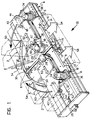
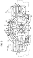
- a universal support and positioning structure for tools used by a bending machine ( Figures 1 to 3) includes a pair of slides 2 slidably mounted on a support frame 4.
- Each slide 2 comprises a flat base body 6 connected to a first plate 8 slidable on a second plate 10 by means of a pair of projections 12 which fit into respective grooves 14 formed in the second plate 10.
- This latter is in turn slidable on the frame 4 by means of a pair of terminal coupling elements 16 which engage respective guides 18 of the frame 4.
- each first plate 8 Fixed to each first plate 8 is a first feed nut 20 associated with a first lead screw 22 extending transverse the frame.
- each second plate 10 has a second feed nut 24 fixed thereto and associated with a second lead screw 26 mounted to lie along the longitudinal axis of the frame 2, substantially perpendicular to the first screw 22.
- each slide 2 supports a pin 28 and carries a rack 30, shaped in the manner of a circumferential arc on a portion of its outer perimeter.
- a table 32 is rotatable about each pin 28 and supports a hydraulic motor 34 which drives a pinion 36 which meshes with the respective rack 30.
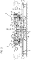
- Each table 32 further supports a pair of guide elements 38 on which protuberances 42 which project downwardly from a respective support platform 43 are slidably retained. Each of these latter is fixed to an actuator cylinder 44 having a piston 46 the free end of which is fixed to the associated table 32.
- a cam follower roller 48 projects downwardly from each support platform 43 and cooperates with a shaped cam element 50 keyed to the respective pin 28.
- the operation of the device is as follows.
- the base bodies 6 of the two slides 2 are positioned relative to the frame 4 by translational movement in two orthogonal directions.
- the second screws 26 are rotated and cooperate with the second feed nuts 24 which cause the second plates 10 to move longitudinally, these carrying the first plates 8 mounted thereon with them in their movement (this movement is indicated by the arrows 52 in Figures 1 and 3).
- the bending operation takes place thanks to a combined translational and rotational movement of the platforms 43, which support the tools 56 and the elongate elements 58, with respect to the pins 28.
- the rotation allows the desired curvature to be obtained whilst the translation, which takes place simultaneously with the rotation, causes the curved element 58 to yield so that it can no longer reassume its original, undeformed configuration as a result of the resilient restoring forces once the bending stress has been released.
- FIGS 1 to 3 of the appended drawings illustrate both types of device for enabling the radial translation mounted on the same machine. Obviously, in practice, use will be made of only one of these depending on the specific applicational requirements. In fact, the cam and cam follower roller device is more economical but requires longer to be adapted to a different bending process, whilst the actuator cylinder system (illustrated only in Figure 4) is more expensive but more rapidly adaptable to different uses.
- the apparatus of the invention may include a single slide movable on the support frame.
- Such apparatus is adapted to bending elongate elements, which can be clamped between a vice not mounted on the support structure and tools supported by the support platform of the single slide, into shapes which are not excessively complicated.
Applications Claiming Priority (3)
| Application Number | Priority Date | Filing Date | Title |
|---|---|---|---|
| ITTO920313A IT1259520B (it) | 1992-04-06 | 1992-04-06 | Struttura per il sopporto e posizionamento universali di utensili impiegati da una macchina piegatrice di elementi allungati |
| ITTO920031 | 1992-04-06 | ||
| PCT/EP1993/000813 WO1993019864A1 (en) | 1992-04-06 | 1993-04-02 | A universal support and positioning structure for tools used by an elongate element binding machine |
Publications (2)
| Publication Number | Publication Date |
|---|---|
| EP0664735A1 EP0664735A1 (en) | 1995-08-02 |
| EP0664735B1 true EP0664735B1 (en) | 1996-10-09 |
Family
ID=11410384
Family Applications (1)
| Application Number | Title | Priority Date | Filing Date |
|---|---|---|---|
| EP93908889A Expired - Lifetime EP0664735B1 (en) | 1992-04-06 | 1993-04-02 | A universal support and positioning structure for tools usable by an elongate element bending machine |
Country Status (26)
| Country | Link |
|---|---|
| US (1) | US5588322A (hu) |
| EP (1) | EP0664735B1 (hu) |
| JP (1) | JP3506702B2 (hu) |
| KR (1) | KR100250243B1 (hu) |
| AT (1) | ATE143840T1 (hu) |
| AU (1) | AU666723B2 (hu) |
| BG (1) | BG61866B1 (hu) |
| BR (1) | BR9306265A (hu) |
| CA (1) | CA2132974C (hu) |
| CZ (1) | CZ287009B6 (hu) |
| DE (1) | DE69305359T2 (hu) |
| DK (1) | DK0664735T3 (hu) |
| ES (1) | ES2094538T3 (hu) |
| FI (1) | FI108926B (hu) |
| GR (1) | GR3021856T3 (hu) |
| HU (1) | HU213555B (hu) |
| IT (1) | IT1259520B (hu) |
| NO (1) | NO301108B1 (hu) |
| NZ (1) | NZ251695A (hu) |
| PL (1) | PL171139B1 (hu) |
| RO (1) | RO111913B1 (hu) |
| RU (1) | RU2101114C1 (hu) |
| SG (1) | SG55174A1 (hu) |
| SK (1) | SK279995B6 (hu) |
| UA (1) | UA27885C2 (hu) |
| WO (1) | WO1993019864A1 (hu) |
Families Citing this family (17)
| Publication number | Priority date | Publication date | Assignee | Title |
|---|---|---|---|---|
| US5836193A (en) * | 1996-11-27 | 1998-11-17 | Aluminum Company Of America | Apparatus for forming elongated metal articles and related method |
| US6012320A (en) * | 1998-01-14 | 2000-01-11 | Oxford Suspension, Inc. | Leaf spring straightening apparatus |
| US6173599B1 (en) * | 1998-01-14 | 2001-01-16 | Oxford Suspension, Inc. | Leaf spring straightening apparatus |
| US6286352B1 (en) | 1998-12-03 | 2001-09-11 | Pullman Industries, Inc. | Stretch roll forming apparatus using frusto-conical rolls |
| US6460395B1 (en) * | 2001-05-07 | 2002-10-08 | Vought Aircraft Industries, Inc. | System and method for bending a structural member |
| US7024905B1 (en) * | 2003-04-28 | 2006-04-11 | Aaron Carlson | Portable electrical conduit pipe bending system |
| KR100978243B1 (ko) | 2007-11-06 | 2010-08-26 | 창원금속공업(주) | 트렁크리드힌지의 벤딩장치 |
| DE102010018397B4 (de) * | 2010-04-26 | 2013-12-12 | Felss Burger Gmbh | Spreizbarer Biegekopf |
| CN104998988B (zh) * | 2015-07-30 | 2017-08-18 | 东莞市文轩五金制品有限公司 | 一种自动折弯机及其生产工艺 |
| KR101972063B1 (ko) * | 2017-09-29 | 2019-04-24 | 동의대학교 산학협력단 | 벤딩기 및 벤딩공법 |
| DE102017127634A1 (de) * | 2017-11-22 | 2019-05-23 | Grob-Werke Gmbh & Co. Kg | Einheit, Einrichtung, Vorrichtung und Verfahren zum Biegen und Herstellen von Wellenwicklungen für Spulenwicklungen elektrischer Maschinen |
| IT201800009571A1 (it) * | 2018-10-18 | 2020-04-18 | Baomarc Automotive Solutions Spa | Macchina e procedimento di piegatura. |
| KR102248883B1 (ko) * | 2019-09-03 | 2021-05-06 | 주식회사 정운 | 벤딩 장치 |
| CN114558978A (zh) * | 2020-11-27 | 2022-05-31 | 台山市东扩钢构有限公司 | 一种脚踏式扣形链链节折弯装置 |
| EP4180143A1 (en) | 2021-11-16 | 2023-05-17 | Itronics S.r.l. | Apparatus and procedure for bending with stretching metallic elements |
| EP4180142A1 (en) | 2021-11-16 | 2023-05-17 | Itronics S.r.l. | Apparatus and procedure for bending with stretching metallic elements |
| EP4180144A1 (en) | 2021-11-16 | 2023-05-17 | Itronics S.r.l. | Apparatus and procedure for bending with stretching metallic elements |
Family Cites Families (6)
| Publication number | Priority date | Publication date | Assignee | Title |
|---|---|---|---|---|
| US1462315A (en) * | 1919-08-05 | 1923-07-17 | Meader R Akey | Bending machine |
| US2884987A (en) | 1956-03-30 | 1959-05-05 | Pedrick Tool And Machine Compa | Bending machines with reversible motor drive |
| FR1264229A (fr) * | 1960-07-20 | 1961-06-19 | Machine pour le cintrage d'éléments, tels que tubes, profilés ou autres | |
| DE1292617B (de) * | 1962-11-30 | 1969-04-17 | Heinrich Bartz Kg | Umrollbiegepresse |
| US4351178A (en) * | 1979-08-02 | 1982-09-28 | Hitachi, Ltd. | Apparatus for bending a straight tube into a serpentine tube |
| DE4214205A1 (de) * | 1992-04-30 | 1993-11-04 | Happich Gmbh Gebr | Vorrichtung zum biegen von profilleistenabschnitten o. dgl. |
-
1992
- 1992-04-06 IT ITTO920313A patent/IT1259520B/it active IP Right Grant
-
1993
- 1993-04-02 JP JP51710893A patent/JP3506702B2/ja not_active Expired - Fee Related
- 1993-04-02 ES ES93908889T patent/ES2094538T3/es not_active Expired - Lifetime
- 1993-04-02 AU AU39511/93A patent/AU666723B2/en not_active Ceased
- 1993-04-02 RO RO94-01617A patent/RO111913B1/ro unknown
- 1993-04-02 CZ CZ19942462A patent/CZ287009B6/cs not_active IP Right Cessation
- 1993-04-02 SK SK1196-94A patent/SK279995B6/sk not_active IP Right Cessation
- 1993-04-02 EP EP93908889A patent/EP0664735B1/en not_active Expired - Lifetime
- 1993-04-02 US US08/313,299 patent/US5588322A/en not_active Expired - Lifetime
- 1993-04-02 DE DE69305359T patent/DE69305359T2/de not_active Expired - Fee Related
- 1993-04-02 UA UA94115999A patent/UA27885C2/uk unknown
- 1993-04-02 DK DK93908889.4T patent/DK0664735T3/da active
- 1993-04-02 AT AT93908889T patent/ATE143840T1/de not_active IP Right Cessation
- 1993-04-02 WO PCT/EP1993/000813 patent/WO1993019864A1/en active IP Right Grant
- 1993-04-02 PL PL93305522A patent/PL171139B1/pl not_active IP Right Cessation
- 1993-04-02 HU HU9402782A patent/HU213555B/hu not_active IP Right Cessation
- 1993-04-02 NZ NZ251695A patent/NZ251695A/en not_active IP Right Cessation
- 1993-04-02 BR BR9306265A patent/BR9306265A/pt not_active IP Right Cessation
- 1993-04-02 CA CA002132974A patent/CA2132974C/en not_active Expired - Fee Related
- 1993-04-02 RU RU94045931A patent/RU2101114C1/ru active
- 1993-04-02 KR KR1019940703532A patent/KR100250243B1/ko not_active IP Right Cessation
-
1994
- 1994-10-04 BG BG99093A patent/BG61866B1/bg unknown
- 1994-10-05 FI FI944652A patent/FI108926B/fi active
- 1994-10-05 NO NO943722A patent/NO301108B1/no not_active IP Right Cessation
-
1996
- 1996-08-05 SG SG1996008832A patent/SG55174A1/en unknown
- 1996-12-02 GR GR960403266T patent/GR3021856T3/el unknown
Also Published As
Similar Documents
| Publication | Publication Date | Title |
|---|---|---|
| EP0664735B1 (en) | A universal support and positioning structure for tools usable by an elongate element bending machine | |
| US4901427A (en) | Punch press | |
| CN104526380B (zh) | 一种可夹持弧形板的夹具 | |
| KR890003334B1 (ko) | 밴딩장치 | |
| US5125141A (en) | Work holding apparatus | |
| CN115582786B (zh) | 一种精密机械加工平台 | |
| CN208245988U (zh) | 一种汽车管件内螺纹加工装置 | |
| CN116142812A (zh) | 夹具及加工设备 | |
| JP2719875B2 (ja) | クランプ装置 | |
| CN216912985U (zh) | 一种用于方框工件加工的快速固定夹具 | |
| CN220554856U (zh) | 一种冲压件折弯设备 | |
| JPS5930513B2 (ja) | スポット溶接機の被加工物自動送り装置 | |
| US3184949A (en) | Automatic tube bender | |
| CN216881406U (zh) | 钣金加工的工件快速矫直装置 | |
| CN220717981U (zh) | 一种齿轮加工用滚齿机 | |
| GB2141951A (en) | Drilling machine | |
| JPH0422913Y2 (hu) | ||
| JPH06155207A (ja) | クランプ装置 | |
| JPS6333925B2 (hu) | ||
| CN219703070U (zh) | 一种钣金折弯设备 | |
| CN220863318U (zh) | 一种能够翻转工件的铣床夹具 | |
| CN220593045U (zh) | 一种可移动转台带有夹紧工装的工作台 | |
| CN113799074A (zh) | 一种电气自动化夹具 | |
| CN117086835A (zh) | 一种柔性翻转装置及其使用方法 | |
| JPH0811255B2 (ja) | 多頭式曲げ装置 |
Legal Events
| Date | Code | Title | Description |
|---|---|---|---|
| PUAI | Public reference made under article 153(3) epc to a published international application that has entered the european phase |
Free format text: ORIGINAL CODE: 0009012 |
|
| 17P | Request for examination filed |
Effective date: 19940922 |
|
| AK | Designated contracting states |
Kind code of ref document: A1 Designated state(s): AT BE CH DE DK ES FR GB GR IE IT LI LU MC NL PT SE |
|
| 17Q | First examination report despatched |
Effective date: 19951012 |
|
| GRAH | Despatch of communication of intention to grant a patent |
Free format text: ORIGINAL CODE: EPIDOS IGRA |
|
| GRAH | Despatch of communication of intention to grant a patent |
Free format text: ORIGINAL CODE: EPIDOS IGRA |
|
| GRAA | (expected) grant |
Free format text: ORIGINAL CODE: 0009210 |
|
| AK | Designated contracting states |
Kind code of ref document: B1 Designated state(s): AT BE CH DE DK ES FR GB GR IE IT LI LU MC NL PT SE |
|
| REF | Corresponds to: |
Ref document number: 143840 Country of ref document: AT Date of ref document: 19961015 Kind code of ref document: T |
|
| REF | Corresponds to: |
Ref document number: 69305359 Country of ref document: DE Date of ref document: 19961114 |
|
| REG | Reference to a national code |
Ref country code: IE Ref legal event code: FG4D Free format text: 70203 |
|
| REG | Reference to a national code |
Ref country code: CH Ref legal event code: NV Representative=s name: JACOBACCI & PERANI S.A. |
|
| ITF | It: translation for a ep patent filed |
Owner name: JACOBACCI & PERANI S.P.A. |
|
| ET | Fr: translation filed | ||
| REG | Reference to a national code |
Ref country code: ES Ref legal event code: FG2A Ref document number: 2094538 Country of ref document: ES Kind code of ref document: T3 |
|
| REG | Reference to a national code |
Ref country code: PT Ref legal event code: SC4A Free format text: AVAILABILITY OF NATIONAL TRANSLATION Effective date: 19961015 |
|
| REG | Reference to a national code |
Ref country code: GR Ref legal event code: FG4A Free format text: 3021856 |
|
| REG | Reference to a national code |
Ref country code: DK Ref legal event code: T3 |
|
| PLBE | No opposition filed within time limit |
Free format text: ORIGINAL CODE: 0009261 |
|
| STAA | Information on the status of an ep patent application or granted ep patent |
Free format text: STATUS: NO OPPOSITION FILED WITHIN TIME LIMIT |
|
| 26N | No opposition filed | ||
| REG | Reference to a national code |
Ref country code: GB Ref legal event code: IF02 |
|
| PGFP | Annual fee paid to national office [announced via postgrant information from national office to epo] |
Ref country code: ES Payment date: 20090227 Year of fee payment: 17 |
|
| PGFP | Annual fee paid to national office [announced via postgrant information from national office to epo] |
Ref country code: PT Payment date: 20090323 Year of fee payment: 17 |
|
| PGFP | Annual fee paid to national office [announced via postgrant information from national office to epo] |
Ref country code: CH Payment date: 20090226 Year of fee payment: 17 |
|
| PGFP | Annual fee paid to national office [announced via postgrant information from national office to epo] |
Ref country code: MC Payment date: 20090416 Year of fee payment: 17 Ref country code: IE Payment date: 20090421 Year of fee payment: 17 Ref country code: DK Payment date: 20090415 Year of fee payment: 17 |
|
| PGFP | Annual fee paid to national office [announced via postgrant information from national office to epo] |
Ref country code: SE Payment date: 20090424 Year of fee payment: 17 Ref country code: NL Payment date: 20090415 Year of fee payment: 17 Ref country code: LU Payment date: 20090414 Year of fee payment: 17 Ref country code: IT Payment date: 20090424 Year of fee payment: 17 Ref country code: FR Payment date: 20090430 Year of fee payment: 17 Ref country code: DE Payment date: 20090422 Year of fee payment: 17 Ref country code: AT Payment date: 20090416 Year of fee payment: 17 |
|
| PGFP | Annual fee paid to national office [announced via postgrant information from national office to epo] |
Ref country code: BE Payment date: 20090528 Year of fee payment: 17 |
|
| PGFP | Annual fee paid to national office [announced via postgrant information from national office to epo] |
Ref country code: GR Payment date: 20090427 Year of fee payment: 17 Ref country code: GB Payment date: 20090421 Year of fee payment: 17 |
|
| BERE | Be: lapsed |
Owner name: *BENDING TOOLING S.R.L. Effective date: 20100430 |
|
| REG | Reference to a national code |
Ref country code: NL Ref legal event code: V1 Effective date: 20101101 |
|
| EUG | Se: european patent has lapsed | ||
| PG25 | Lapsed in a contracting state [announced via postgrant information from national office to epo] |
Ref country code: MC Free format text: LAPSE BECAUSE OF NON-PAYMENT OF DUE FEES Effective date: 20100430 |
|
| REG | Reference to a national code |
Ref country code: CH Ref legal event code: PL |
|
| REG | Reference to a national code |
Ref country code: DK Ref legal event code: EBP |
|
| GBPC | Gb: european patent ceased through non-payment of renewal fee |
Effective date: 20100402 |
|
| REG | Reference to a national code |
Ref country code: IE Ref legal event code: MM4A |
|
| REG | Reference to a national code |
Ref country code: FR Ref legal event code: ST Effective date: 20101230 |
|
| PG25 | Lapsed in a contracting state [announced via postgrant information from national office to epo] |
Ref country code: NL Free format text: LAPSE BECAUSE OF NON-PAYMENT OF DUE FEES Effective date: 20101101 Ref country code: IE Free format text: LAPSE BECAUSE OF NON-PAYMENT OF DUE FEES Effective date: 20100402 Ref country code: AT Free format text: LAPSE BECAUSE OF NON-PAYMENT OF DUE FEES Effective date: 20100402 |
|
| PG25 | Lapsed in a contracting state [announced via postgrant information from national office to epo] |
Ref country code: PT Free format text: LAPSE BECAUSE OF NON-PAYMENT OF DUE FEES Effective date: 20101004 Ref country code: LI Free format text: LAPSE BECAUSE OF NON-PAYMENT OF DUE FEES Effective date: 20100430 Ref country code: DE Free format text: LAPSE BECAUSE OF NON-PAYMENT OF DUE FEES Effective date: 20101103 Ref country code: CH Free format text: LAPSE BECAUSE OF NON-PAYMENT OF DUE FEES Effective date: 20100430 |
|
| PG25 | Lapsed in a contracting state [announced via postgrant information from national office to epo] |
Ref country code: GB Free format text: LAPSE BECAUSE OF NON-PAYMENT OF DUE FEES Effective date: 20100402 Ref country code: IT Free format text: LAPSE BECAUSE OF NON-PAYMENT OF DUE FEES Effective date: 20100402 Ref country code: BE Free format text: LAPSE BECAUSE OF NON-PAYMENT OF DUE FEES Effective date: 20100430 Ref country code: GR Free format text: LAPSE BECAUSE OF NON-PAYMENT OF DUE FEES Effective date: 20101103 |
|
| PG25 | Lapsed in a contracting state [announced via postgrant information from national office to epo] |
Ref country code: DK Free format text: LAPSE BECAUSE OF NON-PAYMENT OF DUE FEES Effective date: 20100503 |
|
| REG | Reference to a national code |
Ref country code: ES Ref legal event code: FD2A Effective date: 20110715 |
|
| PG25 | Lapsed in a contracting state [announced via postgrant information from national office to epo] |
Ref country code: ES Free format text: LAPSE BECAUSE OF NON-PAYMENT OF DUE FEES Effective date: 20110705 |
|
| PG25 | Lapsed in a contracting state [announced via postgrant information from national office to epo] |
Ref country code: ES Free format text: LAPSE BECAUSE OF NON-PAYMENT OF DUE FEES Effective date: 20100403 |
|
| PG25 | Lapsed in a contracting state [announced via postgrant information from national office to epo] |
Ref country code: FR Free format text: LAPSE BECAUSE OF NON-PAYMENT OF DUE FEES Effective date: 20100430 |
|
| PG25 | Lapsed in a contracting state [announced via postgrant information from national office to epo] |
Ref country code: LU Free format text: LAPSE BECAUSE OF NON-PAYMENT OF DUE FEES Effective date: 20100402 Ref country code: SE Free format text: LAPSE BECAUSE OF NON-PAYMENT OF DUE FEES Effective date: 20100403 |