EP0660998B1 - Angelwinde - Google Patents
Angelwinde Download PDFInfo
- Publication number
- EP0660998B1 EP0660998B1 EP94120714A EP94120714A EP0660998B1 EP 0660998 B1 EP0660998 B1 EP 0660998B1 EP 94120714 A EP94120714 A EP 94120714A EP 94120714 A EP94120714 A EP 94120714A EP 0660998 B1 EP0660998 B1 EP 0660998B1
- Authority
- EP
- European Patent Office
- Prior art keywords
- restrainer
- spool
- fishing
- rotor
- spinning reel
- Prior art date
- Legal status (The legal status is an assumption and is not a legal conclusion. Google has not performed a legal analysis and makes no representation as to the accuracy of the status listed.)
- Expired - Lifetime
Links
- 238000009987 spinning Methods 0.000 title claims description 92
- 239000000837 restrainer Substances 0.000 claims description 276
- 230000013011 mating Effects 0.000 description 25
- 238000004804 winding Methods 0.000 description 22
- 230000002093 peripheral effect Effects 0.000 description 17
- 230000000452 restraining effect Effects 0.000 description 9
- 230000004048 modification Effects 0.000 description 7
- 238000012986 modification Methods 0.000 description 7
- 230000036961 partial effect Effects 0.000 description 6
- 239000004576 sand Substances 0.000 description 6
- 230000000694 effects Effects 0.000 description 3
- 239000004033 plastic Substances 0.000 description 3
- 239000013535 sea water Substances 0.000 description 3
- 230000003466 anti-cipated effect Effects 0.000 description 2
- 230000001771 impaired effect Effects 0.000 description 2
- 241000251468 Actinopterygii Species 0.000 description 1
- 241000276420 Lophius piscatorius Species 0.000 description 1
- 230000001419 dependent effect Effects 0.000 description 1
- 239000000428 dust Substances 0.000 description 1
- 230000002829 reductive effect Effects 0.000 description 1
- 230000000717 retained effect Effects 0.000 description 1
- 230000002441 reversible effect Effects 0.000 description 1
Images


Classifications
-
- A—HUMAN NECESSITIES
- A01—AGRICULTURE; FORESTRY; ANIMAL HUSBANDRY; HUNTING; TRAPPING; FISHING
- A01K—ANIMAL HUSBANDRY; AVICULTURE; APICULTURE; PISCICULTURE; FISHING; REARING OR BREEDING ANIMALS, NOT OTHERWISE PROVIDED FOR; NEW BREEDS OF ANIMALS
- A01K89/00—Reels
- A01K89/01—Reels with pick-up, i.e. with the guiding member rotating and the spool not rotating during normal retrieval of the line
- A01K89/01121—Frame details
- A01K89/011221—Frame details with line or water shields
-
- A—HUMAN NECESSITIES
- A01—AGRICULTURE; FORESTRY; ANIMAL HUSBANDRY; HUNTING; TRAPPING; FISHING
- A01K—ANIMAL HUSBANDRY; AVICULTURE; APICULTURE; PISCICULTURE; FISHING; REARING OR BREEDING ANIMALS, NOT OTHERWISE PROVIDED FOR; NEW BREEDS OF ANIMALS
- A01K89/00—Reels
- A01K89/01—Reels with pick-up, i.e. with the guiding member rotating and the spool not rotating during normal retrieval of the line
- A01K89/0108—Pick-up details
-
- A—HUMAN NECESSITIES
- A01—AGRICULTURE; FORESTRY; ANIMAL HUSBANDRY; HUNTING; TRAPPING; FISHING
- A01K—ANIMAL HUSBANDRY; AVICULTURE; APICULTURE; PISCICULTURE; FISHING; REARING OR BREEDING ANIMALS, NOT OTHERWISE PROVIDED FOR; NEW BREEDS OF ANIMALS
- A01K89/00—Reels
- A01K89/01—Reels with pick-up, i.e. with the guiding member rotating and the spool not rotating during normal retrieval of the line
- A01K89/0111—Spool details
Definitions
- the present invention relates to a spinning reel for fishing which is capable of preventing a fishing line from being caught in a clearance between a rotor and a spool.
- a typical spinning reel for fishing is arranged, as shown in Fig. 25, such that a semi-annular bail 5 can be reversibly set at either one of a fishing-line winding position (A side in Fig. 25) and a fishing-line releasing position (B side in Fig. 25), the bail being mounted, via bail support members, e.g, a bail arm 9 with a line roller 7 and a bail holder (not shown), onto forward ends of a pair of bail support arms 3 provided on both sides of a rotor 1, respectively.
- bail support members e.g, a bail arm 9 with a line roller 7 and a bail holder (not shown)
- the bail 5 is first brought down to the fishing-line winding position as shown in Fig. 25, and then the rotor 1 is rotated in the winding direction by turning a manually operated handle 13 provided on a reel body 11, whereby a fishing line is wound onto a spool 15 making the longitudinal reciprocating motion linking with the rotation of the rotor 1.
- reference numeral 17 denotes a mounting leg integrally formed with the reel body 11.
- the so-called "undesirable line catch” may occur that the fishing line enters a clearance between the spool 15 and the rotor 1 due to tensional fluctuation, twisting of the fishing line and the like when the fishing line is wound up, and the fishing line is wound onto and caught by a spool shaft (not shown) of the spool 15.
- a spinning reel for fishing which is provided with a fishing-line entry restrainer as disclosed in Japanese Utility Model Kokoku Publication No. Hei. 3-9656.
- Figs. 26 and 27 show such a spinning reel, in which a fishing-line entry restrainer 25 is fitted on a spool shaft 27 in a spool 23 so that the fishing-line entry restrainer 25 longitudinally moves together with the spool 23 along bail support arms 21 while rotating together with a rotor 19.
- reference numeral 29 denotes restraining portions of the fishing-line entry restrainer 25, the restraining portions being provided with, at its forward end, mating portions 31 which mate with the respective bail support arms 21.
- This type of the spinning reel still has the following disadvantage: It is known that when the fishing line is wound up upon hitting of the fish, the bail support arms are deformed inwardly if a great load is applied to the fishing line. Thus, in the arrangement in which the fishing-line entry restrainer 25 in combination with the spool 23 is moved back and forth along the bail support arms 21, the deformation of the bail support arms 21 hinders the fishing-line entry restrainer 25 from smoothly moving. In case where, for example, the reel is accidentally dropped with the result that the bail support arms 21 are plastically deformed or where sea water, sand, dust or the like happens to stick to the bail support arms 21, the fishing-line entry restrainer 25 will not move smoothly. Consequently, the longitudinal movement of the spool 23 incorporating the fishing-line entry restrainer 25 and the rotation of the rotor 19 will be impaired, and the fishing line cannot be wound up or drawn out smoothly.
- FR-A-988893 discloses a spinning reel for fishing comprising a rotor which is rotatably mounted on a reel body, a spool which is supported to the reel body via a spool shaft, such that the spool is reciprocable in an axial direction of the spool shaft as the fishing-line is being wound on the spool when the rotor is rotated by a handle.
- the spinning reel for fishing according to this prior art document, furthermore, comprises a fishing-line entry restrainer which is rotatably mounted on the inner face of the spool as well as rotatably on the spool shaft.
- the fishing-line entry restrainer is fixed to the spool shaft by a ring serving as follow-up means which causes the fishing-line entry restrainer to move with the spool.
- An object of the present invention is to provide a spinning reel for fishing which is capable of preventing the undesirable line catch without causing any trouble to the operation of winding or releasing the fishing line.
- Figs. 1 through 4 show a first embodiment of a spinning reel for fishing according to the present invention.
- reference numeral 33 denotes a rotor rotatably provided on the leading end of a reel body 35.
- a pair of bail support arms 37 are integrally molded into the rotor 33 on both the respective rear sides thereof and a semi-annular bail 39 is provided to the leading end of the bail support arm 37 via a bail arm 41 furnished with a line roller 40 and a bail holder 43, the semi-annular bail 39 being set reversible from a fishing-line winding position to a fishing-line releasing position and vice versa.
- reference numeral 45 denotes a spool arranged concentrically with respect to the rotor 33 and supported with a spool shaft 47 which is supported onto the reel body 35 in such a way that it is capable of making a reciprocating motion in an axial direction thereof.
- This embodiment is characterized in that a fishing-line entry restrainer (hereinafter called the "restrainer") 53 for restraining the fishing line from being caught by the spool shaft 47 is installed in between the spool 45 and the cylindrical portion 51 of the rotor 33, which cylindrical portion is generally located within the spool 45.
- a fishing-line entry restrainer hereinafter called the "restrainer” 53 for restraining the fishing line from being caught by the spool shaft 47 is installed in between the spool 45 and the cylindrical portion 51 of the rotor 33, which cylindrical portion is generally located within the spool 45.
- the restrainer 53 is provided with a C-shaped resin-molded annular member 55, and four stays 57 integral with and extended rearwardly from the outer peripheral edge of the annular member 55.
- the stays 57 in each adjacent pair are arranged at an angular interval of 90°.
- the annular member 55 is movably fitted on the outer periphery of a cylindrical portion 59 which is located inside the spool 45 and concentric to the spool shaft 47.
- An O-ring is provided on the outer periphery of the rotor-side end of the cylindrical portion 59 to form a retaining portion 61 circumscribing the rotor-side end.
- the retaining portion 61 When the spool 45 is moved forward by turning the manually operated handle 49, the retaining portion 61 is brought into engagement with the inner peripheral edge 55a of the annular member 55 as shown in Fig. 4, and thus it functions as a follow-up means for making the restrainer 53 follow the spool moving forward.
- the cylindrical portion 51 of the rotor 33 is provided with guide slots 65 which extends in the axial direction of the spool shaft 47.
- Each of the leading ends of the stays 57 is inwardly bent into L-shape to form an engagement portion 63 which movably engages with the corresponding guide slot 65.
- the restrainer 53 moves along the guide slots 65 while rotating together with the rotor 33 in this embodiment.
- the stays 57 extend across the gap between the cylindrical portion 51 and the cylindrical portion 59 as shown in Fig. 4 so as to prevent the fishing line from being caught by the spool shaft 47.
- the restrainer 53 is pushed back to the original position as the spool 45 is moved back as shown in Fig. 3.
- the fishing line is wound onto the spool 45 making the reciprocating motion linking with the rotation of the rotor 33 when the manually operated handle 49 is operated to rotate the rotor 33 after the bail 39 is brought down toward the fishing-line winding position.
- the forward motion of the spool 45 causes the retaining portion 61 to engage with the inner peripheral edge 55a of the annular portion 55, to thereby move, in the same direction, the restrainer 53 rotating together with the rotor 33.
- the restrainer 53 rotating together with the rotor 33 is pushed back to the original position shown in Fig. 3.
- the length of the stays 57 is set so that the stays 57 extend across the gap between the leading end of the cylindrical portion 51 and the rear end of the cylindrical portion 59 when the spool 45 is located at the foremost position. Consequently, it is possible to avoid the increase of the entire weight of the reel even when the stroke of the spinning reel is lengthened.
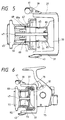
- Fig. 5 shows a second embodiment of the spinning reel for fishing according to the present invention.
- the retaining portion 61 provided on the cylindrical portion 59 of the spool 45 engages with the inner peripheral edge 55a of the annular portion 55 so as to move the restrainer 53 in the same direction.
- This arrangement may be modified, as in the second embodiment, such that stays 57 are extended rearwardly from the inner peripheral edges of an annular portion 69.
- a restrainer 67 includes a C-shaped resin-molded annular portion 69, and four stays 57 integral with and extended from the inner peripheral edge of the annular member 69.
- the four stays 57 in the each adjacent pair are arranged at an angular interval of 90°.
- the annular portion 69 is movably fitted on the inner periphery of the spool 45, and an O-ring is provided on the inner periphery of the spool 45 to form a retaining portion 71 circumscribing the inner periphery of the spool 45.
- the retaining portion 71 is brought into engagement with the outer peripheral edge 69a of the annular portion 69 to cause the restrainer 67 to follow the spool 45 in the same direction.
- Figs. 6 through 8 show a third embodiment of the spinning reel for fishing according to the present invention, wherein a restrainer in a cylindrical form in place of the restrainer 53 is fitted in between the spool and the rotor.
- reference numeral 73 denotes a rotor rotatably fitted to a reel body 75; and 77, a spool supported with the spool shaft 47.
- a fishing line is wound on the spool 77 as the rotor 73 rotates.
- the spool 77 in this embodiment has no cylindrical portion 59 like what is shown in the first embodiment.
- reference numeral 79 denotes a cylindrical resin-molded restrainer substantially similar in configuration to the inner wall of the spool 77 and as shown therein, the restrainer 79 is placed along the inner periphery of the spool 77 and in between the inner periphery of the spool 77 and the cylindrical base portion 81 of the rotor 73. The rear end of the restrainer 79 is extended up to the base side of the bail support arms 37.
- a pair of retaining members 83 are outwardly projected from the forward open edge of the restrainer 79 and arranged at an angular interval of 180° intervals.
- An annular retaining portion 85 for retaining the retaining portions 83 is inwardly projected from the inner periphery of the spool 77 so as to move the restrainer 79 forward when the spool 77 is moved forward by turning the manually operated handle, which will be explained later in more detail.
- the cylindrical base portion 81 of the rotor 73 is, as shown in Figs. 7 and 8, formed with guide grooves 89 in the axial direction of the spool shaft 47, so that mating portions 87 inwardly provided at the rear end open edge of the restrainer 79 and arranged at an angular interval of 180° movably engage with the respective guide grooves 89.
- the manually operated handle is turned to cause the spool 77 moving forward to move the restrainer 79 forward, the restrainer 79 rotating together with the rotor 73 moves along the guide grooves 89, and when the spool 77 is completely extended as shown in Fig.
- the restrainer 79 extends across the gap between the cylindrical base portion 81 and the inner periphery of the spool 77, whereby a fishing line is prevented from being wound on the spool shaft 47. Then the restrainer 79 is pushed back to the original position as shown in Fig. 6 as the spool 77 is moved back.
- the spool 77 makes the reciprocating motion while the fishing line is being wound up thereon, and when the spool 77 moves forward as shown in Fig. 7, the retaining portion 85 on the spool side 77 is brought into engagement with the retaining portions 83 of the restrainer 79 rotating together with the rotor 73 to cause the restrainer 79 to move in the same direction.
- the restrainer 79 rotating together with the rotor 73 is pushed back to the original position of Fig. 6.
- the restrainer 79 extends across the gap between the inner periphery of the spool 77 and the cylindrical base portion 81 of the rotor 73 to prevent the fishing line from being caught by the spool shaft 47 as shown in Figs. 6 and 7.
- the restrainer 79 in this embodiment is allowed to smoothly move back and forth without being affected by the deformation of the bail support arm 37, the sticking of sand thereto and the like. Therefore, the movements of the spool 77 and the rotor 73 are made free from any trouble.
- the spool 77 is moved up to the forward endmost side as shown in Fig. 7, there is substantially no possibility that the weight of the whole reel may increase even when the stroke of the spinning reel is lengthened since it is only needed to adapt the restrainer 79 in such a way as to extend across the gap between the inner periphery of the spool 77 and the leading end of the cylindrical portion 81.
- Fig. 9 shows a fourth embodiment of the spinning reel for fishing according to the present invention, which is a modification of the third embodiment.
- the guide grooves 89 are formed in the cylindrical base portion 81 of the rotor 73 and the mating portions 87 of the restrainer 79 engage therewith so that the restrainer 79 rotates in linking with the rotation of the rotor 73.
- the restrainer 79 need not be rotated together with the rotor, however.
- the guide grooves 89 of the third embodiment are dispensed with in the fourth embodiment. That is to say, instead of providing the guide grooves 89 on the outer periphery 81 of the rotor 73, the mating portions 87 are simply set on the cylindrical base portion 81 freely movably in this embodiment as shown in Fig. 9. In this case, the restrainer 79 is movably fitted to the cylindrical base portion 81, so that the rotational torque of the rotor 73 is not transmitted to the restrainer 79.
- the restrainer 79 extending across the gap between the inner periphery of the spool 77 and the cylindrical base portion 81 of the rotor 73 prevents the fishing line from being caught by the spool shaft 47 likewise as in the embodiment shown in Fig. 7.
- the fishing line is also prevented from being caught by the spool shaft 47 without any trouble to the operation of winding or releasing the fishing line in this embodiment. Moreover, there is no possibility that the weight of the whole reel may increase even when the stroke of a spinning reel is lengthened.
- Fig. 10 shows a fifth embodiment of the spinning reel for fishing according to the present invention.
- the retaining portion 85 for moving the restrainer 79 is provided on the inner periphery of the spool 77 in the third embodiment, it is characterized in this embodiment that the retaining portion for moving the restrainer is provided on the spool shaft instead of the spool.
- reference numeral 91 denotes a closed-end restrainer substantially in a cup-shape, that has been resin-molded into substantially the same profile as the inside of the spool 77, and the restrainer 91 is placed along the inner periphery of the spool and in between the spool 77 and the cylindrical base portion 81 of the rotor 73. Further, the rear end of the restrainer 91 is extended up to the base of the bail support arms 37 and there are formed, at the rearward open edge of the restrainer 91, mating portions 87 which engage with the respective guide grooves 89 provided on the outer periphery of the cylindrical base portion 81 of the rotor 73. The mating portions 87 are arranged at an angular interval of 180°. By means of the mating portion 87 and the guide grooves 89, the restrainer 91 rotates together with the rotor 73 when the fishing line is wound up.
- a spool shaft 93 for supporting the spool 77 is passed through the center of the restrainer 91 and includes a small diameter portion 93a passing through the restrainer 91 and a large diameter portion 93b on the rotor side 73.
- a stepped portion where the small diameter portion 93a meets with the large diameter portion 93b functions as a retaining portion 95 for causing the restrainer 91 to move in the same direction.
- the restrainer 79 extending across the gap between the spool shaft 93 and the cylindrical base portion 81 of the rotor 73 prevents the fishing line from being caught by the spool shaft 47.
- Figs. 11 and 12 show a sixth embodiment of the spinning reel for fishing according to the present invention.
- reference numeral 97 denotes a spool supported by the spool shaft 47; and 99, a rotor.
- the longitudinal reciprocating motion of the spool 97 is made in linking with the rotation of the rotor 99.
- retaining portions 101 are formed at the rear end peripheral edge of the spool 97 to protrude radially outwardly, and a restrainer 103 is retained by the retaining portions 101 by means of retaining portions 105.
- the restrainer 103 is a plate-like plastic member fitted onto the cylindrical portion 107 of the rotor 99, and is formed with mating portions 111 which engage with respective guide grooves 109 provided, at an angular interval of 180°, in the outer periphery of the cylindrical portion 107.
- the mating portions 111 are movable in the axial direction of the spool shaft 47 along the guide grooves 109.
- the retaining portions 105 respectively located on both sides of the restrainer 103 is kept in engagement with the retaining portion 101 of the spool 97 as noted previously, so that the restrainer 103 is coupled to the spool 97 to reciprocate together with the spool 97.
- the restrainer 103 is allowed to reciprocate together with the rotor 99 when the spool 99 longitudinally reciprocates as the fishing line is wound up.
- the restraining projections 113 of the restrainer 103 prevent the fishing line trying to enter the gap between the bail support arms 37 and the spool 97 due to tensional fluctuation and the twisting of the fishing line from being caught by the spool shaft 47.
- the restrainer 103 is not only lighter than those described by reference to the preceding embodiments but also capable of restraining the fishing line at a more preferable position.
- the provision of the elastic restraining projections 113 on the restrainer 103 can permit the deformation of the support arms 37 without causing any trouble in operation. That is to say, even though the support arms 37 is deformed due to the large load in winding the fishline onto the spool 97, the elastic restraining projections 113 contacting the support arms 37 absorb such deformation of the support arms 37 to make the operation of the restrainer 103 free from such deformation.
- Figs. 13 and 14 show a seventh embodiment of the spinning reel according to the present invention, which is characterized in that a spring member, in place of the retaining portion 85 of Fig. 6, is employed as a means for making a restrainer follow the movement of a spool.
- reference numeral 115 denotes a restrainer which is similar to the restrainer 79 of Fig. 6 and formed into substantially the same profile as the inside of a spool 117.
- the restrainer 115 is placed along the inner periphery of the spool 117 and in between the spool 117 and the cylindrical base portion 81 of the rotor 73, the rear end of the restrainer 115 being extended up to the base of the bail support arms 37.
- mating portions 119 for engaging with the respective guide grooves 89 of the rotor 73 are provided at the rear end open edge of the restrainer 115, the mating portions 119 being projected radially inwardly and arranged at the 180° interval.
- an annular spring holding portion 121 centering around the spool shaft 47 is projected axially inwardly (i.e. toward the rotor 73) at the forward open edge of the restrainer 115.
- a coil spring 123 for consistently urging the restrainer 115 away from the rotor 73 and forcing it to contact the spool 117 is extended along the spool shaft 47 and interposed between a spring holding member 121 and the rotor 73.
- the restrainer 115 moves in the same direction by the force of the coil spring while it rotates together with the rotor 73.
- the restrainer 115 extends across the gap between the cylindrical base portion 81 and the inner periphery of the spool 117 when the spool 117 is moved up to the forward end, and prevents the fishing line from being caught by the spool shaft 47.
- the restrainer 115 is pushed back to the original position against the urging force of the coil spring 123.
- the fishing line is wound on the spool 117 making the reciprocating motion linking with the rotation of the rotor 73 by turning the manually operated handle 49 after the bail 39 is brought down toward the fishing-line winding position.
- the restrainer 115 follows the movement of the spool 117 and moves in the same direction because of the force of the coil spring 123 while rotating together with the rotor 73.
- the restrainer 115 is pushed back to the original position against the force of the coil spring 123.
- the restrainer 115 extends across the gap between the cylindrical base portion 81 and the inner periphery of the spool 117 and prevents the fishing line from being caught by the spool shaft 47. Moreover, the coil spring 123 keeps forcing the restrainer 115 to contact the spool 117, thus positively preventing the restrainer 115 from clattering during the fishing operation.
- the fishing line is also prevented from being caught by the spool shaft 47 without causing any trouble to the operation of winding or releasing the fishing line in this embodiment. Moreover, it is possible to prevent the increase of the weight of the whole reel even when the stroke of a spinning reel is lengthened. In addition to the above effects, another advantage is that noise generated by the clattering of the restrainer 115 can be obviated.
- a further acceptable arrangement is, as shown in Fig. 15 illustrating an eighth embodiment of the present invention, to provide a plurality of retaining projections 124 on the rear end outer periphery of the cylindrical portion 117a of a spool in such a way that the retaining projections 124 are formed integrally or separately at appropriate intervals in the circumferential direction, or otherwise annularly over the whole outer periphery thereof.
- Figs. 16 through 18 show a ninth embodiment of the spinning reel according to the present invention, which is characterized in that a spring member, in place of the retaining portion 95 of Fig. 10, is employed as a means for making a restrainer follow the movement of a spool likewise and that the profiles of the restrainer and the spool are slightly altered in this embodiment.
- reference numeral 125 denotes a spool supported by a spool shaft 127 and concentric to a rotor 129; and 131, a closed-end restrainer that has been molded substantially into the same profile as the inside of the spool 125 and is placed along the inner periphery of the spool 125 between the spool 125 and the cylindrical base portion 133 of the rotor 129.
- mating portions 137 for engaging with respective guide grooves 135 arranged in the cylindrical base portion 133 of the rotor 129 are provided at the rear end open edge of the restrainer 131 extended up to the base of the bail support arms 37, the mating members 137 being projected radially inwardly and arranged at the 180° interval.
- the spool shaft 127 is passed through the center of the leading-end side of the restrainer 131, and annular spring holding portions 139 and 141 centering around the spool shaft 127 are respectively formed on the forward inner face of the restrainer 131 and the rotor 129 located opposite thereto.
- the coil spring 123 for consistently urging the restrainer 131 and forcing it to contact the spool 125 is stretched in between the spring holding members 139 and 141.
- the restrainer 131 When the spool 125 is moved up to the forward endmost side as shown in Fig. 17, the restrainer 131 extends across the gap between the cylindrical base portion 133 of the rotor 129 and the inner periphery of the spool 125 so as to prevent the fishing line from being caught by the spool shaft 127. Then the restrainer 131 is pushed back to the original position against the force of the coil spring 123 as the spool 125 is moved back.
- the above arrangement in this embodiment further includes a plurality of projections 143 provided on the outer periphery of the restrainer 131 so as to restrain the entry of the fishing line.
- Fig. 18 is a sectional view taken along line 18-18 of Fig. 17, wherein reference numeral 145 denotes cutouts or notches formed in the rear end peripheral edge 125a of the spool 125, the cutouts respectively corresponding to the projections 143.
- the restrainer 131 is inserted into the inside of the spool 125 such that the projections 143 into each cutout 145.
- the rear end peripheral edge 125a of the spool 125 is inwardly tilted, and consequently, this inwardly tilting configuration of the rear end peripheral edge 125a can permit an angler to easily pull up the fishing line that has been displaced to the rear end peripheral edge 125a to the fishing-line winding portion 125b of the spool 125.
- the restrainer 131 is caused to follow the spool 125. That is, when the latter is moved forward, the restrainer 131, while rotating together with the rotor 129, moves in the same direction because of the force of the coil spring 123. When the spool 125 is moved back, on the other hand, the restrainer 131 is pushed back to the original position against the force of the coil spring 123.
- the restrainer 131 extends across the gap between the cylindrical portion 133 and the inner periphery of the spool 125 and prevents the fishing line from being caught by the spool shaft 127. Further, each of the projections 143 on the outer periphery of the restrainer 131 also prevents the fishing line from advancing toward the spool shaft 127. Moreover, the coil spring 123 keeps forcing the restrainer 131 to contact the spool 125, thus preventing the restrainer 131 from clattering during the fishing operation.
- the fishing line is also prevented from being caught by the spool shaft 127 without causing any trouble to the operation of winding or releasing the fishing line and noise generated due to the clattering of the restrainer 131 can be obviated likewise in this embodiment.
- This embodiment is advantageous in that since the rear end peripheral edge 125a of the spool 125 is inwardly tilted, the fishing line that has been fallen to the rear end peripheral edge 125a can easily be pulled up to the fishing-line winding portion 125b of the spool 125 by making use of its configuration.
- annular recess 147 for retaining the fishing line may be formed on the outer periphery of the restrainer 131 as shown in Fig. 19 to make the restrainer 131 together with the annular recesses 147 restrain the entry of the fishing line toward the spool shaft 127.
- a rubber ring 149 with a plurality of projections 149a outwardly projected therefrom instead of the projections 143, may be fitted to the outer periphery of the restrainer 131 to restrain the entry of the fishing line toward the spool shaft 127 as shown in Figs. 20 and 21.
- Fig. 22 shows a tenth embodiment of a spinning reel for fishing according to the present invention, wherein the restrainer 131 shown in Fig. 16 is made up of separatable two elements, i.e. a restrainer base fitted to the cylindrical base portion of the rotor and a movable restrainer member which is longitudinally movably mounted to the restrainer base.
- the restrainer 131 shown in Fig. 16 is made up of separatable two elements, i.e. a restrainer base fitted to the cylindrical base portion of the rotor and a movable restrainer member which is longitudinally movably mounted to the restrainer base.
- reference numeral 151 denotes a restrainer placed along the inner periphery of the spool 125 and in between the spool 125 and the cylindrical base portion 155 of a rotor 153.
- the restrainer 151 comprises a restrainer base 151a secured to the cylindrical base portion 155 of the rotor 153 with machine screws and a bowl-shaped movable restrainer member 151b which is urged by the coil spring 123 to the spool 125.
- the restrainer base 151a is formed with guide slots 159 extending in the axial direction of the spool shaft 127, and the movable restrainer member 151b is provided with mating portions 157 at the rear end peripheral edge of the movable restrainer member 151b and at the angular interval of 90°, the mating portions 157 movably engaging with the respective guide slots 159.
- the movable restrainer member 151b moves in the same direction because of the force of the coil spring 123 while the restrainer 151 rotates together with the rotor 153.
- the restrainer base 151a and movable restrainer member 151b of the restrainer 151 extend across the gap between the rotor 153 and the inner periphery of the spool 125 to prevent the fishing line from being caught by the spool shaft 127.
- the movable restrainer member 151b is pushed back to the original position against the force of the coil spring 123.
- the restrainer 151 prevents the fishing line from being caught by the spool shaft 127 as in the preceding embodiments. Moreover, the coil spring 123 keeps forcing the movable restrainer member 151b to contact the spool 125, thus preventing the restrainer 151 from clattering during the fishing operation.
- the fishing line is also prevented from being caught by the spool shaft 127 without causing any trouble to the operation of winding or releasing the fishing line and noise generated due to the clattering of the restrainer 131 can be prevented likewise in this embodiment. Further, the fishing line that has been fallen to the rear end peripheral edge 125a can easily be pulled up to the fishing-line winding portion 125b of the spool 125 by making use of its configuration.
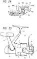
- Figs. 23 and 24 show an eleventh embodiment of the present invention, which is a modification of the tenth embodiment shown in Fig. 22.
- an annular mating groove 161 is provided on the outer periphery of the cylindrical base portion 155 of the rotor 153, instead of securing the restrainer base 151a to the rotor 153 with machine screws, and mating projections 163, which engage with the mating grooves 161, are provided on the restrainer base 151a, so that the restrainer base 151a may be attached to the rotor 153 instantly in the simple operation.
- like reference characters are given to like component parts in the embodiment shown in Fig. 22 and the description thereof will be omitted.
- the restrainer 151 also prevents the fishing line from being caught by the spool shaft 127 and the coil spring 123 keeps forcing the movable restrainer member 151b to contact the spool 125, whereby the intended purpose can be accomplished likewise as in the embodiment of Fig. 22.
- coil spring 123 has been used as a means for making the movable restrainer member 151b follow the movement of the spool 125 in the embodiments of Figs. 22 through 24, any means such as the retaining portion 85 of Fig. 7, for embodiment, may be employed in place of the coil spring 123.
- Figs. 28, 29 and 30 show a spinning reel for fishing according to a twelfth embodiment of the present invention.
- a fishing-line entry restrainer 251 for preventing the fishing line from being caught by the spool shaft 247 is fitted between the spool 204 and the cylindrical portion 249 of the rotor 233.
- the restrainer 251 is a closed-end plastic cylindrical body substantially similar in configuration to the inside of the skirt portion 245a of the spool 245 and its rear end is extended up the base of bail support arms 237.
- the spool shaft 247 is passed through the center of the restrainer 251.
- the spool shaft 247 is formed with a small diameter portion 247a passed through the restrainer 251 and a large diameter portion 247b on the side of the rotor 233, so that the stepped portion where the small and large diameter portions 247a and 247b meet functions as a retaining portion 253 for making the restrainer 251 follow the spool 245 being moved forward.
- guide grooves 255 for guiding the restrainer 251 along the spool shaft 247 when the restrainer 251 is moved are provided at an angular interval of 180° on the inner periphery of the skirt portion 245a of the spool 245.
- Mating portions 257 provided on the outer periphery of the restrainer 251 are made to slidably engage with the respective guide grooves 255.
- the restrainer 251 extends across the gap between the cylindrical portion 249 of the rotor 233 and the inner periphery of the skirt portion 245a of the spool 245 when the spool 245 is moved up to the forward end so as to prevent the fishing line from being caught by the spool shaft 247.
- the spinning reel for fishing in this embodiment is provided with a coil spring 259 between the spool 245 and the restrainer 251 to prevent the restrainer 251 from clattering during the fishing operation.
- annular spring holding portions 261 and 263 both centering around the spool shaft 247 are formed on the leading-end inner face of the spool 245 and the leading-end surface of the restrainer 251, respectively
- the coil spring 259 which keeps urging the restrainer 251 backward, i.e. in the direction toward the rotor 233, is stretched between the coil spring holding members 261 and 263.
- the restrainer 251 moves in the same direction against the force of the coil spring 259.
- the restrainer 251 is forced to contact the retaining portion 253 because of the force of the coil spring 259 so as to prevent it from clattering.
- the restrainer 251 is pushed back to the original position shown in Fig. 28 while compressing the coil spring 259.
- reference numeral 265 denotes retaining projections provided on the outer periphery of the cylindrical base portion 249 of the rotor 233; and 267, a collar shaft of the spool shaft 247.
- the retaining projections 265 prevent the fishing line from entering the inside of the spool 233 and being caught by the spool shaft 247.
- the fishing line is wound onto the spool 245 making the reciprocating motion linking with the rotation of the rotor 233 when the manually operated handle is operated to rotate the rotor 233 in a state that the bail 239 is brought down toward the fishing-line winding position.
- the retaining portion 253 provided on the spool shaft 247 moves the restrainer 251 in the same direction against the force of the coil spring 259, and as the spool 245 moves back, the restrainer 251 is pushed back to the original position of Fig. 28 while compressing the coil spring 259.
- the restrainer 251 extends across the gap between the cylindrical portion 249 of the rotor 233 and the inner periphery of the skirt portion 245a as shown in Fig. 30 so as to prevent the fishing line from being caught by the spool shaft 247.
- the retaining projections 265 prevent the fishing line from being caught by the spool shaft 247 likewise.
- the restrainer 25 in the prior art example shown in Fig. 26 is moved along the bail support arms 21 which is likely to deform and tends to gather sea water, sand and the like, the disadvantage is that the restrainer 25 is clogged to hinder the smooth motion thereof due to the deformation of the bail support arms 21 and sand sticking thereto and when the restrainer 25 ceases to move smoothly, the movements of the rotor 19 and the spool 23 incorporating the restrainer 25 are badly affected thereby.
- the restrainer 251 which is movably fitted to the inner face of the spool 245 according to this embodiment is free from such nonconformity.
- the restrainer 251 is formed so that it is made to extend across the gap between the inner periphery of the skirt portion 245a of the spool 245 and the forward end of the cylindrical portion 249 of the rotor 233 when the spool 245 is moved up to the forward end of the spool 45 as shown in Fig. 30 in order to prevent the fishing line from being caught by the spool shaft 247. Therefore, it is possible to overcome the weight increase of the whole reel even when the stroke of a spinning reel is lengthened. Further, noise deriving from the backlash or clattering of the restrainer 251 can be obviated during the fishing operation.
- Figs. 32 and 33 show a thirteenth embodiment of the spinning reel for fishing according to the present invention.
- the guide grooves 255 with which the mating portions 257 of the retainer 251 engage are provided in the skirt portion 245a of the spool 245. Functionally, the restrainer 251 need not be guided along the guide grooves 255, however.
- the skirt portion 245a' and the restrainer 251' are set in non-engagement with each other in this embodiment as shown in Figs. 32 and 33.
- the restrainer 251' is movably fitted to the spool shaft 247.
- the fishing line is also prevented from being caught by the spool shaft 247 without causing any trouble to the operation of winding or releasing the fishing line in this embodiment. Moreover, there is no possibility that the weight of the whole reel may increase even when the stroke of a spinning reel is lengthened. The noise deriving from the backlash of the restrainer 251' can be obviated during the fishing operation.
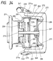
- Fig. 34 shows a fourteenth embodiment of the spinning reel for fishing according to the present invention, wherein retaining members for moving the restrainer, in place of the retaining portion 53 in the twelfth embodiment are provided on the spool.
- reference numeral 269 denotes a rotor rotatably fitted to the forward end of a reel body; and 271, a spool provided concentrically with the rotor 269 via a spool shaft 273.
- a fishing line is wound on the spool 271 as the rotor 273 is rotated by turning the manually operated handle.
- reference numeral 275 denotes a restrainer formed into a profile substantially similar to that of the restrainer 251. This restrainer 275 is also placed between the skirt portion 271a of the spool 271 and the cylindrical portion 277 of the rotor 269, and its rear end is extended up to the base of the bail support arms 237.
- the inner periphery of the skirt portion 271a of the spool 271 is provided with guide grooves 281 extending along the spool shaft 273, and mating portions 79 projected from the leading-end outer periphery of the restrainer 275 and arranged at the angular interval of 180° movably engage with the respective guide grooves 281.
- retaining portions 83 for retaining the respective mating portions 279 to move the restrainer 275 forward when the spool 271 is moved forward by turning the manually operated handle are inwardly projected from the forward end of the skirt portion 271a.
- Annular spring holding portions 285 and 287 centering around the spool shaft 273 are, as in the twelfth embodiment, formed on the forward-end inner face of the spool 271 and the forward-end surface of the restrainer 275 located opposite to the former, respectively. Moreover, the coil spring 259 which keeps urging the restrainer 251 backward is stretched between the coil spring holding portions 285 and 87.
- reference numeral 289 denotes an annular rubber ring fitted to the outer periphery of the cylindrical portion 277 of the rotor 269. At this time, the rubber ring 289 is depressingly in contact with the inner periphery of the restrainer 275 so as to prevent, like the retaining projections 265, the fishing line from entering the inside of the spool 271 or the inside of the restrainer 275 and being caught by the spool shaft 273.
- the spool 271 makes the reciprocating motion as the fishing line is wound thereon, and when the spool 71 is moved forward as shown in Fig. 34, the retaining portions 83 on the side of the spool 271 engage with the respective mating portions 279 of the restrainer 275 to move the restrainer 275 in the same direction. As the spool 271 is moved back then, the restrainer 275 is pushed back to the original position because the coil spring 259 urges the restrainer 275 toward the rotor 269.
- the restrainer 275 extends across the gap between the cylindrical portion 277 of the rotor 269 and the inner periphery of the skirt portion 271a of the spool 271 so as to prevent the fishing line from being caught by the spool shaft 273.
- the annular rubber ring 289 on the outer periphery of the rotor 269 also prevents the fishing line from being caught by the spool shaft 273 likewise.
- the fishing line is also prevented from entering the gap between the spool 271 and the rotor 269 and being caught by the spool shaft 273 without causing any trouble to the movements of the spool 271 and the rotor 269 in this embodiment like the twelfth embodiment shown in Fig. 28.
- the weight of the whole reel may increase even when the stroke of a spinning reel is lengthened and besides noise deriving from the backlash of the restrainer 275 can be obviated during the fishing operation.
- Figs. 35 and 36 show a fifteenth embodiment of the spinning reel for fishing according to the present invention, wherein reference numeral 291 denotes a rotor; and 293, a spool concentrically arranged with respect to the rotor 291.
- the spool 293 is supported with the spool shaft 247 and when the rotor 291 is rotated by turning the manually operated handle, the fishing line is wound onto the spool 293 making the reciprocating motion linking with the rotation of the rotor 291.
- the skirt portion of the spool 293 in this embodiment comprises four tongue-like skirt pieces 293a which are arcuate in cross section as shown in Fig. 36, these skirt pieces 293a forming the substantially cylindrical shape like the skirt portion 245a in the twelfth embodiment. Gaps 295 are provided for the respective adjacent pair of tongue-like skirt pieces, the gaps being arranged substantially at the angular interval of 90° .
- reference numeral 297 denotes a closed-end plastic cylindrical restrainer having a flange portion 299 for preventing the fishing line from being caught by the spool shaft 247.
- the flange portion 299 is formed at the rear end of the restrainer 97 and extended radially inwardly toward in the cylindrical portion 301 of the rotor 291.
- the restrainer 297 is formed with four arcuate recesses 303 into which the respective tongue-like skirt pieces 293a are fitted as shown in Fig. 36.
- the spool shaft 247 is passed through the center of the restrainer 297 so that the restrainer 297 is movably fitted thereto.
- the retaining portion 253 makes the restrainer 297 follow in the same direction.
- the restrainer 297 extends across the gap between the cylindrical portion 301 of the rotor 291 and the respective tongue-like skirt 293a of the spool 293 to prevent the fishing line from being caught by the spool shaft 247.
- the coil spring 259 is stretched via spring holding portions 305 and 307 on the forward-end inner face of the spool 293 and the forward-end surface of the restrainer 297 located opposite to the former.
- the coil spring 259 thus prevents the restrainer 297 from clattering.
- the spinning reel for fishing in this embodiment is thus constructed.
- the retaining portion 253 engages with the restrainer 297 and makes the restrainer 297 move in the same direction.
- the restrainer 297 is then pushed back to the original position because the coil spring 59 urges the restrainer 297 toward the rotor 291.
- the longitudinal movement of the restrainer 297 in this case is guided through the respective gaps 295 provided in between the tongue-like skirt pieces 293a.
- the restrainer 275 extends across the gap between the cylindrical portion 301 of the rotor 291 and the respective tongue-like skirt pieces 293a so as to prevent the fishing line from being caught by the spool shaft 247.
- the flange member 299 also prevents the fishing line from being caught by the spool shaft 273 likewise.
- Fig. 37 shows a sixteenth embodiment of the spinning reel for fishing according to the present invention, wherein the coil spring 259 in the embodiment of Fig. 28 is omitted and, in place of the retaining projections 265 provided on the rotor 233, retaining projections 309 projected toward the cylindrical portion 249' of a rotor 233' are provided at the rear end of a restrainer 251'' so as to prevent the entry of the fishing line toward the spool shaft 247.
- like reference characters are given to like component parts and the description thereof will be omitted.
- this embodiment refers to the omission of the coil spring for positively preventing the backlash or clattering of the restrainer 251''
- the backlash of the restrainer 251'' can be obviated to a certain extent by forming an oil film on the surface of the spool shaft 247 passed through the restrainer 251''.
- the present invention ensures that the fishing line is prevented from entering the inside of the spool without interference with the movements of the spool and the rotor in contrast with the prior art. Even when the stroke of the spinning reel is lengthened, moreover, there is little fear for the whole reel to become heavier.
Landscapes
- Life Sciences & Earth Sciences (AREA)
- Environmental Sciences (AREA)
- Animal Husbandry (AREA)
- Biodiversity & Conservation Biology (AREA)
Claims (21)
- Eine Angelwinde, bestehend aus einem rotierenden Teil (33), das drehbar auf einem Windenkörper (35) montiert ist, und einer Spule (45), die durch einen Spulenschaft (47) auf dem Windenkörper (35) gehalten ist, so daß die Spule sich axial zum Spulenschaft (47) hin- und herbewegbar ist und daß eine Angelschnur auf die Spule (45) aufgewickelt wird, wenn der rotierende Teil (33) durch einen handbetriebenen Griff (49) gedreht wird, weiter bestehend aus einer Angelschnureintrittsverhinderungseinrichtung (53), um zu verhindern, daß die Angelschnur sich um den Spulenschaft (47) wickelt,
gekennzeichnet dadurch,die Angelschnureintrittsverhinderungseinrichtung (53) ist beweglich auf einen zylindrischen Abschnitt (51) des rotierenden Teiles (33) aufgesetzt, so daß sie bezüglich des Spulenschafts (47) in axialer Richtung beweglich ist, wobei der zylindrische Abschnitt (51) derart angepaßt ist, daß er in der Spule (45) angeordnet ist; und weiterhin umfassendNachführmittel (67, 55a; 69, 55a), um die Angelschnureintrittsverhinderungseinrichtung (53) vorwärts zu bewegen, wenn die Spule (45) vorwärts bewegt wird. - Eine Angelwinde nach Anspruch 1, dadurch gekennzeichnet, daß das Nachführmittel (61, 55a), ein Rückhaltestück (55a) beinhaltet, das entweder auf der Spule (45) oder auf dem Spulenschaft (47) vorgesehen ist, und mit der Angelschnureintrittsverhinderungseinrichtung in Eingriff bringbar ist, um die Angelschnureintrittsverhinderungseinrichtung (53) vorwärts zu bewegen.
- Eine Angelwinde nach Anspruch 1, dadurch gekennzeichnet, daß das Nachführmittel (61, 55a) ein Federelement (123) beinhaltet, das zwischen dem rotierenden Teil (73) und Angelschnureintrittsverhinderungseinrichtung (115) gehalten wird, um die Angelschnureintrittsverhinderungseinrichtung (115) vorwärts zu treiben.
- Eine Angelwinde, bestehend aus einem rotierenden Teil (33; 153), das drehbar auf einem Windenkörper (35) montiert ist, und einer Spule (45;125), die durch einen Spulenschaft (47; 127) auf dem Spulenkörper (35) gehalten ist, so daß die Spule (45;125) sich axial zum Spulenschaft (47; 127) hin- und herbewegen kann, und daß die Angelschnur auf die Spule (45; 125) aufgewickelt wird, wenn das rotierende Teil (33; 153) durch einen handbetriebenen Griff (49) gedreht wird,
gekennzeichnet dadurch,eine weiterhin vorgesehene Angelschnureintrittsverhinderungseinrichtung (33, 153), die auf einem zylindrischen Abschnitt (155) des rotierenden Teiles (33; 153) montiert ist, wobei der zylindrische Abschnitt derart angepaßt ist, daß er in der Spule (45; 125) angeordnet ist,die Angelschnureintrittsverhinderungseinrichtung (51, 57; 151) eine Verhinderungseinrichtungsbasis (51, 151a), die fest mit dem zylindrischen Abschnitt (155) des rotierenden Teiles (153) verbunden ist; ein bewegliches Verhinderungseinrichtungsteil (57; 151b), das auf der Verhinderungseinrichtungsbasis (51; 151a) vorgesehen und in axialer Richtung bezüglich der Verhinderungseinrichtungsbasis (51; 151a) beweglich ist; und Nachführmittel (71; 123), um das bewegliche Verhinderungseinrichtungsteil (57; 151b) vorwärts zu bewegen, wenn die Spule (45; 125) vorwärts bewegt wird, umfaßt. - Eine Angelwinde nach Anspruch 4, dadurch gekennzeichnet, daß das Nachführmittel ein Rückhaltestück (71) umfaßt, das entweder auf der Spule (45) oder dem Spulenschaft (47) vorgesehen ist und mit dem beweglichen Verhinderungseinrichtungsteil (57) in Eingriff bringbar ist, um Angelschnureintrittsverhinderungseinrichtung (51, 57) vorwärts zu bewegen.
- Eine Angelwinde nach Anspruch 4, dadurch gekennzeichnet, daß das Nachführmittel ein Federelement (123) umfaßt, das zwischen dem rotierenden Teil (153) und dem beweglichen Verhinderungseinrichtungsteil (151b) gehalten ist, um das Verhinderungseinrichtungsteil (151b) vorwärts zu treiben.
- Eine Angelwinde, bestehend aus einem rotierenden Teil (233), das drehbar auf einen Windenkörper (75) montiert ist, und einer Spule (245), die durch den Spulenschaft (247) auf dem Windenkörper gehalten ist, so daß die Spule (245) sich axial zum Spulenschaft (247) hin- und herbewegen kann und die Angelschnur darauf aufwickelt wird, wenn das rotierende Teil (233) durch einen handbetriebenen Griff (49) gedreht wird, weiterhin umfassend eine Angelschnureintrittsverhinderungseinrichtung (251), die verhindert, daß die Angelschnur auf den Spulenschaft (247) aufgewickelt wird,
gekennzeichnet dadurch,die Angelschnureintrittsverhinderungseinrichtung (251) ist beweglich entweder auf der Innenfläche der Spule (245) oder dem Spulenschaft (247) montiert ist, so daß sie bezüglich des Spulenschafts (47) in axialer Richtung beweglich ist; und weiterhin umfassendNachführmittel (253), so daß die Angelschnureintrittsverhinderungseinrichtung (251) sich vorwärts bewegt, wenn die Spule (245) vorwärts bewegt wird. - Eine Angelwinde nach Anspruch 7, dadurch gekennzeichnet, daß das Nachführmittel ein Rückhaltestück (253) umfaßt, das entweder auf der Spule (245) oder dem Spulenschaft (247) vorgesehen ist und mit der Angelschnureintrittsverhinderungseinrichtung (251) in Eingriff bringbar ist, um die Angelschnureintrittsverhinderungseinrichtung (251) vorwärts zu bewegen.
- Eine Angelwinde nach Anspruch 7, weiterhin umfassendein Federelement (259), das zwischen der Spule (245) und der Angelschnureintrittsverhinderungseinrichtung (251) gehalten wird, um die Angelschnureintrittsverhinderungseinrichtung (251) in axialer Richtung rückwärts zu treiben.
- Eine Angelwinde bestehend aus:einem rotierenden Teil (233), das drehbar auf einem Windenkörper (235) gehalten ist;einer Spule (245), die durch einen Spulenschaft (247a) auf dem Windenkörper (235) gehalten ist, so daß eine Angelschnur auf die Spule (245) aufgewickelt werden kann, während sie in Verbindung mit der Drehung des rotierenden Teiles (233) eine Hin- und Herbewegung in axialer Richtung des Spulenschafts (247) ausführt; undeiner Angelschnureintrittsverhinderungseinrichtung (251), die verhindert, daß die Angelschnur zwischen die Spule (245) und das rotierende Teil (233) eindringt,
gekennzeichnet dadurch,die Verhinderungseinrichtung (251) ist entlang einer axialen Lücke erstreckbar, die zwischen der Spule (245) und dem rotierenden Teil (233) entsteht, wenn die Spule (245) sich relativ zum rotierenden Teil (233) in Richtung der Achse des Spulenschafts (247) hin- und herbewegt. - Eine Angelwinde nach Anspruch 10, dadurch gekennzeichnet, daß die Verhinderungseinrichtung (251) auf wenigstens eines der Elemente, auf die Spule (245) oder auf das rotierende Teil (233), beweglich aufgesetzt ist.
- Eine Angelwinde nach Anspruch 10, dadurch gekennzeichnet, daß die Verhinderungseinrichtung (251) beweglich auf den Spulenschaft (247a) aufgesetzt ist.
- Eine Angelwinde nach Anspruch 10, dadurch gekennzeichnet, daß die Verhinderungseinrichtung (151) eine Verhinderungseinrichtunsbasis (151a), die ortsfest an dem rotierenden Teil (153) befestigt ist, und ein bewegliches Verhinderungseinrichtungsteil (151b), das auf der Verhinderungseinrichtungsbasis (151a) gehalten wird und in Richtung der Achse bewegbar ist, umfaßt.
- Eine Angelwinde nach Anspruch 10, weiterhin umfassend:ein Nachführmittel (123), um die Verhinderungseinrichtung (151) vorwärts zu bewegen, wenn die Spule (125) vorwärts bewegt wird.
- Eine Angelwinde nach Anspruch 14, dadurch gekennzeichnet, daß das Nachführmittel ein Rückhalteteil (85) umfaßt, das entweder auf der Spule (245) oder auf dem Spulenschaft (247) ausgebildet ist und das mit der Verhinderungseinrichtung (251) in Eingriff bringbar ist, wenn die Spule (245) vorwärts bewegt wird.
- Eine Angelwinde nach Anspruch 15, weiterhin umfassend:ein Federelement (259), das zwischen der Spule (245) und der Verhinderungseinrichtung (251) zwischengeschaltet ist, um die Verhinderungseinrichtung (251) rückwärts zu treiben.
- Eine Angelwinde nach Anspruch 14, dadurch gekennzeichnet, daß das Nachführmittel ein Federelement (123) umfaßt, das zwischen dem rotierenden Teil (153) und der Verhinderungseinrichtung (151; 251) zwischengeschaltet ist, um die Verhinderungseinrichtung (151; 251) vorwärts zu treiben.
- Eine Angelwinde nach Anspruch 10, die weiter umfassend:ein Federelement (259), das zwischen der Spule (245) und der Verhinderungseinrichtung (251) zwischengeschaltet ist, um die Verhinderungseinrichtung (251) rückwärts zu treiben.
- Eine Angelwinde, umfassend:ein rotierendes Teil (99), das drehbar auf einem Windenkörper gehalten wird, wobei das besagte rotierende Teil ein Paar Stützarme (37) besitzt;eine Spule (97), die durch einen Spulenschaft (47) auf dem Spulenkörper gehalten ist, so daß eine Angelschnur auf die Spule aufgewickelt werden kann, während diese eine Hin- und Herbewegung in axialer Richtung des Spulenschafts (47) ausführt, die mit der Drehung des rotierenden Teiles im Zusammenhang steht; undeiner Angelschnureintrittsverhinderungseinrichtung (103), die auf dem rotierenden Teil (99) gehalten wird, um zu verhindern, daß die Angelschnur in eine radiale Lükke zwischen der äußeren Wandung der Spule (97) und den einzelnen Stützarmen (37) eindringt, wobei die Verhinderungseinrichtung (103) elastische Vorsprünge (113) hat, die sich radial über die äußere Wandung der Spule (97) erstreckt,
gekennzeichnet dadurch,daß die elastischen Vorsprünge (113) in Kontakt mit den radial inneren Flächen (37a) der jeweiligen Stützarme (37) gehalten werden. - Eine Angelwinde nach Anspruch 19, dadurch gekennzeichnet, daß die Verhinderungseinrichtung (103) drehbar auf die äußere Wandung der Spule (97) aufgesetzt ist.
- Eine Angelwinde Anspruch 19, dadurch gekennzeichnet, daß die Verhinderungseinrichtung (103) bezüglich des rotierenden Teiles (99) verschieblich ist.
Applications Claiming Priority (9)
| Application Number | Priority Date | Filing Date | Title |
|---|---|---|---|
| JP338620/93 | 1993-12-28 | ||
| JP33862093 | 1993-12-28 | ||
| JP33862093 | 1993-12-28 | ||
| JP8335494A JP2959662B2 (ja) | 1993-12-28 | 1994-04-21 | 魚釣用スピニングリール |
| JP83354/94 | 1994-04-21 | ||
| JP8335494 | 1994-04-21 | ||
| JP86708/94 | 1994-04-25 | ||
| JP8670894 | 1994-04-25 | ||
| JP6086708A JP3036620B2 (ja) | 1994-04-25 | 1994-04-25 | 魚釣用スピニングリール |
Publications (2)
| Publication Number | Publication Date |
|---|---|
| EP0660998A1 EP0660998A1 (de) | 1995-07-05 |
| EP0660998B1 true EP0660998B1 (de) | 1999-11-24 |
Family
ID=27304199
Family Applications (1)
| Application Number | Title | Priority Date | Filing Date |
|---|---|---|---|
| EP94120714A Expired - Lifetime EP0660998B1 (de) | 1993-12-28 | 1994-12-27 | Angelwinde |
Country Status (6)
| Country | Link |
|---|---|
| US (1) | US5615843A (de) |
| EP (1) | EP0660998B1 (de) |
| KR (1) | KR100336275B1 (de) |
| CN (1) | CN1082788C (de) |
| DE (1) | DE69421791T2 (de) |
| GB (1) | GB2285379B (de) |
Families Citing this family (7)
| Publication number | Priority date | Publication date | Assignee | Title |
|---|---|---|---|---|
| US5740976A (en) * | 1994-09-21 | 1998-04-21 | Zebco Division Of Brunswick Corporation | One-piece fishing reel subassembly |
| USD428106S (en) * | 1996-06-06 | 2000-07-11 | Daiwa Seiko, Inc. | Spool for a fishing spinning reel |
| US9724737B2 (en) * | 2013-03-15 | 2017-08-08 | Thomas Engineering Solutions & Consulting, Llc | Multi-lance reel for internal cleaning and inspection of tubulars |
| JP6831194B2 (ja) * | 2016-09-01 | 2021-02-17 | 株式会社シマノ | ロータ駆動部防水構造およびスピニングリール |
| JP6835601B2 (ja) * | 2017-01-19 | 2021-02-24 | 株式会社シマノ | 魚釣用スピニングリール |
| JP6871141B2 (ja) * | 2017-12-12 | 2021-05-12 | グローブライド株式会社 | 魚釣用スピニングリール |
| JP7166095B2 (ja) * | 2018-07-19 | 2022-11-07 | シマノコンポネンツ マレーシア エスディーエヌ.ビーエッチディー. | スピニングリール |
Family Cites Families (8)
| Publication number | Priority date | Publication date | Assignee | Title |
|---|---|---|---|---|
| FR988893A (fr) * | 1944-01-27 | 1951-09-03 | Perfectionnement apporté dans l'établissement des moulinets pour la peche | |
| US4106718A (en) * | 1970-10-30 | 1978-08-15 | The Garcia Corporation | Spinning reel spool and adapter therefor |
| US4561604A (en) * | 1983-07-18 | 1985-12-31 | Shimano Industrial Company Limited | Spinning reel |
| JPH0415016Y2 (de) * | 1986-09-30 | 1992-04-03 | ||
| US4834311A (en) * | 1987-10-15 | 1989-05-30 | Daiwa Seiko, Inc. | Fishline slip-off prevention device for a spinning reel |
| JPH039656A (ja) * | 1989-06-06 | 1991-01-17 | Ricoh Co Ltd | イメージセンサ |
| US5356091A (en) * | 1990-05-09 | 1994-10-18 | Shimano Inc. | Spinning reel |
| JP2532864Y2 (ja) * | 1990-06-22 | 1997-04-16 | 株式会社シマノ | スピニングリール |
-
1994
- 1994-12-20 US US08/359,616 patent/US5615843A/en not_active Expired - Fee Related
- 1994-12-20 GB GB9425689A patent/GB2285379B/en not_active Expired - Fee Related
- 1994-12-27 CN CN94113322A patent/CN1082788C/zh not_active Expired - Fee Related
- 1994-12-27 DE DE69421791T patent/DE69421791T2/de not_active Expired - Fee Related
- 1994-12-27 EP EP94120714A patent/EP0660998B1/de not_active Expired - Lifetime
- 1994-12-27 KR KR1019940037230A patent/KR100336275B1/ko not_active IP Right Cessation
Also Published As
| Publication number | Publication date |
|---|---|
| DE69421791T2 (de) | 2000-04-20 |
| CN1082788C (zh) | 2002-04-17 |
| KR100336275B1 (ko) | 2002-09-19 |
| US5615843A (en) | 1997-04-01 |
| CN1108877A (zh) | 1995-09-27 |
| KR950016505A (ko) | 1995-07-20 |
| GB9425689D0 (en) | 1995-02-22 |
| EP0660998A1 (de) | 1995-07-05 |
| DE69421791D1 (de) | 1999-12-30 |
| GB2285379B (en) | 1998-07-08 |
| GB2285379A (en) | 1995-07-12 |
Similar Documents
| Publication | Publication Date | Title |
|---|---|---|
| EP0660998B1 (de) | Angelwinde | |
| US5494232A (en) | Reversal preventive device | |
| US4561604A (en) | Spinning reel | |
| EP0783833B1 (de) | Angelwinde | |
| US5984220A (en) | Spinning reel having a narrow reel body housing | |
| US4778124A (en) | Line retaining means for a spinning reel | |
| EP0707790B1 (de) | Rücklaufsperre für Angelrolle | |
| US4222534A (en) | Fishing reel | |
| GB2317802A (en) | Fishing line retaining device for spinning reels | |
| US5615841A (en) | Fishline entrance preventive device for a fishing reel | |
| US5746382A (en) | Fishing spinning reel with spool having tapered portion and guide | |
| EP0711500B1 (de) | Angelrolle | |
| US5318247A (en) | Line retaining mechanism of a spinning reel | |
| US5139213A (en) | Fishing reel with level winder | |
| US5415358A (en) | Fishing reel with reciprocating cam shaft mechanism | |
| US6056221A (en) | Fishing reel with trigger actuated bail assembly | |
| US6056222A (en) | Spinning reel anti-reverse device | |
| US4834311A (en) | Fishline slip-off prevention device for a spinning reel | |
| US10555512B2 (en) | Spinning reel | |
| US5356091A (en) | Spinning reel | |
| US6199783B1 (en) | Spinning reel for fishing having spool support structure | |
| JP2994151B2 (ja) | 逆転防止装置 | |
| JP2925923B2 (ja) | 魚釣用スピニングリール | |
| JPH09107852A (ja) | スピニングリール | |
| JPH0615928Y2 (ja) | 線材巻取機のトラバース装置 |
Legal Events
| Date | Code | Title | Description |
|---|---|---|---|
| PUAI | Public reference made under article 153(3) epc to a published international application that has entered the european phase |
Free format text: ORIGINAL CODE: 0009012 |
|
| AK | Designated contracting states |
Kind code of ref document: A1 Designated state(s): DE DK FR IT SE |
|
| 17P | Request for examination filed |
Effective date: 19951006 |
|
| 17Q | First examination report despatched |
Effective date: 19971013 |
|
| GRAG | Despatch of communication of intention to grant |
Free format text: ORIGINAL CODE: EPIDOS AGRA |
|
| GRAG | Despatch of communication of intention to grant |
Free format text: ORIGINAL CODE: EPIDOS AGRA |
|
| GRAG | Despatch of communication of intention to grant |
Free format text: ORIGINAL CODE: EPIDOS AGRA |
|
| GRAH | Despatch of communication of intention to grant a patent |
Free format text: ORIGINAL CODE: EPIDOS IGRA |
|
| GRAH | Despatch of communication of intention to grant a patent |
Free format text: ORIGINAL CODE: EPIDOS IGRA |
|
| GRAA | (expected) grant |
Free format text: ORIGINAL CODE: 0009210 |
|
| AK | Designated contracting states |
Kind code of ref document: B1 Designated state(s): DE DK FR IT SE |
|
| PG25 | Lapsed in a contracting state [announced via postgrant information from national office to epo] |
Ref country code: SE Free format text: THE PATENT HAS BEEN ANNULLED BY A DECISION OF A NATIONAL AUTHORITY Effective date: 19991124 Ref country code: IT Free format text: LAPSE BECAUSE OF FAILURE TO SUBMIT A TRANSLATION OF THE DESCRIPTION OR TO PAY THE FEE WITHIN THE PRESCRIBED TIME-LIMIT;WARNING: LAPSES OF ITALIAN PATENTS WITH EFFECTIVE DATE BEFORE 2007 MAY HAVE OCCURRED AT ANY TIME BEFORE 2007. THE CORRECT EFFECTIVE DATE MAY BE DIFFERENT FROM THE ONE RECORDED. Effective date: 19991124 |
|
| PGFP | Annual fee paid to national office [announced via postgrant information from national office to epo] |
Ref country code: FR Payment date: 19991230 Year of fee payment: 6 Ref country code: DE Payment date: 19991230 Year of fee payment: 6 |
|
| REF | Corresponds to: |
Ref document number: 69421791 Country of ref document: DE Date of ref document: 19991230 |
|
| PG25 | Lapsed in a contracting state [announced via postgrant information from national office to epo] |
Ref country code: DK Free format text: LAPSE BECAUSE OF FAILURE TO SUBMIT A TRANSLATION OF THE DESCRIPTION OR TO PAY THE FEE WITHIN THE PRESCRIBED TIME-LIMIT Effective date: 20000224 |
|
| ET | Fr: translation filed | ||
| PLBE | No opposition filed within time limit |
Free format text: ORIGINAL CODE: 0009261 |
|
| STAA | Information on the status of an ep patent application or granted ep patent |
Free format text: STATUS: NO OPPOSITION FILED WITHIN TIME LIMIT |
|
| 26N | No opposition filed | ||
| PG25 | Lapsed in a contracting state [announced via postgrant information from national office to epo] |
Ref country code: DE Free format text: LAPSE BECAUSE OF NON-PAYMENT OF DUE FEES Effective date: 20011002 |
|
| PG25 | Lapsed in a contracting state [announced via postgrant information from national office to epo] |
Ref country code: FR Free format text: LAPSE BECAUSE OF NON-PAYMENT OF DUE FEES Effective date: 20020228 |
|
| PG25 | Lapsed in a contracting state [announced via postgrant information from national office to epo] |
Ref country code: FR Free format text: LAPSE BECAUSE OF NON-PAYMENT OF DUE FEES Effective date: 20001231 |