EP0660941B1 - Modulares mikroskopsystem - Google Patents
Modulares mikroskopsystem Download PDFInfo
- Publication number
- EP0660941B1 EP0660941B1 EP93918996A EP93918996A EP0660941B1 EP 0660941 B1 EP0660941 B1 EP 0660941B1 EP 93918996 A EP93918996 A EP 93918996A EP 93918996 A EP93918996 A EP 93918996A EP 0660941 B1 EP0660941 B1 EP 0660941B1
- Authority
- EP
- European Patent Office
- Prior art keywords
- microscope system
- modular microscope
- precision
- base body
- carrier
- Prior art date
- Legal status (The legal status is an assumption and is not a legal conclusion. Google has not performed a legal analysis and makes no representation as to the accuracy of the status listed.)
- Expired - Lifetime
Links
- 239000000969 carrier Substances 0.000 claims abstract description 9
- 230000003287 optical effect Effects 0.000 claims description 19
- 238000003780 insertion Methods 0.000 claims description 15
- 230000037431 insertion Effects 0.000 claims description 15
- 238000010276 construction Methods 0.000 claims description 9
- 239000002131 composite material Substances 0.000 claims description 2
- 210000000056 organ Anatomy 0.000 claims 2
- 239000007787 solid Substances 0.000 claims 1
- 238000004519 manufacturing process Methods 0.000 description 9
- 239000000919 ceramic Substances 0.000 description 3
- 239000000463 material Substances 0.000 description 3
- 238000013461 design Methods 0.000 description 2
- 238000006073 displacement reaction Methods 0.000 description 2
- 238000005516 engineering process Methods 0.000 description 2
- 238000005286 illumination Methods 0.000 description 2
- 229910052751 metal Inorganic materials 0.000 description 2
- 239000002184 metal Substances 0.000 description 2
- 238000000034 method Methods 0.000 description 2
- 230000010287 polarization Effects 0.000 description 2
- 238000013519 translation Methods 0.000 description 2
- 241001136792 Alle Species 0.000 description 1
- 229910001369 Brass Inorganic materials 0.000 description 1
- 241000397426 Centroberyx lineatus Species 0.000 description 1
- 241000272165 Charadriidae Species 0.000 description 1
- 241001290076 Papilio machaon Species 0.000 description 1
- 229910052782 aluminium Inorganic materials 0.000 description 1
- XAGFODPZIPBFFR-UHFFFAOYSA-N aluminium Chemical compound [Al] XAGFODPZIPBFFR-UHFFFAOYSA-N 0.000 description 1
- 238000004873 anchoring Methods 0.000 description 1
- 230000000712 assembly Effects 0.000 description 1
- 238000000429 assembly Methods 0.000 description 1
- 230000033228 biological regulation Effects 0.000 description 1
- 239000010951 brass Substances 0.000 description 1
- 229910010293 ceramic material Inorganic materials 0.000 description 1
- 238000006243 chemical reaction Methods 0.000 description 1
- 230000005484 gravity Effects 0.000 description 1
- 230000007257 malfunction Effects 0.000 description 1
- 238000000465 moulding Methods 0.000 description 1
- 238000009740 moulding (composite fabrication) Methods 0.000 description 1
- TWNQGVIAIRXVLR-UHFFFAOYSA-N oxo(oxoalumanyloxy)alumane Chemical compound O=[Al]O[Al]=O TWNQGVIAIRXVLR-UHFFFAOYSA-N 0.000 description 1
- 238000012545 processing Methods 0.000 description 1
- 239000000725 suspension Substances 0.000 description 1
- 238000012549 training Methods 0.000 description 1
Images

Classifications
-
- G—PHYSICS
- G02—OPTICS
- G02B—OPTICAL ELEMENTS, SYSTEMS OR APPARATUS
- G02B21/00—Microscopes
- G02B21/24—Base structure
-
- G—PHYSICS
- G02—OPTICS
- G02B—OPTICAL ELEMENTS, SYSTEMS OR APPARATUS
- G02B21/00—Microscopes
Definitions
- the invention relates to a modular microscope system with a composite Microscope base body, a tripod base, a tripod upper part and has an intermediate module with attachable binocular housing, wherein the base body is formed in a multi-part frame construction.
- chassis for optical Devices which as a 3-dimensional torsion-resistant hollow structure, which can be composed of several parts is, with extruded aluminum oxide being given as the material.
- the individual housing parts "hinge”, ie sintered together are or be releasably connected to each other, for. B. by Screw connections with tie rods.
- GB 1 164 241 A is a microscope with interchangeable ones Supplementary devices are known, with one component on the flat surface a microscope stand can be put on.
- this component is made using a Bayonet lock, located at one end of the elongated Component is flanged on the upper part of the tripod.
- the simple ones Support this module part. With such point conditions is only one Distance setting between the module and the tripod back. A spatially exact adjustment positioning is proposed with this constructive However, training is not possible
- a microscope system to provide the type mentioned at the beginning, taking into account ergonomic Aspects and using modern manufacturing technology a modular microscope system is specified in which a system-integrated upgrade and disassembly of the individual system components is possible, the viewing height being constant for the observers remains.
- the object is achieved by the features specified in the characterizing part of claim 1.
- the precision stop surfaces can in particular as a small-sized flat plant or. Support surfaces are formed, which with regard to their arrangement in the plane or in the space of the housing with the flat or spatial The dimensions of the beam to be fixed in the correct position correspond. It is also possible that the precision stop surfaces as non-flat contact or contact surfaces or as point contact or point contact surfaces are formed.
- a particularly advantageous one Embodiment is for the exact positioning of a carrier at least one one-piece combination stop surface system is provided, which has at least two precision stop surfaces, the themselves in a defined spatial assignment - preferably perpendicular to each other aligned levels - located.
- the precision stop surfaces mentioned can, for example, on cylindrical or frustoconical Housing protuberances from the inner ceiling wall of a Hang part of the main body stalactite-like, be arranged.
- the precision stop surfaces on cylindrical or frustoconical housing protuberances are arranged by protrude from the inner bottom wall of the base part like a stalagmite.
- the housing protuberances bearing the abutment surfaces along their longitudinal dimensions partly from the side walls of the body parts be recorded or merge with them spatially. It is additional possible that in the interior of the body parts plan and / or angled wall-shaped interior dividers are provided, which - if necessary - are provided with precision contact surfaces. You can the contact surfaces should be designed in such a way that they are only on one raised sub-area of the housing interior divider.
- the device according to the invention can be made so that some the protuberances or housing interior dividers which have the bearing surfaces have holes along their longitudinal extensions which with corresponding recesses, for example with holes, half-holes, Elongated holes, gaps and notches correspond in or on the beams.
- the carriers can be essentially 2-dimensional, for example as Platform, floor or slide, for attaching or inserting into or into one of the Subsystems of the microscope body are formed.
- the carrier as 3-dimensional housing parts, for example as a tube, cuboid, cube, prism, parallelepiped or as an angled one Chassis part, for attaching or inserting or pushing in or in at least one of the subsystems of the microscope body is formed are.
- At least one holding member is provided, which the carrier at least partially encompasses form-fitting, whereby for exact positioning this holding member also corresponding precision stop surfaces in or are provided on the base body parts.
- the carrier can also be used as Insert module can be formed in the along its optical axis several filters are arranged one behind the other, with associated filter slides can be brought into the operative position individually.
- the carrier can also be designed as an angled mounting part for the microscope stage be, the holder or guide in the vertical region of the tripod upper part Precision stop and guide surfaces for a backlash-free Vertical adjustment (z direction).
- the carrier in addition to optical components such as mirrors, Lenses and screens, additionally a final assembled revolver device has, in turn, pre-adjusted and final assembled components same type, but different physical-optical function, for example fluorescent divider cubes.
- the carrier can also be designed as a plug-in module by along its optical axis several diaphragms, for example fixed or variable fixed diaphragms or shape-variable diaphragms are arranged, which are assigned by means of Control means can be brought into the active position and - if necessary - variable in size can be adjusted.
- a tube lens having intermediate module which on the cantilevered horizontal part the upper part of the tripod using appropriate precision stop surfaces is attachable, is provided and that this against another Intermediate module, which in addition to a tube lens also a switchable and pre-adjusted Bertrand lens, is interchangeable such that the viewing height of the entire microscope system remains unchanged.
- a Another intermediate module is characterized in that it is additional a discontinuous magnification changer or a zoom system or has a polarization arrangement.
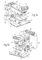
- FIGS. A modular microscope system is shown in FIGS. which contains a microscope body, which consists of a stand base (1), a Tripod top (2) and an intermediate module (3) with attachable or attachable Binocular housing (4).
- the tripod foot (1) goes in his part facing towards the observer in an ergonomic position on both sides flat palm rest (5) over.
- the upper stand part (2) has a vertical part on, on or in the side areas of manual operating means (6) are provided for the control of movement or regulation processes.
- a precision guide for a table bracket (8) provided with the Microscope stage (9) is detachably connected.
- a mirror housing (10) is adapted, on the one hand lamp housing (11, 12) and on the other hand another Housing module is assigned, which u. a. the electrical or the electronic supply and control devices for the overall system contains, cf. Figure 1b.
- the individual microscope base modules like tripod base (1), tripod upper part (2) and intermediate module (3), in one-piece construction, for example made of aluminum or brass, created in one manufacturing process, being in their respective Inside areas already cross walls or cross ribs or posts or angles or pegs made together with the actual housing module will. They are generally referred to in the present application referred to inward "housing protrusions”. It is from Meaning that the positioning and gauge blocks of these protuberances do not yet have to be available with the last required precision.
- the longitudinal extension of the frustoconical Align protuberances preferably in the direction of gravity, it is irrelevant whether they are on the inner upper ceiling wall of a horizontal housing part are formed stalactite-like or whether they're on the inner base surface of a horizontal body part in the manner of stalagmite-like columns or posts or pegs are positioned.
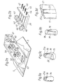
- Figure 4a on the inner Vertical walls of horizontal basic body parts formings (23) to be provided along as a cylindrical or frustoconical body its long side partially merge with the vertical inner wall and which taper downwards - i.e. towards the stand base (1).
- the Carrier (24) shown there with corresponding through holes (25b), and moreover in or on its end facing the tripod (2) Provide appropriate flange surfaces on the side with the stop surfaces (22) correspond.
- the carrier (24) in FIG. 4b has individual components, for example a deflecting mirror (26), lenses (27-29) and - if necessary - further beam deflecting, beam influencing or beam cross section changing Components. It is for the present invention of particular importance that all provided on the carrier (24) Components are already pre-adjusted and assembled, so that the Carrier (24), as it were, as a "socket part" for each individually positioned optical component can be viewed.
- the carrier (24) is fixed by means of screws. Equivalent fasteners are also possible, however the screw connection has the advantage of a releasable connection - For example, for conversion purposes when changing from a microscopic Observation type in another - has.
- the arrow (30) is the direction of incidence of an illumination beam specified; the assembly of the carrier (24) itself a reflected light module. It is in an optical connection with a fluorescence divider revolver (31), that with four fluorescence divider cubes (32-35) is populated with the fluorescence divider cube (34) in the version shown is currently in the active position and the at (30) incident light path in the direction of arrow (36) vertically deflected below towards the nosepiece not shown, that, as can be seen from FIG. 4a, is directed towards the observer Part of the horizontal area of the tripod upper part (2) as a plug-in module can be introduced, which is indicated by the arrow (37a) shown should be illustrated schematically.
- a filter module (39), as shown in Figure 2b will.
- This module (39) consists, for example, of 4 foldable ones Filters (40-43) using actuators that can be operated from the outside (44-47) one after the other optionally in the beam path, its optical Axis in the area of the module (39) or the support (24) with the reference number (48) is marked, can be brought. Because the positioning of filters in the optical illumination beam path are relatively non-critical is for the module (39) on a high-precision sliding guide to be dispensed with.
- the second insertion opening (49) in the horizontal part of the upper part of the tripod (2) serves to introduce an aperture module, not shown, compare in FIG. 4b and in FIG. 4c the one indicated by the arrow (50) Direction of insertion.
- the aperture module (51) by means of a dovetail guide (52) in the operative position hazards. It is of great importance that the swallowtail is integrally connected to the carrier (24). So that means that the precision guide is not in the frame part of the insertion opening (49) itself, but arranged on the precisely adjustable support (24) is.
- an intermediate module (3) ( Figure 5) are placed. He has a tube lens (53) and is in its lower area as well as in its upper area Binocular housing (4) facing area with corresponding, precisely created Stop and mounting surfaces provided.
- Other intermediate modules which, for example, have a Bertrand lens in addition to a tube lens or include a magnification changer or as a polarization module are conceived - at the choice of the observer - are also adaptable, whereby the viewing height does not change for the observer.
- a tubular support (56) in which lenses (57,58) as well a light field diaphragm (59) and an aperture diaphragm (60) already as prefabricated and pre-adjusted unit are installed.
- the tubular support (56) serves as a version and represents a module which can be used by means of the Housing protrusions with their precision stop faces positioned precisely in the optical axis (61) of the lighting tract can be.
- the illuminating beam hits after leaving the Illuminated field diaphragm (59) on a deflecting mirror (62), which is mounted on 2 inclined walls, which in turn have precision stop faces, positioned very precisely is.
- the carrier shown in Figures 4b and 4c (24) is essentially 2-dimensional (flat), the carrier (56) 3-dimensional as a cylindrical tube.
- the carrier at least partially form-fitting encompasses and also has precision stop surfaces that with existing precision stop surfaces in the housing modules correspond. More details regarding this tubular support bracket are in a patent application called: "Microscope stand base" executed, which is submitted at the same time.
Landscapes
- Physics & Mathematics (AREA)
- Chemical & Material Sciences (AREA)
- Analytical Chemistry (AREA)
- General Physics & Mathematics (AREA)
- Optics & Photonics (AREA)
- Microscoopes, Condenser (AREA)
- Undergarments, Swaddling Clothes, Handkerchiefs Or Underwear Materials (AREA)
- Packaging Frangible Articles (AREA)
Description
- Figur 1a:
- eine perspektivische Ansicht eines erfindungsgemäßen modularen Mikroskopsystems;
- Figur 1b:
- eine perspektivische Darstellung des in Figur la dargestellten Systems aus einer anderen Sicht mit zusätzlichem Gehäuse-Modul;
- Figur 2a:
- einen Stativfuß in perspektivischer, teilweise aufgeschnittener Darstellung;
- Figur 2b:
- einen einschiebbaren Filter-Modul in perspektivischer Darstellung;
- Figuren 3a - 3c:
- konische Gehäuse-Ausstülpungen mit Präzisions-Anschlagflächen;
- Figur 3d:
- einen wandförmigen Gehäuse-Innenraum-Aufteiler mit Präzisions-Anschlagfläche;
- Figur 4a:
- ein Stativoberteil in perspektivischer Darstellung;
- Figur 4b:
- einen erfindungsgemäßen 2-dimensionalen Träger mit vorjustierten Bauteilen;
- Figur 4c:
- den in Figur 4b dargestellten Träger mit zusätzlicher Schwalbenschwanz-Führung;
- Figur 5:
- einen Zwischen-Modul.
- 1:
- Stativfuß
- 2:
- Stativoberteil
- 3:
- Zwischen-Modul
- 4:
- Binokular-Gehäuse
- 5:
- Handauflage
- 6:
- manuelle Bedienmittel
- 7:
- Präzisions-Führung
- 8:
- Tischwinkel
- 9:
- Mikroskoptisch
- 10:
- Spiegelgehäuse
- 11,12:
- Lampengehäuse
- 13:
- Gehäuse-Modul
- 14,15,16:
- kegelstumpfförmige Ausstülpungen
- 17:
- wandförmiger Gehäuse-Innenraum-Aufteiler
- 18-22:
- Präzisions-Anschlagflächen
- 23:
- Anformung
- 24:
- Träger
- 25a:
- Bohrungen
- 25b:
- Ausnehmungen
- 26:
- Umlenkspiegel
- 27-29:
- Linsen
- 30,36:
- Pfeile
- 31:
- Fluoreszenzteiler-Revolver
- 32-35:
- Fluoreszenzteiler-Würfel
- 37a:
- Einschub-Richtung für Objektivrevolver
- 37b:
- Objektivrevolver
- 38:
- Einschub-Öffnung für Filter-Modul (39)
- 39:
- Filter-Modul
- 40-43:
- Filter
- 44-47:
- Stellglieder
- 48:
- optische Achse
- 49:
- Einschub-Öffnung für Blenden-Modul
- 50:
- Einschub-Richtung
- 51:
- Blenden-Modul
- 52:
- Schwalbenschwanz-Führung
- 53:
- Tubuslinse
- 54:
- Polarisator-Einschuböffnung
- 55:
- Analysator-Einschuböffnung
- 56:
- rohrförmiger Träger
- 57,58:
- Linsen
- 59:
- Leuchtfeldblende
- 60:
- Aperturblende
- 61:
- optische Achse
- 62:
- Umlenkspiegel
Claims (15)
- Modulares Mikroskopsystem mit einem zusammengesetzten Mikroskop-Grundkörper, der einen Stativfuß, ein Stativoberteil und einen Zwischen-Modul mit ansetzbarem Binokular-Gehäuse aufweist, wobei der Grundkörper in mehrteiliger Rahmenkonstruktion ausgebildet ist,
dadurch gekennzeichnet, daß der Grundkörper Präzisions-Anschlagflächen (18-22) aufweist, die so gestaltet sind, daß eine diskontinuierliche Kontaktierung von Trägern (24,56) für ihr räumlich justiergenaues Positionieren und Montieren erfolgt, wobei auf bzw. in den Trägern optische und/oder mechanische und/oder elektrische und/oder elektronische vorjustierte und endmontierte Einzelbauteile (26-29; 40-43; 62) bzw. zu funktionellen Einheiten zusammengefaßte vorjustierte und endmontierte Bauteil-Gruppen (31; 57-60) angeordnet sind. - Modulares Mikroskopsystem nach Anspruch 1,
dadurch gekennzeichnet, daß die Präzisions-Anschlagflächen (18-22) als kleindimensionierte plane Anlage- bzw. Aulageflächen ausge-bildet sind, die hinsichtlich ihrer Anordnung in der Ebene bzw. im Raum mit der flächigen bzw. räumlichen Dimensionierung des positionsgerecht zu fixierenden Trägers (24 bzw. 56) korrespondieren. - Modulares Mikroskopsystem nach mindestens einem der vorhergehenden Ansprüche,
dadurch gekennzeichnet, daß für die justiergenaue Positionierung eines Trägers (24; 56) mindestens ein einstückiges Kombinations-Anschlagflächensystem (15, 16) vorgesehen ist, das mindestens zwei Präzisions-Anschlagflächen (18-20) aufweist, die sich in definierter räumlicher Zuordnung - vorzugsweise in senkrecht zueinander ausgerichteten Ebenen - befinden. - Modulares Mikroskopsystem nach mindestens einem der vorhergehenden Ansprüche,
dadurch gekennzeichnet, daß die Präzisions-Anschlagflächen (18-20) auf zylindrischen oder kegelstumpfförmigen Gehäuse-Ausstülpungen (14-16), die von der inneren Deckenwandung eines Grundkörper-Teils stalaktitenartig herabhängen, angeordnet sind. - Modulares Mikroskopsystem nach mindestens einem der vorhergehenden Ansprüche,
dadurch gekennzeichnet, daß die Präzisions-Anschlagflächen (18-20) auf zylindrischen oder kegelstumpfförmigen Gehäuse-Ausstülpungen, die von der inneren Bodenwandung eines Grundkörper-Teils stalagmitenartig emporragen, angeordnet sind. - Modulares Mikroskopsystem nach mindestens einem der Ansprüche 4 und 5,
dadurch gekennzeichnet, daß die die Anschlagflächen (18-21) tragenden Gehäuse-Ausstülpungen (14-16, 23) entlang ihren Längsausdehnungen teilweise von den Seitenwandungen der Grundkörper-Teile aufgenommen werden. - Modulares Mikroskopsystem nach mindestens einem der vorhergehenden Ansprüche
dadurch gekennzeichnet, daß in den Innenräumen der Grundkörper-Teile plane und/oder gewinkelte wandförmige Gehäuse-Innenraum-Aufteiler (17) vorgesehen sind, die - gegebenenfalls - mit Präzisions-Auflageflächen (21) versehen sind. - Modulares Mikroskopsystem nach Anspruch 7,
dadurch gekennzeichnet, daß die Auflagefläche (21) nur auf einem erhaben ausgebildeten Teilbereich der Gehäuse-Innenraum-Aufteiler (17) angeordnet ist. - Modulares Mikroskopsystem nach mindestens einem der vorhergehenden Ansprüche,
dadurch gekennzeichnet, daß einige der die Präzisions-Anschlagflächen (18-22) aufweisenden Ausstülpungen (14-16, 23) bzw. Gehäuse-Innenraum-Aufteiler (17) entlang ihren Längserstreckungen Bohrungen (25a) aufweisen, die mit entsprechenden Ausnehmungen (25b) in bzw. an den Trägern (24) korrespondieren. - Modulares Mikroskopsystem nach mindestens einem der vorhergehenden Ansprüche,
dadurch gekennzeichnet, daß die Träger (24) im wesentlichen 2-dimensional - beispielsweise als Bühne, Boden oder Schieber - zum Anoder Einsetzen an bzw. in eines der Teilsysteme (1-3) des Mikroskop-Grundkörpers ausgebildet sind. - Modulares Mikroskopsystem nach mindestens einem der vorhergehenden Ansprüche 1 bis 9,
dadurch gekennzeichnet, daß die Träger als 3-dimensionale Gebäuseteile - beispielsweise als Rohr, Quader, Kubus, Prisma, Parallelepiped oder als gewinkeltes Chassis-Teil - zum An- oder Einsetzen oder Einschieben in mindestens eines der Teilsysteme (1-3) des Mikroskop-Grundkörpers ausgebildet sind. - Modulares Mikroskopsystem nach mindestens einem der Ansprüche 10 und 11,
dadurch gekennzeichnet, daß zusätzlich mindestens ein Halteorgan vorgesehen ist, das den Träger (24, 56) zumindest teilweise formschlüssig umgreift, und daß für die justiergenaue Positionierung dieses Halteorgans ebenfalls entsprechende Präzisions-Anschlagflächen (18-22) in bzw. an den Grundkörper-Teilen vorgesehen sind. - Modulares Mikroskopsystem nach mindestens einem der Ansprüche 9 bis 12,
dadurch gekennzeichnet, daß der Träger als abgewinkelte Halterung (8) für den Mikroskoptisch (9) ausgebildet ist, wobei die halterung im Vertikalbereich des Stativoberteils (2) Präzisions- Anschlags- und Führungsflächen für eine spielfreie Vertikalverstellung aufweist. - Modulares Mikroskopsystem nach mindestens einem der Ansprüche 9,11 und 12,
dadurch gekennzeichnet, daß der Träger neben optischen Bauelementen, wie Spiegeln (26), Linsen (27-29; 57, 58) und Blenden (58, 59), zusätzlich eine endmontierte Revolver-Einrichtung (31) aufweist, die ihrerseits vorjustierte und endmontierte Bauteile gleicher Art, aber unterschiedlicher physikalisch-optischer Funktion, beispielsweise Fluoreszenzteiler-Würfel (32-35), enthält. - Modulares Mikroskopsystem nach mindestens einem der vorhergehenden Ansprüche 9 bis 12,
dadurch gekennzeichnet, daß der Träger als Einschub-Modul (51) ausgebildet ist, in.dem entlang dessen optischer Achse mehrere Blenden - beispielsweise ortsfeste oder ortsvariable Festblenden oder formvariable Blenden - angeordnet sind, die mittels zugeordneter Steuerungsmittel in Wirkstellung bringbar und - gegebenenfalls - größenvariabel eingestellt werden können.
Applications Claiming Priority (3)
| Application Number | Priority Date | Filing Date | Title |
|---|---|---|---|
| DE4231470A DE4231470C2 (de) | 1992-09-19 | 1992-09-19 | Modulares Mikroskopsystem |
| DE4231470 | 1992-09-19 | ||
| PCT/DE1993/000860 WO1994007163A1 (de) | 1992-09-19 | 1993-09-15 | Modulares mikroskopsystem |
Publications (2)
| Publication Number | Publication Date |
|---|---|
| EP0660941A1 EP0660941A1 (de) | 1995-07-05 |
| EP0660941B1 true EP0660941B1 (de) | 1998-12-02 |
Family
ID=6468402
Family Applications (1)
| Application Number | Title | Priority Date | Filing Date |
|---|---|---|---|
| EP93918996A Expired - Lifetime EP0660941B1 (de) | 1992-09-19 | 1993-09-15 | Modulares mikroskopsystem |
Country Status (8)
| Country | Link |
|---|---|
| US (2) | US5585964A (de) |
| EP (1) | EP0660941B1 (de) |
| JP (1) | JP3067802B2 (de) |
| KR (1) | KR100281431B1 (de) |
| CN (1) | CN1047668C (de) |
| AT (1) | ATE174130T1 (de) |
| DE (4) | DE4245063B4 (de) |
| WO (1) | WO1994007163A1 (de) |
Families Citing this family (32)
| Publication number | Priority date | Publication date | Assignee | Title |
|---|---|---|---|---|
| CH690384A5 (de) | 1995-03-24 | 2000-08-15 | Zeiss Carl Fa | Computerunterstütztes Video-Mikroskop. |
| JP3735973B2 (ja) * | 1996-11-12 | 2006-01-18 | 株式会社ニコン | 顕微鏡 |
| DE59802165D1 (de) * | 1997-09-05 | 2001-12-20 | Leica Microsystems | Mikroskop, insbesondere fluoreszenzmikroskop, insbesondere stereo-fluoreszenzmikroskop |
| US6251101B1 (en) * | 1998-06-26 | 2001-06-26 | Visx, Incorporated | Surgical laser system microscope with separated ocular and objective lenses |
| US6678089B1 (en) * | 2000-04-13 | 2004-01-13 | Leica Microsystems Heidelberg Gmbh | Microscope |
| US6853481B1 (en) * | 1999-06-21 | 2005-02-08 | Olympus Optical Co., Ltd. | Microscope having an illumination optical system which is integrated with the microscope base which reduces heat conduction from the microscope base to the microscope frame |
| JP4624543B2 (ja) * | 2000-11-13 | 2011-02-02 | オリンパス株式会社 | 顕微鏡用照明装置 |
| DE10235388A1 (de) | 2002-08-02 | 2004-02-19 | Carl Zeiss Jena Gmbh | Optische Anordnung mit telezentrischem Strahlenbereich |
| DE10246277A1 (de) * | 2002-10-02 | 2004-04-15 | Leica Microsystems Wetzlar Gmbh | Mikroskop |
| DE20313678U1 (de) * | 2003-09-01 | 2004-02-19 | Leica Microsystems Wetzlar Gmbh | Mikroskop |
| JP2005215183A (ja) * | 2004-01-28 | 2005-08-11 | Olympus Corp | 顕微鏡および顕微鏡の静電気放電対策方法 |
| DE102004034847B4 (de) * | 2004-07-19 | 2016-01-28 | Leica Microsystems Cms Gmbh | Mikroskope mit manueller und externer Verstellmöglichkeit eines optischen Elements |
| DE102004034848B4 (de) * | 2004-07-19 | 2006-05-18 | Leica Microsystems Cms Gmbh | Inverses Mikroskop |
| DE112005002465B4 (de) | 2004-10-08 | 2017-07-06 | Nikon Corp. | Mikroskopsystem |
| EP1722421A3 (de) | 2005-05-13 | 2007-04-18 | Stmicroelectronics Sa | Integrierte massefreie Fotodiode |
| DE102005046241A1 (de) * | 2005-09-28 | 2007-04-12 | Leica Microsystems Cms Gmbh | Bildaufnahmeeinheit für mikroskopische Anwendungen |
| DE102006020737A1 (de) * | 2006-05-04 | 2007-11-08 | Westfälische Wilhelms-Universität Münster | Bewegungsdetektierendes modulares Mikroskopsystem |
| USD579959S1 (en) * | 2007-07-03 | 2008-11-04 | Leica Microsystems (Schweiz) Ag | Microscope |
| US20100302628A1 (en) * | 2007-08-07 | 2010-12-02 | Nikon Corporation | Microscope |
| USD601178S1 (en) * | 2008-04-11 | 2009-09-29 | Leica Microsystems (Schweiz) Ag | Microscope |
| JP5566625B2 (ja) * | 2009-04-15 | 2014-08-06 | 株式会社ハイロックス | デジタルマイクロスコープ用観察角度可変型スタンド |
| JP2012531631A (ja) | 2009-06-26 | 2012-12-10 | バイオ−ラッド ラボラトリーズ,インコーポレイティド | モジュラーマイクロスコープ構造 |
| US20110080638A1 (en) * | 2009-10-06 | 2011-04-07 | Dieter Feger | Microscope |
| US20110085234A1 (en) * | 2009-10-09 | 2011-04-14 | Dieter Feger | Microscope stand |
| USD657407S1 (en) * | 2009-12-15 | 2012-04-10 | Sanyo Electric Co., Ltd. | Microscope |
| US20120050853A1 (en) * | 2010-04-09 | 2012-03-01 | Andrew Ross Miller | Portable fluorescence microscope |
| JP5570963B2 (ja) | 2010-12-17 | 2014-08-13 | 株式会社ミツトヨ | 光学式測定装置 |
| JP5806537B2 (ja) * | 2011-07-20 | 2015-11-10 | オリンパス株式会社 | 顕微鏡セット |
| USD674424S1 (en) * | 2011-09-08 | 2013-01-15 | Leica Microsystems (Schweiz) Ag | Microscope |
| CN106370164A (zh) * | 2016-08-31 | 2017-02-01 | 蒋海洋 | 一种激光标线仪的机芯结构及激光标线仪 |
| US12474344B2 (en) | 2019-05-24 | 2025-11-18 | The Board Of Trustees Of The Leland Stanford Junior University | Spectral imaging platform for infectious disease diagnosis |
| CN111308876B (zh) * | 2019-12-12 | 2021-03-23 | 河北工程大学 | 一种减少干扰影响的反射式数字全息显微镜 |
Family Cites Families (11)
| Publication number | Priority date | Publication date | Assignee | Title |
|---|---|---|---|---|
| AT277610B (de) * | 1966-04-27 | 1969-12-29 | Leitz Ernst Gmbh | Mikroskop mit auswechselbaren Zusatz-Einrichtungen |
| DE1945364U (de) * | 1966-04-27 | 1966-09-01 | Leitz Ernst Gmbh | Mikroskop mit auswechselbaren ergaenzungseinrichtungen. |
| US4027841A (en) * | 1976-04-12 | 1977-06-07 | Varian Associates | Reproducible mounting of prealigned optical assemblies |
| DD146525B1 (de) * | 1979-10-17 | 1982-07-28 | Furchert Hans Juergen | Zweikoordinatenschrittmotor |
| DE3037556A1 (de) * | 1980-10-01 | 1982-05-27 | Le Materiel Biomedical, Paris | Lichtmikroskop |
| DE3230504C2 (de) * | 1981-08-26 | 1989-09-21 | Ernst Leitz Wetzlar Gmbh, 6330 Wetzlar | Durchlicht- und/oder Auflicht-Inversmikroskop |
| DE3211868A1 (de) * | 1982-03-31 | 1983-05-26 | Fa. Carl Zeiss, 7920 Heidenheim | Chassis fuer optische geraete |
| DE3523902A1 (de) * | 1984-08-01 | 1986-02-13 | Jenoptik Jena Gmbh, Ddr 6900 Jena | Mikroskopstativ |
| US5089909A (en) * | 1987-05-15 | 1992-02-18 | Storz Instrument Company | Documentation illumination module for a microscope system |
| JP2817301B2 (ja) * | 1989-12-28 | 1998-10-30 | 松下電器産業株式会社 | 光ヘッド |
| DE4231468A1 (de) * | 1992-09-19 | 1994-03-24 | Leica Mikroskopie & Syst | Mikroskopstativfuß |
-
1992
- 1992-09-19 DE DE4245063A patent/DE4245063B4/de not_active Expired - Fee Related
- 1992-09-19 DE DE4245060A patent/DE4245060B4/de not_active Expired - Fee Related
- 1992-09-19 DE DE4231470A patent/DE4231470C2/de not_active Expired - Lifetime
-
1993
- 1993-09-15 KR KR1019950701045A patent/KR100281431B1/ko not_active Expired - Fee Related
- 1993-09-15 DE DE59309193T patent/DE59309193D1/de not_active Expired - Lifetime
- 1993-09-15 JP JP6507679A patent/JP3067802B2/ja not_active Expired - Fee Related
- 1993-09-15 EP EP93918996A patent/EP0660941B1/de not_active Expired - Lifetime
- 1993-09-15 AT AT93918996T patent/ATE174130T1/de not_active IP Right Cessation
- 1993-09-15 WO PCT/DE1993/000860 patent/WO1994007163A1/de not_active Ceased
- 1993-09-15 US US08/397,122 patent/US5585964A/en not_active Ceased
- 1993-09-18 CN CN93117847A patent/CN1047668C/zh not_active Expired - Fee Related
-
1998
- 1998-12-16 US US09/212,295 patent/USRE37445E1/en not_active Expired - Fee Related
Also Published As
| Publication number | Publication date |
|---|---|
| KR950703749A (ko) | 1995-09-20 |
| KR100281431B1 (ko) | 2001-03-02 |
| ATE174130T1 (de) | 1998-12-15 |
| DE4245063B4 (de) | 2007-12-13 |
| WO1994007163A1 (de) | 1994-03-31 |
| DE59309193D1 (de) | 1999-01-14 |
| CN1084643A (zh) | 1994-03-30 |
| JP3067802B2 (ja) | 2000-07-24 |
| EP0660941A1 (de) | 1995-07-05 |
| DE4245060B4 (de) | 2007-12-06 |
| JPH08501163A (ja) | 1996-02-06 |
| DE4231470A1 (de) | 1994-03-24 |
| US5585964A (en) | 1996-12-17 |
| CN1047668C (zh) | 1999-12-22 |
| DE4231470C2 (de) | 2002-06-06 |
| USRE37445E1 (en) | 2001-11-13 |
Similar Documents
| Publication | Publication Date | Title |
|---|---|---|
| DE4231470C2 (de) | Modulares Mikroskopsystem | |
| EP1276586B1 (de) | Laser-mikro-dissektionsgerät | |
| DE3610692C2 (de) | ||
| EP0170857A1 (de) | Mikroskop mit einem binokularen Tubus | |
| EP2463702A1 (de) | Einrichtung und Verfahren zur justierten Anbringung eines Mikroskoptisches an einem Mikroskopstativ | |
| DE102004061901B4 (de) | Einrichtung zur Halterung von optischen Komponenten | |
| DE10352523A1 (de) | Invertierbares Lichtmikroskop | |
| DE4404286C2 (de) | Fluoreszenzeinrichtung für ein Invers-Mikroskop | |
| DE102014102248B4 (de) | Stereoskopisches optisches Beobachtungsgerät mit einem Hauptbeobachtersystem und einem Mitbeobachtersystem | |
| EP1018054B1 (de) | Mikroskopstativ für ein waferinspektionsmikroskop | |
| CH689405A5 (de) | Stereomikroskop mit einem Hauptobjektiv variabler Schnittweite | |
| WO2013045065A1 (de) | Laser-scanning-mikroskop | |
| DE102006024109A1 (de) | Mikroskop mit Wechseleinrichtung für optische Elemente | |
| EP3610314A1 (de) | Lichtblattmikroskop | |
| DE102019207873B4 (de) | Optischer Aufbau für ein Mikroskop und Mikroskop | |
| DE102006039896B4 (de) | Mikroskop | |
| DE29824597U1 (de) | Mikroskopanordnung | |
| DE2226137A1 (de) | Mikroskop mit variabler vergroesserung | |
| DE8807107U1 (de) | Projektionsmodul für Dia-Multivisionen oder Videowände | |
| EP1529234A1 (de) | Optische anordnung mit telezentrischem strahlenbereich | |
| DE102012007133A1 (de) | Kreuztisch für Durchlicht-Mikroskope | |
| DE102023113324B4 (de) | Mikroskop | |
| WO2000008509A1 (de) | Mikroskopanordnung | |
| DE102007053124B3 (de) | Kompaktes Linnik-Interferometer | |
| DE102004048296A1 (de) | Vorrichtung zum Umschalten der Betriebsarten eines Mikroskoptubus |
Legal Events
| Date | Code | Title | Description |
|---|---|---|---|
| PUAI | Public reference made under article 153(3) epc to a published international application that has entered the european phase |
Free format text: ORIGINAL CODE: 0009012 |
|
| 17P | Request for examination filed |
Effective date: 19950301 |
|
| AK | Designated contracting states |
Kind code of ref document: A1 Designated state(s): AT CH DE FR GB LI |
|
| 17Q | First examination report despatched |
Effective date: 19960607 |
|
| GRAG | Despatch of communication of intention to grant |
Free format text: ORIGINAL CODE: EPIDOS AGRA |
|
| GRAG | Despatch of communication of intention to grant |
Free format text: ORIGINAL CODE: EPIDOS AGRA |
|
| GRAH | Despatch of communication of intention to grant a patent |
Free format text: ORIGINAL CODE: EPIDOS IGRA |
|
| GRAH | Despatch of communication of intention to grant a patent |
Free format text: ORIGINAL CODE: EPIDOS IGRA |
|
| GRAA | (expected) grant |
Free format text: ORIGINAL CODE: 0009210 |
|
| RAP1 | Party data changed (applicant data changed or rights of an application transferred) |
Owner name: LEICA MICROSYSTEMS WETZLAR GMBH |
|
| AK | Designated contracting states |
Kind code of ref document: B1 Designated state(s): AT CH DE FR GB LI |
|
| REF | Corresponds to: |
Ref document number: 174130 Country of ref document: AT Date of ref document: 19981215 Kind code of ref document: T |
|
| REG | Reference to a national code |
Ref country code: CH Ref legal event code: EP |
|
| GBT | Gb: translation of ep patent filed (gb section 77(6)(a)/1977) |
Effective date: 19981202 |
|
| REF | Corresponds to: |
Ref document number: 59309193 Country of ref document: DE Date of ref document: 19990114 |
|
| ET | Fr: translation filed | ||
| PLBE | No opposition filed within time limit |
Free format text: ORIGINAL CODE: 0009261 |
|
| STAA | Information on the status of an ep patent application or granted ep patent |
Free format text: STATUS: NO OPPOSITION FILED WITHIN TIME LIMIT |
|
| 26N | No opposition filed | ||
| REG | Reference to a national code |
Ref country code: GB Ref legal event code: IF02 |
|
| PGFP | Annual fee paid to national office [announced via postgrant information from national office to epo] |
Ref country code: GB Payment date: 20090922 Year of fee payment: 17 Ref country code: CH Payment date: 20090923 Year of fee payment: 17 Ref country code: AT Payment date: 20090916 Year of fee payment: 17 |
|
| PGFP | Annual fee paid to national office [announced via postgrant information from national office to epo] |
Ref country code: DE Payment date: 20090922 Year of fee payment: 17 |
|
| REG | Reference to a national code |
Ref country code: CH Ref legal event code: PL |
|
| GBPC | Gb: european patent ceased through non-payment of renewal fee |
Effective date: 20100915 |
|
| REG | Reference to a national code |
Ref country code: FR Ref legal event code: ST Effective date: 20110531 |
|
| REG | Reference to a national code |
Ref country code: DE Ref legal event code: R119 Ref document number: 59309193 Country of ref document: DE Effective date: 20110401 |
|
| PG25 | Lapsed in a contracting state [announced via postgrant information from national office to epo] |
Ref country code: LI Free format text: LAPSE BECAUSE OF NON-PAYMENT OF DUE FEES Effective date: 20100930 Ref country code: CH Free format text: LAPSE BECAUSE OF NON-PAYMENT OF DUE FEES Effective date: 20100930 Ref country code: FR Free format text: LAPSE BECAUSE OF NON-PAYMENT OF DUE FEES Effective date: 20100930 Ref country code: DE Free format text: LAPSE BECAUSE OF NON-PAYMENT OF DUE FEES Effective date: 20110401 |
|
| PG25 | Lapsed in a contracting state [announced via postgrant information from national office to epo] |
Ref country code: GB Free format text: LAPSE BECAUSE OF NON-PAYMENT OF DUE FEES Effective date: 20100915 Ref country code: AT Free format text: LAPSE BECAUSE OF NON-PAYMENT OF DUE FEES Effective date: 20100915 |
|
| PGFP | Annual fee paid to national office [announced via postgrant information from national office to epo] |
Ref country code: FR Payment date: 20091001 Year of fee payment: 17 |