EP0657015B2 - Schornsteinfuss - Google Patents
Schornsteinfuss Download PDFInfo
- Publication number
- EP0657015B2 EP0657015B2 EP93918944A EP93918944A EP0657015B2 EP 0657015 B2 EP0657015 B2 EP 0657015B2 EP 93918944 A EP93918944 A EP 93918944A EP 93918944 A EP93918944 A EP 93918944A EP 0657015 B2 EP0657015 B2 EP 0657015B2
- Authority
- EP
- European Patent Office
- Prior art keywords
- container
- chimney
- chimney base
- aperture
- end section
- Prior art date
- Legal status (The legal status is an assumption and is not a legal conclusion. Google has not performed a legal analysis and makes no representation as to the accuracy of the status listed.)
- Expired - Lifetime
Links
- 239000007788 liquid Substances 0.000 claims abstract description 30
- 238000006386 neutralization reaction Methods 0.000 claims abstract description 5
- UGFAIRIUMAVXCW-UHFFFAOYSA-N Carbon monoxide Chemical compound [O+]#[C-] UGFAIRIUMAVXCW-UHFFFAOYSA-N 0.000 claims abstract 2
- 239000003546 flue gas Substances 0.000 claims abstract 2
- 238000004140 cleaning Methods 0.000 claims description 13
- 239000000523 sample Substances 0.000 claims description 3
- 238000005273 aeration Methods 0.000 claims 2
- 230000005494 condensation Effects 0.000 claims 1
- 238000009833 condensation Methods 0.000 claims 1
- 230000000284 resting effect Effects 0.000 claims 1
- 239000004575 stone Substances 0.000 description 15
- 239000003795 chemical substances by application Substances 0.000 description 7
- 230000003472 neutralizing effect Effects 0.000 description 7
- 238000009423 ventilation Methods 0.000 description 7
- 239000004743 Polypropylene Substances 0.000 description 2
- 238000005253 cladding Methods 0.000 description 2
- 239000003550 marker Substances 0.000 description 2
- -1 polypropylene Polymers 0.000 description 2
- 229920001155 polypropylene Polymers 0.000 description 2
- OYPRJOBELJOOCE-UHFFFAOYSA-N Calcium Chemical compound [Ca] OYPRJOBELJOOCE-UHFFFAOYSA-N 0.000 description 1
- 229910000831 Steel Inorganic materials 0.000 description 1
- 230000006978 adaptation Effects 0.000 description 1
- 239000011449 brick Substances 0.000 description 1
- 229910052791 calcium Inorganic materials 0.000 description 1
- 239000011575 calcium Substances 0.000 description 1
- 229910010293 ceramic material Inorganic materials 0.000 description 1
- 238000009792 diffusion process Methods 0.000 description 1
- 238000005516 engineering process Methods 0.000 description 1
- 239000008187 granular material Substances 0.000 description 1
- 230000002706 hydrostatic effect Effects 0.000 description 1
- 238000009413 insulation Methods 0.000 description 1
- 238000012423 maintenance Methods 0.000 description 1
- 239000000463 material Substances 0.000 description 1
- 230000035515 penetration Effects 0.000 description 1
- 238000007789 sealing Methods 0.000 description 1
- 239000010959 steel Substances 0.000 description 1
- 239000000126 substance Substances 0.000 description 1
Images


Classifications
-
- F—MECHANICAL ENGINEERING; LIGHTING; HEATING; WEAPONS; BLASTING
- F24—HEATING; RANGES; VENTILATING
- F24H—FLUID HEATERS, e.g. WATER OR AIR HEATERS, HAVING HEAT-GENERATING MEANS, e.g. HEAT PUMPS, IN GENERAL
- F24H8/00—Fluid heaters characterised by means for extracting latent heat from flue gases by means of condensation
- F24H8/006—Means for removing condensate from the heater
-
- F—MECHANICAL ENGINEERING; LIGHTING; HEATING; WEAPONS; BLASTING
- F23—COMBUSTION APPARATUS; COMBUSTION PROCESSES
- F23J—REMOVAL OR TREATMENT OF COMBUSTION PRODUCTS OR COMBUSTION RESIDUES; FLUES
- F23J2900/00—Special arrangements for conducting or purifying combustion fumes; Treatment of fumes or ashes
- F23J2900/13004—Water draining devices associated with flues
-
- Y—GENERAL TAGGING OF NEW TECHNOLOGICAL DEVELOPMENTS; GENERAL TAGGING OF CROSS-SECTIONAL TECHNOLOGIES SPANNING OVER SEVERAL SECTIONS OF THE IPC; TECHNICAL SUBJECTS COVERED BY FORMER USPC CROSS-REFERENCE ART COLLECTIONS [XRACs] AND DIGESTS
- Y02—TECHNOLOGIES OR APPLICATIONS FOR MITIGATION OR ADAPTATION AGAINST CLIMATE CHANGE
- Y02B—CLIMATE CHANGE MITIGATION TECHNOLOGIES RELATED TO BUILDINGS, e.g. HOUSING, HOUSE APPLIANCES OR RELATED END-USER APPLICATIONS
- Y02B30/00—Energy efficient heating, ventilation or air conditioning [HVAC]
Definitions
- the invention relates to a chimney foot with liquid drainage for an outer jacket and inner tube having chimney, in which for the inner pipe one on the lower end of the chimney Support provided with a passage for liquid and the lower end section of the chimney foot a side opening for inserting a container has in the interior.
- Chimneys especially chimneys, have a leading the exhaust gas of a furnace Inner tube on that arranged within an outer jacket is.
- the outer jacket is made of individual jacket stones. the inner tube from individual tube sections put together.
- the inner tube is at the foot of the Chimney supported and can due to thermal expansion occurring changes in length in the axial direction consequences.
- Through rain falling from above or condensate forming on the cold inner tube Liquid collects in the area of the base of the chimney on. To avoid moisture penetration of the Chimney base and an adjoining one Sooting the chimney must drain this liquid become.
- a chimney is known from US-A-2,277,436 which can be manufactured at low cost and for low price Home projects can be sold, however Advantages of one made of clinker or brick Chimney should have.
- This chimney owns an inner tube surrounded by thermal insulation or Exhaust pipe. that of several shots of enamelled Steel is composed.
- the lower end section the chimney forms a support.
- on one Plate is mounted on which the inner tube or exhaust pipe rests. In the center of the plate is one with a hole connected opening provided on the one line connected to a channel.
- the chimney does not have an outer sheath made of mantle stones, rather, US-A-2,277,436 aims to do so. such Replace chimneys with a cheaper product.
- a chimney foot is known from DE-A-37 11 313. in which the passage to the outer wall of the Chimney foot leads and the neutralization vessel in front of or next to the chimney foot on the basement floor stands.
- From DE-U-86 33 052 is a keystone designated one-piece support known that a trough on the top with a drain on the bottom having. This support can be above be attached to the floor and allowed underneath a condensate collector inside the chimney cross-section can be set up. The space below the support is accessible from the side.
- the object of the present invention is a To create the chimney base as a complete component can be delivered, transported and moved, and at which is a reliable, gas-tight discharge of the liquid guaranteed from the outlet opening into the container is.
- the entire chimney base can be moved as a finished part, because the chimney foot is composed of mantle stones that are common connected to the support to form a unit are.
- the connection is made by Tie rod.
- the screwed on the upper ends of the tie rods become.
- the crane eyelets can be exchanged for fasteners to the chimney base with a attached further chimney component tensile connect to.
- the lower end section of the chimney base in the usual for mantle stones Height of 323 mm.
- the outer jacket this lower end section has only three outer walls on. so that it is approximately U-shaped in cross section
- the entire interior of the lower end section thus stands available to hold the container.
- the support for lies on the lower end section the inner tube. There is no need for an additional base become.
- the container If the amount of liquid is particularly high, so can the container with a to a sewer leading line. Unless there is a floor drain is available in the basement, the Schomstein foot on a commercially available condensate pump receiving base can be placed.
- the base can be a conventional casing stone, in the Inside there is space for the condensate pump. The maintenance the condensate pump is removed from above of the container possible. In this way can also use a condensate pump without additional Space requirements can be accommodated.
- a cleaning opening is provided above the support in the inner tube and the outer jacket surrounding this, preferably second casing stone.
- the cleaning opening in the inner tube as well as in the outer jacket can with a usual Cleaning door arrangement can be closed.
- Ventilation of the space between the inner tube and outer casing of the chimney is possible if above the cleaning opening in the outer jacket.
- a ventilation opening is provided in the third casing stone.
- the ventilation opening is usually provided with a ventilation grille.
- a functional and elegant design of the Chimney foot is reached when the opening that Cleaning opening and possibly the ventilation opening one above the other in the same wall of the outer jacket arranged and their borders with a common Cladding are provided.
- Discharge of liquid from a support to the container is done in that the support preferably a passage in the center for liquid that has a line with is connected to the container.
- the interior of the lower end section and thus the free end of the line is in contact with the outside air Connection while in the inner pipe of the chimney. from which the passage originates, negative or positive pressure can rule. It is therefore important that the suction of external air at negative pressure or the escape of exhaust gas is avoided if there is overpressure in the inner tube.
- the hydrostatic is used for this Closure of the line.
- For example can be provided in the line a siphon or that The end of the line can be immersed in the liquid in the container.
- the container can be drawer-like in the interior the lower end section of the Schomstein foot be introduced when on the side walls of the interior one support each to hold one each side wall of the container preferably in the area its upper end arranged projection is provided.
- the protrusions can be seen from the side walls protruding ledges of the container, for example as ribs or cantilevers.
- the Outriggers can be in the form of U-shaped rails or the like be trained. When inserting the container in the lower end of the chimney base this is through the protrusions and supports laterally and precisely in its altitude, so that the connector at the end of the line in one on the Slide the opening on the back of the container can.
- the container is particularly light like a drawer into the interior of the lower end portion of the Chimney base insertable when the container is essentially is cuboid, at the top of the container a recess is provided for the inlet of the nozzle and this is above a horizontal one in the container Directed fixed with neutralizing agent Receptacle opens.
- the available interior in the chimney base is optimally used when the width and depth of the Condensate tank are only slightly less than the interior dimensions of the interior.
- Moving the receptacle in the container is prevented because the receptacle is horizontal Direction is fixed. This can be done, for example be done on the bottom of the container Stop is provided, and that the receptacle lies against the wall of the container.
- the receptacle is advantageously in the container near the back wall and the recess at the top Edge of the rear wall arranged.
- the neck for Condensate inlet can be attached to the chimney base and slightly inclined through the recess in the rear wall of the container protrude into it and over end of the open receptacle.
- the receptacle is advantageously cylindrical trained and has an openwork Floor on.
- the interior of the container is behind Loosen a lid accessible.
- the essentially freely inserted into the container and preferably on receptacle placed at the bottom of the container with used and / or dirty content can be easily removed to clean it and refill.
- the introduction of neutralizing agents is particularly convenient when this is in one adapted to the internal dimensions of the receptacle Bag is packed.
- the bag should be made of liquid permeable Material like waterproof filter paper or fleece exist.
- the receptacle If the receptacle is clogged, it can if necessary, condensate overflow without getting in the line backing up.
- receptacles are different Size can be used.
- one of the adjusted amount of neutralizing agent required Containers are used.
- Round receptacles have different ones Diameter on.
- a simple check of the contents of the container is possible if an opening is provided in the lid through which either a level indicator or a measuring probe can be inserted.
- a first overflow is advantageously on the front wall arranged.
- the overflow can be special be trained to save space. when he's in the area a vertical edge of the container is arranged and the vertical edge is drawn in below the overflow is. At the overflow can be a vertical down leading hose connector must be attached. The overflow is located below the top of the container, so that this can be operated without pressure and on sealing of the cover can be dispensed with.
- the arrangement of the overflow outside the receptacle and below the top of the container ensures that the greatest possible dwell time is used for neutralization, because even after leaving the entire contents of the receptacle the container in connection with the neutralizing agent, so that an intensive exchange of substances by diffusion can take place.
- the condensate pump can also be connected a slightly lower than the first overflow second overflow can be provided, preferably on the back wall in the area of another vertical Edge of the container, with the vertical edge below the second overflow has also moved in. In the delivery state, the second overflow is closed, so that no condensate can escape if no condensate pump is connected.
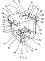
- a chimney base 10 with a Outer jacket 12 and an inner tube 14 shown.
- the chimney base 10 In the interior 16 of the lower end section 18 the chimney base 10 is a container 20 for receiving of liquid arranged.
- a wall of the Outer jacket 12 forming jacket stone 21 of the lower End section 18 is an opening 22 for introducing the Container 20 provided.
- the support 24 is in this Example executed in two parts and carries one made of ceramic Material existing base plate 26 on the the inner tube 14 is seated.
- a passage 28 is provided for liquid, which connected to the container 20 via a line 30 is.
- a siphon 32 is arranged in the line 30.
- Passage 28 and line 30 with siphon 32 are inside of the casing stone 21 arranged.
- Line 30 opens from the side opposite the opening 22 with one arranged substantially horizontally Neck 34 in the container 20 in the area of the upper In the end.
- the nozzle 34 runs with a slight slope towards its end.
- the container 20 is a neutralization vessel formed, being in a receptacle 44 a suitable neutralizing agent such as granules calcium-based or ion exchanger can be.
- a ventilation opening is located above the cleaning opening 46 48 in a third casing stone 49 in the outer casing 12 provided, protected by a grid 50 is.
- the first cladding stone 21 of the lower end section 18, the support 24, the second casing stone 47 with the Cleaning opening 46 and the third casing stone 49 with the ventilation opening 48 are interconnected by tie rods 52, 54 connected.
- tie rods 52, 54 connected to the drawing.
- Fig. 1 is one for transportation at the upper end of the tie rod 52 screwed crane eye 54 shown.
- a container 20 made of polypropylene is in perspective shown.
- the rectangular container 20 is 250 mm high, 200 mm wide and 245 mm deep.
- To the Side walls 62, 64 of the container 20 are 35 mm below the upper edge 65 than on the outside projections about 5 mm protruding ribs 36 and 38 arranged by the rear wall Go out 70 and end 35 mm in front of the front wall 72.
- the container 20 is like a drawer in the front open interior 16 of the chimney base 10 insertable, the projections 36, 38 on supports 40, 42 of the chimney base slide.
- the rear wall 74 of the container 20 is from the upper edge 65 starting from a 31 mm deep U-shaped recess 76 provided through which the slightly inclined neck 34 protrudes into the interior of the container 20.
- the Mouth 80 of the nozzle 34 is above a cylindrical Receiving container 44 for neutralizing agent arranged.
- the receptacle 44 has an openwork Bottom so that neutralized condensate in there can escape the interior of the container 20.
- On the inside of the bottom wall 84 of the container 20 are ribs 86, 88, 90, 92, 94 for supporting the receptacle 44 arranged.
- Rib 86 is diagonal on the bottom wall 84 of the container 20 arranged and outside that occupied by the smallest receptacle 44 Surface formed higher than the other ribs 88, 90, 92 and 94. In the higher section the rib 86 are depressions 96, 98, 100 for fixing the position of receptacles 44 with larger diameters arranged.
- a first overflow 104 with a vertically downward leading first hose connector 106 attached.
- the front right Edge 102 retracted so that one to a floor drain leading first line can be connected can.
- the rear left edge 108 of the container 20 is 58 mm below the top edge 65 a second overflow 110 with a vertical after attached second hose connector 112 attached.
- the second overflow 110 is the rear one left edge 108 retracted so that one to one Condensate pump leading second line connected can be.
- the second hose connector 112 is closed.
- the container 20 from FIG. 3 has a Lid 122 made of polypropylene shown in perspective.
- a front wall 72 of the container 20 covering front panel 124 formed.
- On the top of the lid 122 is one up to the front panel 124 extending recessed grip 126 with one in the Center of the cover 122 arranged parallel to the front panel 124 first handle 128 and one on the front panel 124 arranged second handle 129 is provided From the edge of the cover 122 there is an outside on the rear wall 74 and the side walls 62, 64 of the container 20 adjacent 35 mm wide angled at right angles Flap 130 along the side edges 132, 134 the front panel 124 is continued. At the lower edge 136 of the front panel 124 is near the right side edge 134 one of notch wells 138 on the back limited U-shaped section 140 provided after Section 140 can break out at this point the first line can be led out.
- the level indicator 144 is in the Shown longitudinal section, in Fig. 5 with a filled container and in Fig. 6 with the container partially filled, the Liquid level 150 represented by a wavy line is.
- the fill level indicator 144 has an angular shape Bracket 152, which is an opening in the lid 122 final cover plate 154 and one of their trailing edge going downwards at right angles Guide bar 152 for a float 158 has.
- the float 158 slides in between the guide bar 152 and the front wall 72 of the container 20 formed shaft-like space 160.
- the float 158 is approximately in longitudinal section E-shaped, with the vertical section on slides along the guide bar 152. Between the lower and middle legs of the E-shaped Floating body 158 is a hollow ball Float 162 arranged which the float 158 rises as soon as the liquid level 150 the has reached the appropriate height. The upper leg of the E-shaped float 158 forms the marker pointer 148 moving in the viewing window 146. In the lowest position of the float 158 is the Marking pointer 148 on the front wall 72 of the container 20 below the viewing window 146 on and is covered by the somewhat higher front panel 124, as long as the liquid level 150 is low.
- the entire level indicator 144 can from the Lid 122 of the container 20 are removed, so that through the opened opening 143 Measuring probe can be inserted, for example determine the pH of the liquid.
Landscapes
- Engineering & Computer Science (AREA)
- General Engineering & Computer Science (AREA)
- Chemical & Material Sciences (AREA)
- Thermal Sciences (AREA)
- Combustion & Propulsion (AREA)
- Mechanical Engineering (AREA)
- Physics & Mathematics (AREA)
- Details Of Rigid Or Semi-Rigid Containers (AREA)
- Devices For Executing Special Programs (AREA)
- Reciprocating, Oscillating Or Vibrating Motors (AREA)
- Fire-Extinguishing Compositions (AREA)
- Nozzles (AREA)
- Catching Or Destruction (AREA)
- Semiconductor Lasers (AREA)
- Filling Or Discharging Of Gas Storage Vessels (AREA)
Description
- Fig. 1
- einen erfindungsgemäßen Schornsteinfuß im Längsschnitt
- Fig. 2
- den Schornsteinfuß aus Fig. 1 in um 90° gedrehtem Längsschnitt.
- Fig. 3
- ein Behältnis in perspektivischer Darstellung,
- Fig. 4
- das Behältnis aus Fig. 3 in perspektivischer Darstellung mit einem Deckel.
- Fig 5
- einen Füllstandanzeiger des Behältnisses aus Fig. 3 im Längsschnitt bei gefülltem Behältnis und
- Fig. 6
- den Füllstandanzeiger aus Fig. 5 im Längsschnitt bei teilweise gefülltem Behältnis.
Claims (11)
- Schornsteinfuß (10) für einen Außenmantel (12) und Innenrohr (14) aufweisenden Schornstein,wobei der Schornsteinfuß mit einer Flüssigkeitsableitung versehen ist und einen Außenmantel aus drei Mantelsteinen (21,47,49) sowie eine auf dem Mantelstein (21) seines unteren End abschnitts (18) aufliegende Abstützung (24) für das Innenrohr (14) aufweist,wobei der untere End abschnitt (18) in seinem Innenraum (16) ein Behältnis (20) und eine seitliche Öffnung (22) zum Einbringen des Behältnisses in den Innenraum (16) aufweist,wobei die Mantelsteine (21, 47, 49) und die Abstützung (24) miteinander durch Zuganker zu einer Einheit verbunden sind,wobei die Abstützung (24) einen Durchlaß (28) für Flüssigkeit aufweist und eine hydrostatisch gegen den Durchtritt von Falschluft bzw. Abgas verschließbare Leitung (30) den Durchlaß (28) mit dem Behältnis (20) verbindet.
- Schornsteinfuß nach Anspruch 1,
dadurch gekennzeichnet,
daß der untere Endabschnitt (18) des Schornsteinfußes (10) einen eine Kondensatpumpe aufnehmenden Sockel aufweist. - Schornsteinfuß nach 1 oder 2,
dadurch gekennzeichnet,
daß oberhalb der Abstützung (24) im Innenrohr (14) und im Außenmantel (12) eine Reinigungsöffnung (46) vorgesehen ist. - Schornsteinfuß nach Anspruch 3,
dadurch gekennzeichnet,
daß oberhalb der Reinigungsöffnung (46) im Außenmantel (12) eine Lüftungsöffnung (48) vorgesehen ist. - Schornsteinfuß nach Anspruch 3 oder 4,
dadurch gekennzeichnet,
daß die Öffnung (22), die Reinigungsöffnung (46) und gegebenenfalls die Lüftungsöffnung (48) übereinander in derselben Wand des Außenmantels (12) angeordnet und deren Umrandungen mit einer gemeinsamen Verkleidung versehen sind. - Schornsteinfuß nach Anspruch 1,
dadurch gekennzeichnet,
daß die Leitung (30) durch einen in der Leitung (30) vorgesehenen Siphon (32) verschließbar ist. - Schornsteinfuß einem der nach Ansprüche 1 bis 6,
dadurch gekennzeichnet,
daß das Behältnis (20) schubladenartig in den Innenraum (16) des unteren Endabschnitts (18) des Schornsteinfußes (10) einführbar ist. - Schornsteinfuß nach einem der Ansprüche 1 bis 7,
dadurch gekennzeichnet,
daß oben am Behältnis (20) eine Aussparung (76) für die Mündung der Leitung (30) vorgesehen ist und daß diese oberhalb eines im Behältnis (20) in horizontaler Richtung fixierten mit Neutralisationsmittel beschickbaren Aufnahmebehälters (44) mündet. - Schornsteinfuß nach einem der Ansprüche 1 bis 8,
dadurch gekennzeichnet,
daß im Deckel (122) des Behältnisses (20) eine Öffnung (143) vorgesehen ist, durch die wahlweise ein Füllstandanzeiger (144) oder eine Meßsonde eingeführt werden kann. - Schornsteinfuß nach einem der Ansprüche 1 bis 9,
dadurch gekennzeichnet,
daß ein erster Überlauf (104) an der Vorderwand (72) des Behältnisses (20) angeordnet ist. - Schornsteinfuß nach Anspruch 10,
dadurch gekennzeichnet,
daß am Behältnis (20) zusätzlich ein etwas niedriger als der erste Überlauf (104) angeordneter zweiter Überlauf (110) vorgesehen ist.
Applications Claiming Priority (5)
| Application Number | Priority Date | Filing Date | Title |
|---|---|---|---|
| DE4229576A DE4229576C2 (de) | 1992-09-04 | 1992-09-04 | Schornsteinfuß |
| DE4229576 | 1992-09-04 | ||
| DE9216987U DE9216987U1 (de) | 1992-12-14 | 1992-12-14 | Kondensatbehälter für einen Hausschornstein |
| DE9216987U | 1992-12-14 | ||
| PCT/DE1993/000807 WO1994005954A1 (de) | 1992-09-04 | 1993-09-06 | Schornsteinfuss |
Publications (3)
| Publication Number | Publication Date |
|---|---|
| EP0657015A1 EP0657015A1 (de) | 1995-06-14 |
| EP0657015B1 EP0657015B1 (de) | 1996-03-20 |
| EP0657015B2 true EP0657015B2 (de) | 1999-08-04 |
Family
ID=25918229
Family Applications (1)
| Application Number | Title | Priority Date | Filing Date |
|---|---|---|---|
| EP93918944A Expired - Lifetime EP0657015B2 (de) | 1992-09-04 | 1993-09-06 | Schornsteinfuss |
Country Status (7)
| Country | Link |
|---|---|
| EP (1) | EP0657015B2 (de) |
| AT (1) | ATE135812T1 (de) |
| CZ (1) | CZ288427B6 (de) |
| DE (2) | DE59301990D1 (de) |
| HU (1) | HU213057B (de) |
| SK (1) | SK282778B6 (de) |
| WO (1) | WO1994005954A1 (de) |
Families Citing this family (6)
| Publication number | Priority date | Publication date | Assignee | Title |
|---|---|---|---|---|
| CN100386496C (zh) * | 2003-07-17 | 2008-05-07 | 中国建筑第七工程局有限公司 | 排风道的双变速装置 |
| CN100346046C (zh) * | 2004-11-19 | 2007-10-31 | 吴汉木 | 排风道的防倒灌部件 |
| CZ302857B6 (cs) * | 2005-11-14 | 2011-12-14 | Hála@Otakar | Komínová patka |
| DE102016007199B4 (de) * | 2016-06-14 | 2019-12-12 | Norbert Jesionek | Kondensatbrücke |
| DE102016014196A1 (de) * | 2016-11-29 | 2018-05-30 | Norbert Jesionek | Abgasvorrichtung für einen Heizkessel |
| DE102016014197A1 (de) * | 2016-11-29 | 2018-05-30 | Norbert Jesionek | Abgasvorrichtung für einen Heizkessel |
Citations (4)
| Publication number | Priority date | Publication date | Assignee | Title |
|---|---|---|---|---|
| DE8424615U1 (de) † | 1984-08-20 | 1985-01-10 | Brieske, Alfons, 2401 Klempau | Russfangvorrichtung fuer das untere ende von kaminen |
| DE3710542A1 (de) † | 1986-12-10 | 1988-06-23 | Union Bau Frankfurt Gmbh | Anordnung zum auffangen von kondensat am unteren ende eines schornsteins |
| EP0353528B1 (de) † | 1988-07-25 | 1992-01-02 | Schott-Rohrglas GmbH | Kondensat-Ableit- und Neutralisationsvorrichtung für einen mit niedriger Abgastemperatur betriebenen Kamin |
| EP0473982A2 (de) † | 1990-08-23 | 1992-03-11 | Werner Dipl.-Ing. Münz | Mantelstein für mehrschalige Hausschornsteine |
Family Cites Families (8)
| Publication number | Priority date | Publication date | Assignee | Title |
|---|---|---|---|---|
| DE8420443U1 (de) * | 1984-09-27 | TONA Tonwerk Schmitz GmbH, 5353 Mechernich | Fundamentblock für Kaltschornsteine | |
| US2438411A (en) * | 1945-05-09 | 1948-03-23 | Meiller Daniel Verne | Chimney construction and fitting therefor |
| GB999512A (en) * | 1963-06-24 | 1965-07-28 | Kinson Pottery Ltd | Improvements relating to flues |
| FR2114145A5 (de) * | 1970-11-13 | 1972-06-30 | Paris Michel | |
| DE8633052U1 (de) * | 1986-12-10 | 1987-06-19 | Union-Bau Frankfurt GmbH, 6052 Mühlheim | Anordnung zum Auffangen von Kondensat am unteren Ende eines Schornsteins |
| DE3711313A1 (de) * | 1987-04-03 | 1988-10-13 | Plein Wagner Soehne | Vorrichtung zur aufnahme, neutralisation und ableitung des kondensates eines schornsteines |
| NL8702107A (nl) * | 1987-09-07 | 1989-04-03 | Ubbink Nederland Bv | Pijp met condensafvoer. |
| DE8810438U1 (de) * | 1988-08-18 | 1988-10-06 | Diehm Schornstein-Technik GmbH, 7710 Donaueschingen | Schornsteineinsatz für feuchtigkeitsunempfindliche Schornsteine |
-
1993
- 1993-09-06 DE DE59301990T patent/DE59301990D1/de not_active Expired - Fee Related
- 1993-09-06 AT AT93918944T patent/ATE135812T1/de not_active IP Right Cessation
- 1993-09-06 CZ CZ1995551A patent/CZ288427B6/cs not_active IP Right Cessation
- 1993-09-06 DE DE9321221U patent/DE9321221U1/de not_active Expired - Lifetime
- 1993-09-06 WO PCT/DE1993/000807 patent/WO1994005954A1/de not_active Ceased
- 1993-09-06 EP EP93918944A patent/EP0657015B2/de not_active Expired - Lifetime
- 1993-09-06 SK SK274-95A patent/SK282778B6/sk unknown
- 1993-09-06 HU HU9500644A patent/HU213057B/hu not_active IP Right Cessation
Patent Citations (4)
| Publication number | Priority date | Publication date | Assignee | Title |
|---|---|---|---|---|
| DE8424615U1 (de) † | 1984-08-20 | 1985-01-10 | Brieske, Alfons, 2401 Klempau | Russfangvorrichtung fuer das untere ende von kaminen |
| DE3710542A1 (de) † | 1986-12-10 | 1988-06-23 | Union Bau Frankfurt Gmbh | Anordnung zum auffangen von kondensat am unteren ende eines schornsteins |
| EP0353528B1 (de) † | 1988-07-25 | 1992-01-02 | Schott-Rohrglas GmbH | Kondensat-Ableit- und Neutralisationsvorrichtung für einen mit niedriger Abgastemperatur betriebenen Kamin |
| EP0473982A2 (de) † | 1990-08-23 | 1992-03-11 | Werner Dipl.-Ing. Münz | Mantelstein für mehrschalige Hausschornsteine |
Non-Patent Citations (2)
| Title |
|---|
| Institut für Bautechnik Berlin, Zulassungsbescheid vom 15.03.91 für Firma TONA, Mechernich, Zulassungsnummer Z-7.1.319 † |
| Prospektblatt TECHNAFLON, Zulassungsnummer Z-7.1.503, Firma INTEC MINGER AG, Landschlacht (CH) † |
Also Published As
| Publication number | Publication date |
|---|---|
| SK282778B6 (sk) | 2002-12-03 |
| WO1994005954A1 (de) | 1994-03-17 |
| HUT70930A (en) | 1995-11-28 |
| CZ288427B6 (en) | 2001-06-13 |
| EP0657015A1 (de) | 1995-06-14 |
| DE59301990D1 (de) | 1996-04-25 |
| HU213057B (en) | 1997-01-28 |
| SK27495A3 (en) | 1995-07-11 |
| ATE135812T1 (de) | 1996-04-15 |
| HU9500644D0 (en) | 1995-04-28 |
| DE9321221U1 (de) | 1996-08-29 |
| EP0657015B1 (de) | 1996-03-20 |
| CZ55195A3 (en) | 1995-12-13 |
Similar Documents
| Publication | Publication Date | Title |
|---|---|---|
| DE2901713C2 (de) | ||
| EP0657015B2 (de) | Schornsteinfuss | |
| CH682164A5 (de) | ||
| EP0054918B1 (de) | Vorrichtung für die Einführung von Installationsrohren und -leitungen in unterkellerte Gebäude | |
| EP1314651B1 (de) | Transport- und Lagerbehälter aus Kunststoff mit integriertem Etikettenhalter | |
| DE8800277U1 (de) | Vorrichtung zum Sammeln von Flüssigkeit in einem Unterboden-Sammelraum | |
| DE8235545U1 (de) | Vorrichtung zum verwahren von verbindungseisen | |
| EP0808966B1 (de) | Grabkammer | |
| DE4229576C2 (de) | Schornsteinfuß | |
| CH614346A5 (en) | Plant pot for biological/organic worm earth | |
| EP0357704B1 (de) | Rahmen für die herstellung von wänden aus glasbausteinen | |
| DE19953740A1 (de) | Grabkammer | |
| DE10017890B4 (de) | Entwässerungssystem für Balkone | |
| DE1484461A1 (de) | Anlage zur Entwaesserung einer Bauwerkswand | |
| DE575145C (de) | Abzugschrank | |
| DE3622742C1 (de) | Verfahren zum Reinigen von Rinnen | |
| DE10106496A1 (de) | Führungsvorrichtung für ein in einer Betondecke verlegtes Rohr | |
| EP1273742B1 (de) | Erdgrabverbau mit Belüftungsfunktion | |
| DE1582106A1 (de) | Transportfahrzeug fuer fluessige Materialien,insbesondere Guelle | |
| DE19711200A1 (de) | Einbaugarnitur mit Multi-Teleskop | |
| DE2916669A1 (de) | Gasbehaelter | |
| EP4520887A1 (de) | Bodeneinlauf mit geruchsverschluss | |
| DE102004053414A1 (de) | Bestattungseinrichtung für Urnen | |
| DE60024782T2 (de) | Vorrichtung zur behandlung von grundwasser | |
| DE533293C (de) | Trockenfuttertrog fuer Gefluegel |
Legal Events
| Date | Code | Title | Description |
|---|---|---|---|
| PUAI | Public reference made under article 153(3) epc to a published international application that has entered the european phase |
Free format text: ORIGINAL CODE: 0009012 |
|
| 17P | Request for examination filed |
Effective date: 19950118 |
|
| AK | Designated contracting states |
Kind code of ref document: A1 Designated state(s): AT CH DE FR LI |
|
| RAP1 | Party data changed (applicant data changed or rights of an application transferred) |
Owner name: BRAAS GMBH |
|
| 17Q | First examination report despatched |
Effective date: 19951012 |
|
| GRAA | (expected) grant |
Free format text: ORIGINAL CODE: 0009210 |
|
| AK | Designated contracting states |
Kind code of ref document: B1 Designated state(s): AT CH DE FR LI |
|
| REF | Corresponds to: |
Ref document number: 135812 Country of ref document: AT Date of ref document: 19960415 Kind code of ref document: T |
|
| REF | Corresponds to: |
Ref document number: 59301990 Country of ref document: DE Date of ref document: 19960425 |
|
| REG | Reference to a national code |
Ref country code: CH Ref legal event code: NV Representative=s name: FELBER & PARTNER AG PATENTANWAELTE |
|
| ET | Fr: translation filed | ||
| PLBQ | Unpublished change to opponent data |
Free format text: ORIGINAL CODE: EPIDOS OPPO |
|
| PLBI | Opposition filed |
Free format text: ORIGINAL CODE: 0009260 |
|
| 26 | Opposition filed |
Opponent name: ERLUS BAUSTOFFWERKE AG Effective date: 19961009 |
|
| PLBQ | Unpublished change to opponent data |
Free format text: ORIGINAL CODE: EPIDOS OPPO |
|
| PLBI | Opposition filed |
Free format text: ORIGINAL CODE: 0009260 |
|
| PLBF | Reply of patent proprietor to notice(s) of opposition |
Free format text: ORIGINAL CODE: EPIDOS OBSO |
|
| 26 | Opposition filed |
Opponent name: TONA TONWERKE SCHMITZ GMBH Effective date: 19961220 Opponent name: ERLUS BAUSTOFFWERKE AG Effective date: 19961009 |
|
| PLBF | Reply of patent proprietor to notice(s) of opposition |
Free format text: ORIGINAL CODE: EPIDOS OBSO |
|
| PLAW | Interlocutory decision in opposition |
Free format text: ORIGINAL CODE: EPIDOS IDOP |
|
| APAC | Appeal dossier modified |
Free format text: ORIGINAL CODE: EPIDOS NOAPO |
|
| APAE | Appeal reference modified |
Free format text: ORIGINAL CODE: EPIDOS REFNO |
|
| APAC | Appeal dossier modified |
Free format text: ORIGINAL CODE: EPIDOS NOAPO |
|
| APAC | Appeal dossier modified |
Free format text: ORIGINAL CODE: EPIDOS NOAPO |
|
| PLAW | Interlocutory decision in opposition |
Free format text: ORIGINAL CODE: EPIDOS IDOP |
|
| PUAH | Patent maintained in amended form |
Free format text: ORIGINAL CODE: 0009272 |
|
| STAA | Information on the status of an ep patent application or granted ep patent |
Free format text: STATUS: PATENT MAINTAINED AS AMENDED |
|
| 27A | Patent maintained in amended form |
Effective date: 19990804 |
|
| AK | Designated contracting states |
Kind code of ref document: B2 Designated state(s): AT CH DE FR LI |
|
| REG | Reference to a national code |
Ref country code: CH Ref legal event code: AEN Free format text: AUFRECHTERHALTUNG DES PATENTES IN GEAENDERTER FORM |
|
| ET3 | Fr: translation filed ** decision concerning opposition | ||
| PLAW | Interlocutory decision in opposition |
Free format text: ORIGINAL CODE: EPIDOS IDOP |
|
| PGFP | Annual fee paid to national office [announced via postgrant information from national office to epo] |
Ref country code: FR Payment date: 20030917 Year of fee payment: 11 |
|
| PGFP | Annual fee paid to national office [announced via postgrant information from national office to epo] |
Ref country code: AT Payment date: 20030919 Year of fee payment: 11 |
|
| PGFP | Annual fee paid to national office [announced via postgrant information from national office to epo] |
Ref country code: CH Payment date: 20030925 Year of fee payment: 11 |
|
| PGFP | Annual fee paid to national office [announced via postgrant information from national office to epo] |
Ref country code: DE Payment date: 20031002 Year of fee payment: 11 |
|
| PG25 | Lapsed in a contracting state [announced via postgrant information from national office to epo] |
Ref country code: AT Free format text: LAPSE BECAUSE OF NON-PAYMENT OF DUE FEES Effective date: 20040906 |
|
| PG25 | Lapsed in a contracting state [announced via postgrant information from national office to epo] |
Ref country code: LI Free format text: LAPSE BECAUSE OF NON-PAYMENT OF DUE FEES Effective date: 20040930 Ref country code: CH Free format text: LAPSE BECAUSE OF NON-PAYMENT OF DUE FEES Effective date: 20040930 |
|
| PG25 | Lapsed in a contracting state [announced via postgrant information from national office to epo] |
Ref country code: DE Free format text: LAPSE BECAUSE OF NON-PAYMENT OF DUE FEES Effective date: 20050401 |
|
| REG | Reference to a national code |
Ref country code: CH Ref legal event code: PL |
|
| PG25 | Lapsed in a contracting state [announced via postgrant information from national office to epo] |
Ref country code: FR Free format text: LAPSE BECAUSE OF NON-PAYMENT OF DUE FEES Effective date: 20050531 |
|
| REG | Reference to a national code |
Ref country code: FR Ref legal event code: ST |
|
| APAH | Appeal reference modified |
Free format text: ORIGINAL CODE: EPIDOSCREFNO |