EP0651094B1 - Vorrichtung zum Beschichten einer Materialbahn, insbesondere einer Papier- oder Kartonbahn - Google Patents
Vorrichtung zum Beschichten einer Materialbahn, insbesondere einer Papier- oder Kartonbahn Download PDFInfo
- Publication number
- EP0651094B1 EP0651094B1 EP94115241A EP94115241A EP0651094B1 EP 0651094 B1 EP0651094 B1 EP 0651094B1 EP 94115241 A EP94115241 A EP 94115241A EP 94115241 A EP94115241 A EP 94115241A EP 0651094 B1 EP0651094 B1 EP 0651094B1
- Authority
- EP
- European Patent Office
- Prior art keywords
- web
- mating roll
- strip
- holder
- rear side
- Prior art date
- Legal status (The legal status is an assumption and is not a legal conclusion. Google has not performed a legal analysis and makes no representation as to the accuracy of the status listed.)
- Expired - Lifetime
Links
- 239000011248 coating agent Substances 0.000 title claims abstract description 26
- 238000000576 coating method Methods 0.000 title claims abstract description 26
- 239000011111 cardboard Substances 0.000 title description 5
- 239000011087 paperboard Substances 0.000 title description 5
- 239000000463 material Substances 0.000 claims abstract description 7
- 230000013011 mating Effects 0.000 claims abstract 12
- 230000004075 alteration Effects 0.000 abstract 1
- 230000006835 compression Effects 0.000 description 2
- 238000007906 compression Methods 0.000 description 2
- 229910000639 Spring steel Inorganic materials 0.000 description 1
- 239000011324 bead Substances 0.000 description 1
- 230000001276 controlling effect Effects 0.000 description 1
- 238000004519 manufacturing process Methods 0.000 description 1
- 239000002184 metal Substances 0.000 description 1
- 230000001105 regulatory effect Effects 0.000 description 1
Images
Classifications
-
- D—TEXTILES; PAPER
- D21—PAPER-MAKING; PRODUCTION OF CELLULOSE
- D21H—PULP COMPOSITIONS; PREPARATION THEREOF NOT COVERED BY SUBCLASSES D21C OR D21D; IMPREGNATING OR COATING OF PAPER; TREATMENT OF FINISHED PAPER NOT COVERED BY CLASS B31 OR SUBCLASS D21G; PAPER NOT OTHERWISE PROVIDED FOR
- D21H25/00—After-treatment of paper not provided for in groups D21H17/00 - D21H23/00
- D21H25/08—Rearranging applied substances, e.g. metering, smoothing; Removing excess material
- D21H25/10—Rearranging applied substances, e.g. metering, smoothing; Removing excess material with blades
-
- B—PERFORMING OPERATIONS; TRANSPORTING
- B05—SPRAYING OR ATOMISING IN GENERAL; APPLYING FLUENT MATERIALS TO SURFACES, IN GENERAL
- B05C—APPARATUS FOR APPLYING FLUENT MATERIALS TO SURFACES, IN GENERAL
- B05C11/00—Component parts, details or accessories not specifically provided for in groups B05C1/00 - B05C9/00
- B05C11/02—Apparatus for spreading or distributing liquids or other fluent materials already applied to a surface ; Controlling means therefor; Control of the thickness of a coating by spreading or distributing liquids or other fluent materials already applied to the coated surface
- B05C11/04—Apparatus for spreading or distributing liquids or other fluent materials already applied to a surface ; Controlling means therefor; Control of the thickness of a coating by spreading or distributing liquids or other fluent materials already applied to the coated surface with blades
- B05C11/041—Apparatus for spreading or distributing liquids or other fluent materials already applied to a surface ; Controlling means therefor; Control of the thickness of a coating by spreading or distributing liquids or other fluent materials already applied to the coated surface with blades characterised by means for positioning, loading, or deforming the blades
- B05C11/042—Apparatus for spreading or distributing liquids or other fluent materials already applied to a surface ; Controlling means therefor; Control of the thickness of a coating by spreading or distributing liquids or other fluent materials already applied to the coated surface with blades characterised by means for positioning, loading, or deforming the blades allowing local positioning, loading or deforming along the blades
-
- B—PERFORMING OPERATIONS; TRANSPORTING
- B05—SPRAYING OR ATOMISING IN GENERAL; APPLYING FLUENT MATERIALS TO SURFACES, IN GENERAL
- B05C—APPARATUS FOR APPLYING FLUENT MATERIALS TO SURFACES, IN GENERAL
- B05C11/00—Component parts, details or accessories not specifically provided for in groups B05C1/00 - B05C9/00
- B05C11/02—Apparatus for spreading or distributing liquids or other fluent materials already applied to a surface ; Controlling means therefor; Control of the thickness of a coating by spreading or distributing liquids or other fluent materials already applied to the coated surface
- B05C11/04—Apparatus for spreading or distributing liquids or other fluent materials already applied to a surface ; Controlling means therefor; Control of the thickness of a coating by spreading or distributing liquids or other fluent materials already applied to the coated surface with blades
- B05C11/045—Apparatus for spreading or distributing liquids or other fluent materials already applied to a surface ; Controlling means therefor; Control of the thickness of a coating by spreading or distributing liquids or other fluent materials already applied to the coated surface with blades characterised by the blades themselves
Definitions
- the invention relates to a device for coating a material web, in particular a paper or cardboard web, according to the preamble of patent claim 1.
- devices which have an application unit (roller or nozzle application unit) with which the coating material, for. B. coating color, is applied in excess to the web.
- a metering system arranged after the applicator with a scraper knife as metering element scrapes the excess off to the desired coat weight, the height of the coat weight being adjustable via the contact pressure of the scraper knife on the counter roller.
- the scraper knife is supported below its tip by an adjacent support bar, so that its contact pressure can be varied by moving and / or pivoting the clamped scraper knife foot.
- DE-OS 39 27 329 describes a generic coating device in which piezo translators are used as adjusting elements for the support bar. According to one embodiment, springs counteract the pressing of the support bar with the piezo translators, wherein the counterforce of the springs can be adjusted.
- Supporting the scraper knife with a support bar has the advantage that there is a precisely defined support edge.
- the coating weight can be adjusted very constantly and evenly in the direction of web travel. Results once achieved can be reproduced with great accuracy, so that these systems are ideally suited for automation.
- a cross profile once set remains less constant. The cross profile must therefore be readjusted more frequently during operation.
- the invention has for its object to improve a generic coating device so that a uniform application in the web running direction as well as transverse to this can be set reproducibly, the uniformity is maintained even with changes in the coating weight.
- the invention has the further advantage that existing coating devices can be converted without major design changes.
- Profiling with adjusting elements e.g. adjusting screws
- a conventional support bar is still possible.
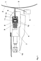
- the coating device has a driven counter roller 1, from which the material web 2 - a paper or cardboard web with a width of 8 m and more - is deflected. Excess coating material is applied to the material web 2 by a coating unit (not shown), which is doctored down to the desired coat weight by a metering system with an elastically bendable doctor knife 3 as a metering element.
- the scraper knife 3 is clamped with its foot in a clamping bar 5 which is displaceably mounted in the direction of the counter roller 1 in a scraper bar 4. It is supported on its rear side facing away from the counter roll 1 below its tip by a support bar 6 which is elastically flexible in the direction of the counter roll 1.
- the contact pressure of the scraper knife 3 against the counter roller 1 can be adjusted by moving and / or pivoting the clamping bar 5 relative to the support bar 6 which extends over the entire width of the web.
- the support bar 6 is slidably mounted in the direction of the counter roller 1 in a holder 7, 8, which consists of a base plate 7 screwed onto the scraper beam 4 and a cover plate 8 screwed onto the base plate 7.
- the holder 7, 8 has an approximately rectangular recess, which extends over the working width, and has an opening slot, from which the support bar 6 is attached with its Support edge protrudes.
- the support bar 6 is widened like a bead at its rear end above and below the height of the recess within the holder 7, 8. At its rear end facing away from the counter-roller 1, it is supported by a profile bar 9 lying flat against the upper and lower edges of the rear side, which also extends over the entire working width of the coating device.
- the widenings of the support bar 6 are narrower than the length of the free space in the holder 7, 8 between the end of the profile bar 9 and the front wall of the holder 7, 8, so that the support bar 6 is freely movable in the direction of the counter roller 1 via an adjustment path.
- set screws 10 are fastened at regular intervals and are guided through a bore in the rear wall of the base plate 7. With the set screws 10 designed as tension and compression screws, the profile strip 9 can be set locally differently over the working width at a distance from the counter roller 1.
- the contacting sides of the support bar 6 and the profile bar 9 each have a groove extending over the working width.
- a pressure hose 11 is inserted, which is connected on one side to a compressed air supply, not shown.
- the pressure hose 11 is protected by two bands 12 made of stainless spring steel, which are arranged between its front surface and the support strip 6 and its rear surface and the profile strip 9.
- Two further pressure hoses 13, 14 are inserted into the free spaces between the front wall of the base plate 7 or the cover plate 8 and the widened rear end of the support bar 6. The pressure hoses 13, 14 are thus able to press the support bar 6 away from the counter roller 1 in the direction of the profile bar 9.
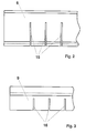
- the support bar 6 is made of a wear-resistant plastic. As shown in FIG. 2, it has slots 15 on its rear side facing away from the counter-roller 1 at regular intervals (for example every 25 mm) in order to be able to adapt to a contour as smoothly as possible.
- the profile bar 9 shown in FIG. 3 is also provided on its rear side facing away from the counter-roller 1 at regular intervals with slots 16 which also extend in the web running direction; it can be so bend in limits.
- the profile bar 9 is constructed from one piece or from a large number of individual segments and is made of metal.
- a basic position of the support bar 6 is first set using the adjusting screws 10. This takes place when the pressure hose 11 is vented while the pressure hoses 13, 14 are under pressure. Even before the web 2 is drawn into the coating device, the scraper bar 4 with the scraper knife 3 and the support bar 6 is pivoted to the counter-roller 1 and applied to this coating color by the coating unit (not shown). The thickness and uniformity of the film on the counter roller 1 is determined by the contact pressure of the doctor knife 3 u. a. adjusted with the set screws 10.
- the adjusting profile 10 is used to fine-tune the line profile on the web 2.
- the pressure hoses 13, 14 pushing away from the counter-roller 1 are vented and the pressure hose 11 is pressurized.
- the pressure in the pressure hose 11 is set such that the support bar 6 just gets into a floating state without leaving its contact with the profiling bar 9, that is to say the pressure hose 11 exactly compensates the forces pushing the scraper knife 3 away from the counter-roller 1.
- the support bar 6 is thus able to move in individual areas in the direction of the counter-roller 1 and to counteract changes automatically in order to keep the transverse profile uniform.
- the line weight is adjusted and kept constant in the web running direction in a known manner via the contact pressure of the scraper knife 3 by pivoting and / or shifting the clamping bar 5. This can be done manually or by an automatic system.
- adjustment screws 10 are used to adjust.
- the readjustment can either take place while the pressure hose 11 is under pressure or, as with the fine adjustment, while the pressure hose 11 is vented.
- the device also offers the possibility of pressurizing both hose systems (pressure hose 11 and pressure hoses 13, 14) and thus controlling the coating weight via the differential pressure. It is also possible, as with a conventional support bar, to mechanically support the pressure away from the counter-roller 1. For this purpose, the pressure hose 11 is vented and the pressure hoses 12, 13 are pressurized.
- the use of the device according to the invention for direct metering on the web 2 is described above. It can also be used to create a uniform film on a roller, which is then transferred from the roller to a web.
Landscapes
- Coating Apparatus (AREA)
- Paper (AREA)
- Machines For Manufacturing Corrugated Board In Mechanical Paper-Making Processes (AREA)
Applications Claiming Priority (2)
| Application Number | Priority Date | Filing Date | Title |
|---|---|---|---|
| DE4334556A DE4334556A1 (de) | 1993-10-11 | 1993-10-11 | Vorrichtung zum Beschichten einer Materialbahn, insbesondere einer Papier- oder Kartonbahn |
| DE4334556 | 1993-10-11 |
Publications (2)
| Publication Number | Publication Date |
|---|---|
| EP0651094A1 EP0651094A1 (de) | 1995-05-03 |
| EP0651094B1 true EP0651094B1 (de) | 1996-07-31 |
Family
ID=6499845
Family Applications (1)
| Application Number | Title | Priority Date | Filing Date |
|---|---|---|---|
| EP94115241A Expired - Lifetime EP0651094B1 (de) | 1993-10-11 | 1994-09-28 | Vorrichtung zum Beschichten einer Materialbahn, insbesondere einer Papier- oder Kartonbahn |
Country Status (5)
| Country | Link |
|---|---|
| EP (1) | EP0651094B1 (fi) |
| AT (1) | ATE140987T1 (fi) |
| DE (2) | DE4334556A1 (fi) |
| ES (1) | ES2094018T3 (fi) |
| FI (1) | FI944748A (fi) |
Families Citing this family (7)
| Publication number | Priority date | Publication date | Assignee | Title |
|---|---|---|---|---|
| DE19537781A1 (de) * | 1995-10-11 | 1997-04-17 | Leybold Ag | Beschichtungsanlage für Folien |
| DE19617458A1 (de) * | 1996-05-02 | 1997-11-06 | Jagenberg Papiertech Gmbh | Abstützsystem für das Dosierelement einer Beschichtungsvorrichtung |
| DE19626580A1 (de) * | 1996-07-02 | 1998-01-08 | Jagenberg Papiertech Gmbh | Dosiersystem für Vorrichtungen zum Beschichten von Materialbahnen, insbesondere Papier- oder Kartonbahnen |
| DE19738356A1 (de) * | 1997-09-02 | 1999-03-04 | Voith Sulzer Papiermasch Gmbh | Einrichtung zum Abstreifen oder/und Dosieren eines flüssigen bis pastösen Mediums auf einer sich vorbeibewegenden Arbeitsfläche; Stichwort: Schwimmendes Rakel |
| DE19753899A1 (de) | 1997-12-05 | 1999-06-10 | Jagenberg Papiertech Gmbh | Pneumatisch betätigbares Stellelement, insbesondere zur Regulierung des Querprofils in einer Beschichtungsvorrichtung für Papier- oder Kartonbahnen |
| DE19755411A1 (de) | 1997-12-12 | 1999-06-17 | Voith Sulzer Papiertech Patent | Rakelvorrichtung |
| DE102009002017A1 (de) * | 2009-03-31 | 2010-10-07 | Voith Patent Gmbh | Vorrichtung und Verfahren zum Beschichten von Materialbahnen, insbesondere Papier- oder Kartonbahnen |
Family Cites Families (10)
| Publication number | Priority date | Publication date | Assignee | Title |
|---|---|---|---|---|
| DE2528907A1 (de) * | 1975-06-28 | 1977-01-20 | Karl Hehl | Formenschliesseinheit mit sicherheitsabdeckung |
| DE2825907B2 (de) * | 1978-06-13 | 1981-02-26 | Jagenberg-Werke Ag, 4000 Duesseldorf | Vorrichtung zum Aufbringen einer Beschichtung auf eine Materialbahn |
| US4452833A (en) * | 1982-02-08 | 1984-06-05 | Consolidated Papers, Inc. | Paper coating method |
| DE3927329A1 (de) * | 1989-08-18 | 1991-02-21 | Jagenberg Ag | Vorrichtung zum beschichten einer um eine gegenwalze gefuehrten materialbahn |
| DE3934986A1 (de) * | 1989-10-20 | 1991-04-25 | Jagenberg Ag | Vorrichtung zum beschichten einer um eine gegenwalze gefuehrten materialbahn |
| US5077095A (en) * | 1990-05-17 | 1991-12-31 | Beloit Corporation | Flexible blade coating arrangement and method with compound blade loading |
| FI91025C (fi) * | 1991-02-08 | 1995-08-22 | Valmet Paper Machinery Inc | Menetelmä paperin tai muun rainamateriaalin päällystemäärän poikkiprofiilin säätämiseksi ja menetelmän toteuttamiseen tarkoitettu päällystysasema |
| DE9103570U1 (de) * | 1991-03-21 | 1992-07-23 | Zimmer, Johannes, Klagenfurt, Kärnten | Rakelgerät |
| DE4207731A1 (de) * | 1992-03-11 | 1993-09-16 | Jagenberg Ag | Abstuetzleiste fuer eine beschichtungsvorrichtung |
| DE4230276A1 (de) * | 1992-09-10 | 1994-03-17 | Voith Gmbh J M | Streicheinrichtung für laufende Bahnen, insbesondere Papier oder Karton |
-
1993
- 1993-10-11 DE DE4334556A patent/DE4334556A1/de not_active Withdrawn
-
1994
- 1994-09-28 EP EP94115241A patent/EP0651094B1/de not_active Expired - Lifetime
- 1994-09-28 ES ES94115241T patent/ES2094018T3/es not_active Expired - Lifetime
- 1994-09-28 DE DE59400472T patent/DE59400472D1/de not_active Expired - Fee Related
- 1994-09-28 AT AT94115241T patent/ATE140987T1/de active
- 1994-10-10 FI FI944748A patent/FI944748A/fi not_active Application Discontinuation
Also Published As
| Publication number | Publication date |
|---|---|
| ATE140987T1 (de) | 1996-08-15 |
| ES2094018T3 (es) | 1997-01-01 |
| FI944748A (fi) | 1995-04-12 |
| EP0651094A1 (de) | 1995-05-03 |
| FI944748A0 (fi) | 1994-10-10 |
| DE59400472D1 (de) | 1996-09-05 |
| DE4334556A1 (de) | 1995-04-13 |
Similar Documents
| Publication | Publication Date | Title |
|---|---|---|
| EP0307618B1 (de) | Vorrichtung zum Beschichten einer um eine Gegenwalze geführten Materialbahn | |
| AT392602B (de) | Streicheinrichtung zur beschichtung laufender warenbahnen | |
| DE2913421C3 (de) | Verfahren und Vorrichtung zum Abstreifen von überschüssiger Streichmasse von einer laufenden Bahn | |
| EP0418476B1 (de) | Vorrichtung zum Beschichten einer um eine Gegenwalze geführten Materialbahn | |
| EP0682728A1 (de) | Dosiersystem für vorrichtung zum beschichten von materialbahnen, insbesondere papier- oder kartonbahnen | |
| DE2555669C3 (de) | Vorrichtung zum Abstreifen überschüssiger Streichmasse | |
| DE4334555C2 (de) | Halterung für eine Rakelstange | |
| EP0651094B1 (de) | Vorrichtung zum Beschichten einer Materialbahn, insbesondere einer Papier- oder Kartonbahn | |
| CH668922A5 (de) | Verfahren und vorrichtung fuer die streichbeschichtung einer sich bewegenden materialbahn. | |
| AT393360B (de) | Einrichtung zur beschichtung laufender warenbahnen, insbesondere aus papier oder karton | |
| DE4014647C2 (de) | Einrichtung zum Auftragen einer Beschichtung auf eine laufende Warenbahn | |
| EP0583437B1 (de) | Abstützleiste für eine beschichtungsvorrichtung | |
| DE4401737C1 (de) | Streicheinrichtung | |
| DE3101300C2 (de) | Rakelvorrichtung | |
| DE69405469T2 (de) | Baugruppe zum Laden einer Rakelklinge | |
| EP0406529A2 (de) | Streicheinrichtung | |
| EP0831973B1 (de) | Abstützsystem für das dosierelement einer beschichtungsvorrichtung | |
| DE4208897A1 (de) | Auftragswerk zum beschichten von bahnen aus papier oder karton | |
| EP0757129B1 (de) | Auftragsystem für eine Vorrichtung zum Beschichten einer Papier- oder Kartonbahn | |
| DE9416951U1 (de) | Dosiereinrichtung | |
| DE19604934A1 (de) | Auftragsystem für eine Vorrichtung zum Beschichten einer Papier- oder Kartonbahn | |
| DE19627688A1 (de) | Dosiersystem für Vorrichtungen zum Beschichten von Materialbahnen, insbesondere Papier- oder Kartonbahnen | |
| DE3934986A1 (de) | Vorrichtung zum beschichten einer um eine gegenwalze gefuehrten materialbahn | |
| EP0920917B1 (de) | Pneumatisch betätigbares Stellelement, insbesondere zur Regulierung des Querprofils in einer Beschichtungsvorrichtung für Papier- oder Kartonbahnen | |
| DE19904112A1 (de) | Egalisier-/Dosier-Vorrichtung |
Legal Events
| Date | Code | Title | Description |
|---|---|---|---|
| PUAI | Public reference made under article 153(3) epc to a published international application that has entered the european phase |
Free format text: ORIGINAL CODE: 0009012 |
|
| AK | Designated contracting states |
Kind code of ref document: A1 Designated state(s): AT DE ES GB IT |
|
| 17P | Request for examination filed |
Effective date: 19950621 |
|
| GRAG | Despatch of communication of intention to grant |
Free format text: ORIGINAL CODE: EPIDOS AGRA |
|
| GRAH | Despatch of communication of intention to grant a patent |
Free format text: ORIGINAL CODE: EPIDOS IGRA |
|
| 17Q | First examination report despatched |
Effective date: 19951229 |
|
| GRAH | Despatch of communication of intention to grant a patent |
Free format text: ORIGINAL CODE: EPIDOS IGRA |
|
| ITF | It: translation for a ep patent filed | ||
| GRAA | (expected) grant |
Free format text: ORIGINAL CODE: 0009210 |
|
| AK | Designated contracting states |
Kind code of ref document: B1 Designated state(s): AT DE ES GB IT |
|
| REF | Corresponds to: |
Ref document number: 140987 Country of ref document: AT Date of ref document: 19960815 Kind code of ref document: T |
|
| GBT | Gb: translation of ep patent filed (gb section 77(6)(a)/1977) |
Effective date: 19960809 |
|
| REF | Corresponds to: |
Ref document number: 59400472 Country of ref document: DE Date of ref document: 19960905 |
|
| REG | Reference to a national code |
Ref country code: ES Ref legal event code: FG2A Ref document number: 2094018 Country of ref document: ES Kind code of ref document: T3 |
|
| PLBE | No opposition filed within time limit |
Free format text: ORIGINAL CODE: 0009261 |
|
| STAA | Information on the status of an ep patent application or granted ep patent |
Free format text: STATUS: NO OPPOSITION FILED WITHIN TIME LIMIT |
|
| 26N | No opposition filed | ||
| PGFP | Annual fee paid to national office [announced via postgrant information from national office to epo] |
Ref country code: AT Payment date: 19970822 Year of fee payment: 4 |
|
| PGFP | Annual fee paid to national office [announced via postgrant information from national office to epo] |
Ref country code: ES Payment date: 19970926 Year of fee payment: 4 |
|
| PG25 | Lapsed in a contracting state [announced via postgrant information from national office to epo] |
Ref country code: GB Free format text: LAPSE BECAUSE OF NON-PAYMENT OF DUE FEES Effective date: 19980928 Ref country code: AT Free format text: LAPSE BECAUSE OF NON-PAYMENT OF DUE FEES Effective date: 19980928 |
|
| PG25 | Lapsed in a contracting state [announced via postgrant information from national office to epo] |
Ref country code: ES Free format text: LAPSE BECAUSE OF NON-PAYMENT OF DUE FEES Effective date: 19980929 |
|
| GBPC | Gb: european patent ceased through non-payment of renewal fee |
Effective date: 19980928 |
|
| PGFP | Annual fee paid to national office [announced via postgrant information from national office to epo] |
Ref country code: DE Payment date: 20020907 Year of fee payment: 9 |
|
| PG25 | Lapsed in a contracting state [announced via postgrant information from national office to epo] |
Ref country code: DE Free format text: LAPSE BECAUSE OF NON-PAYMENT OF DUE FEES Effective date: 20040401 |
|
| REG | Reference to a national code |
Ref country code: ES Ref legal event code: FD2A Effective date: 19991013 |
|
| PG25 | Lapsed in a contracting state [announced via postgrant information from national office to epo] |
Ref country code: IT Free format text: LAPSE BECAUSE OF NON-PAYMENT OF DUE FEES Effective date: 20050928 |