EP0651094B1 - Apparatus for coating a web, particularly a paper or cardboard web - Google Patents
Apparatus for coating a web, particularly a paper or cardboard web Download PDFInfo
- Publication number
- EP0651094B1 EP0651094B1 EP94115241A EP94115241A EP0651094B1 EP 0651094 B1 EP0651094 B1 EP 0651094B1 EP 94115241 A EP94115241 A EP 94115241A EP 94115241 A EP94115241 A EP 94115241A EP 0651094 B1 EP0651094 B1 EP 0651094B1
- Authority
- EP
- European Patent Office
- Prior art keywords
- web
- mating roll
- strip
- holder
- rear side
- Prior art date
- Legal status (The legal status is an assumption and is not a legal conclusion. Google has not performed a legal analysis and makes no representation as to the accuracy of the status listed.)
- Expired - Lifetime
Links
- 239000011248 coating agent Substances 0.000 title claims abstract description 26
- 238000000576 coating method Methods 0.000 title claims abstract description 26
- 239000011111 cardboard Substances 0.000 title description 5
- 239000011087 paperboard Substances 0.000 title description 5
- 239000000463 material Substances 0.000 claims abstract description 7
- 230000013011 mating Effects 0.000 claims abstract 12
- 230000004075 alteration Effects 0.000 abstract 1
- 230000006835 compression Effects 0.000 description 2
- 238000007906 compression Methods 0.000 description 2
- 229910000639 Spring steel Inorganic materials 0.000 description 1
- 239000011324 bead Substances 0.000 description 1
- 230000001276 controlling effect Effects 0.000 description 1
- 238000004519 manufacturing process Methods 0.000 description 1
- 239000002184 metal Substances 0.000 description 1
- 230000001105 regulatory effect Effects 0.000 description 1
Images
Classifications
-
- D—TEXTILES; PAPER
- D21—PAPER-MAKING; PRODUCTION OF CELLULOSE
- D21H—PULP COMPOSITIONS; PREPARATION THEREOF NOT COVERED BY SUBCLASSES D21C OR D21D; IMPREGNATING OR COATING OF PAPER; TREATMENT OF FINISHED PAPER NOT COVERED BY CLASS B31 OR SUBCLASS D21G; PAPER NOT OTHERWISE PROVIDED FOR
- D21H25/00—After-treatment of paper not provided for in groups D21H17/00 - D21H23/00
- D21H25/08—Rearranging applied substances, e.g. metering, smoothing; Removing excess material
- D21H25/10—Rearranging applied substances, e.g. metering, smoothing; Removing excess material with blades
-
- B—PERFORMING OPERATIONS; TRANSPORTING
- B05—SPRAYING OR ATOMISING IN GENERAL; APPLYING FLUENT MATERIALS TO SURFACES, IN GENERAL
- B05C—APPARATUS FOR APPLYING FLUENT MATERIALS TO SURFACES, IN GENERAL
- B05C11/00—Component parts, details or accessories not specifically provided for in groups B05C1/00 - B05C9/00
- B05C11/02—Apparatus for spreading or distributing liquids or other fluent materials already applied to a surface ; Controlling means therefor; Control of the thickness of a coating by spreading or distributing liquids or other fluent materials already applied to the coated surface
- B05C11/04—Apparatus for spreading or distributing liquids or other fluent materials already applied to a surface ; Controlling means therefor; Control of the thickness of a coating by spreading or distributing liquids or other fluent materials already applied to the coated surface with blades
- B05C11/041—Apparatus for spreading or distributing liquids or other fluent materials already applied to a surface ; Controlling means therefor; Control of the thickness of a coating by spreading or distributing liquids or other fluent materials already applied to the coated surface with blades characterised by means for positioning, loading, or deforming the blades
- B05C11/042—Apparatus for spreading or distributing liquids or other fluent materials already applied to a surface ; Controlling means therefor; Control of the thickness of a coating by spreading or distributing liquids or other fluent materials already applied to the coated surface with blades characterised by means for positioning, loading, or deforming the blades allowing local positioning, loading or deforming along the blades
-
- B—PERFORMING OPERATIONS; TRANSPORTING
- B05—SPRAYING OR ATOMISING IN GENERAL; APPLYING FLUENT MATERIALS TO SURFACES, IN GENERAL
- B05C—APPARATUS FOR APPLYING FLUENT MATERIALS TO SURFACES, IN GENERAL
- B05C11/00—Component parts, details or accessories not specifically provided for in groups B05C1/00 - B05C9/00
- B05C11/02—Apparatus for spreading or distributing liquids or other fluent materials already applied to a surface ; Controlling means therefor; Control of the thickness of a coating by spreading or distributing liquids or other fluent materials already applied to the coated surface
- B05C11/04—Apparatus for spreading or distributing liquids or other fluent materials already applied to a surface ; Controlling means therefor; Control of the thickness of a coating by spreading or distributing liquids or other fluent materials already applied to the coated surface with blades
- B05C11/045—Apparatus for spreading or distributing liquids or other fluent materials already applied to a surface ; Controlling means therefor; Control of the thickness of a coating by spreading or distributing liquids or other fluent materials already applied to the coated surface with blades characterised by the blades themselves
Definitions
- the invention relates to a device for coating a material web, in particular a paper or cardboard web, according to the preamble of patent claim 1.
- devices which have an application unit (roller or nozzle application unit) with which the coating material, for. B. coating color, is applied in excess to the web.
- a metering system arranged after the applicator with a scraper knife as metering element scrapes the excess off to the desired coat weight, the height of the coat weight being adjustable via the contact pressure of the scraper knife on the counter roller.
- the scraper knife is supported below its tip by an adjacent support bar, so that its contact pressure can be varied by moving and / or pivoting the clamped scraper knife foot.
- DE-OS 39 27 329 describes a generic coating device in which piezo translators are used as adjusting elements for the support bar. According to one embodiment, springs counteract the pressing of the support bar with the piezo translators, wherein the counterforce of the springs can be adjusted.
- Supporting the scraper knife with a support bar has the advantage that there is a precisely defined support edge.
- the coating weight can be adjusted very constantly and evenly in the direction of web travel. Results once achieved can be reproduced with great accuracy, so that these systems are ideally suited for automation.
- a cross profile once set remains less constant. The cross profile must therefore be readjusted more frequently during operation.
- the invention has for its object to improve a generic coating device so that a uniform application in the web running direction as well as transverse to this can be set reproducibly, the uniformity is maintained even with changes in the coating weight.
- the invention has the further advantage that existing coating devices can be converted without major design changes.
- Profiling with adjusting elements e.g. adjusting screws
- a conventional support bar is still possible.
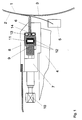
- the coating device has a driven counter roller 1, from which the material web 2 - a paper or cardboard web with a width of 8 m and more - is deflected. Excess coating material is applied to the material web 2 by a coating unit (not shown), which is doctored down to the desired coat weight by a metering system with an elastically bendable doctor knife 3 as a metering element.
- the scraper knife 3 is clamped with its foot in a clamping bar 5 which is displaceably mounted in the direction of the counter roller 1 in a scraper bar 4. It is supported on its rear side facing away from the counter roll 1 below its tip by a support bar 6 which is elastically flexible in the direction of the counter roll 1.
- the contact pressure of the scraper knife 3 against the counter roller 1 can be adjusted by moving and / or pivoting the clamping bar 5 relative to the support bar 6 which extends over the entire width of the web.
- the support bar 6 is slidably mounted in the direction of the counter roller 1 in a holder 7, 8, which consists of a base plate 7 screwed onto the scraper beam 4 and a cover plate 8 screwed onto the base plate 7.
- the holder 7, 8 has an approximately rectangular recess, which extends over the working width, and has an opening slot, from which the support bar 6 is attached with its Support edge protrudes.
- the support bar 6 is widened like a bead at its rear end above and below the height of the recess within the holder 7, 8. At its rear end facing away from the counter-roller 1, it is supported by a profile bar 9 lying flat against the upper and lower edges of the rear side, which also extends over the entire working width of the coating device.
- the widenings of the support bar 6 are narrower than the length of the free space in the holder 7, 8 between the end of the profile bar 9 and the front wall of the holder 7, 8, so that the support bar 6 is freely movable in the direction of the counter roller 1 via an adjustment path.
- set screws 10 are fastened at regular intervals and are guided through a bore in the rear wall of the base plate 7. With the set screws 10 designed as tension and compression screws, the profile strip 9 can be set locally differently over the working width at a distance from the counter roller 1.
- the contacting sides of the support bar 6 and the profile bar 9 each have a groove extending over the working width.
- a pressure hose 11 is inserted, which is connected on one side to a compressed air supply, not shown.
- the pressure hose 11 is protected by two bands 12 made of stainless spring steel, which are arranged between its front surface and the support strip 6 and its rear surface and the profile strip 9.
- Two further pressure hoses 13, 14 are inserted into the free spaces between the front wall of the base plate 7 or the cover plate 8 and the widened rear end of the support bar 6. The pressure hoses 13, 14 are thus able to press the support bar 6 away from the counter roller 1 in the direction of the profile bar 9.
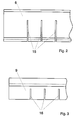
- the support bar 6 is made of a wear-resistant plastic. As shown in FIG. 2, it has slots 15 on its rear side facing away from the counter-roller 1 at regular intervals (for example every 25 mm) in order to be able to adapt to a contour as smoothly as possible.
- the profile bar 9 shown in FIG. 3 is also provided on its rear side facing away from the counter-roller 1 at regular intervals with slots 16 which also extend in the web running direction; it can be so bend in limits.
- the profile bar 9 is constructed from one piece or from a large number of individual segments and is made of metal.
- a basic position of the support bar 6 is first set using the adjusting screws 10. This takes place when the pressure hose 11 is vented while the pressure hoses 13, 14 are under pressure. Even before the web 2 is drawn into the coating device, the scraper bar 4 with the scraper knife 3 and the support bar 6 is pivoted to the counter-roller 1 and applied to this coating color by the coating unit (not shown). The thickness and uniformity of the film on the counter roller 1 is determined by the contact pressure of the doctor knife 3 u. a. adjusted with the set screws 10.
- the adjusting profile 10 is used to fine-tune the line profile on the web 2.
- the pressure hoses 13, 14 pushing away from the counter-roller 1 are vented and the pressure hose 11 is pressurized.
- the pressure in the pressure hose 11 is set such that the support bar 6 just gets into a floating state without leaving its contact with the profiling bar 9, that is to say the pressure hose 11 exactly compensates the forces pushing the scraper knife 3 away from the counter-roller 1.
- the support bar 6 is thus able to move in individual areas in the direction of the counter-roller 1 and to counteract changes automatically in order to keep the transverse profile uniform.
- the line weight is adjusted and kept constant in the web running direction in a known manner via the contact pressure of the scraper knife 3 by pivoting and / or shifting the clamping bar 5. This can be done manually or by an automatic system.
- adjustment screws 10 are used to adjust.
- the readjustment can either take place while the pressure hose 11 is under pressure or, as with the fine adjustment, while the pressure hose 11 is vented.
- the device also offers the possibility of pressurizing both hose systems (pressure hose 11 and pressure hoses 13, 14) and thus controlling the coating weight via the differential pressure. It is also possible, as with a conventional support bar, to mechanically support the pressure away from the counter-roller 1. For this purpose, the pressure hose 11 is vented and the pressure hoses 12, 13 are pressurized.
- the use of the device according to the invention for direct metering on the web 2 is described above. It can also be used to create a uniform film on a roller, which is then transferred from the roller to a web.
Landscapes
- Coating Apparatus (AREA)
- Paper (AREA)
- Machines For Manufacturing Corrugated Board In Mechanical Paper-Making Processes (AREA)
Abstract
Description
Die Erfindung betrifft eine Vorrichtung zum Beschichten einer Materialbahn, insbesondere einer Papier- oder Kartonbahn, gemäß dem Oberbegriff des Patentanspruchs 1.The invention relates to a device for coating a material web, in particular a paper or cardboard web, according to the preamble of
Zum Beschichten von Papier- oder Kartonbahnen sind Vorrichtungen bekannt, die ein Auftragwerk (Walzen- oder Düsenauftragwerk) aufweisen, mit dem das Beschichtungsmaterial, z. B. Streichfarbe, im Überschuß auf die Bahn aufgetragen wird. Ein im Anschluß an das Auftragwerk angeordnetes Dosiersystem mit einem Schabermesser als Dosierelement rakelt den Überschuß bis auf das gewünschte Strichgewicht ab, wobei sich die Höhe des Strichgewichts über den Anpreßdruck des Schabermessers an die Gegenwalze einstellen läßt. Unterhalb seiner Spitze wird das Schabermesser von einer anliegenden Abstützleiste abgestützt, dadurch läßt sich sein Anpreßdruck durch Verschieben und/oder Verschwenken des eingeklemmten Schabermesserfußes variieren.For coating paper or cardboard webs, devices are known which have an application unit (roller or nozzle application unit) with which the coating material, for. B. coating color, is applied in excess to the web. A metering system arranged after the applicator with a scraper knife as metering element scrapes the excess off to the desired coat weight, the height of the coat weight being adjustable via the contact pressure of the scraper knife on the counter roller. The scraper knife is supported below its tip by an adjacent support bar, so that its contact pressure can be varied by moving and / or pivoting the clamped scraper knife foot.
Beim Streichen von Papier- oder Kartonbahnen treten produktionsbedingte Schwankungen im Querprofil der Bahnen auf, die es erforderlich machen, den Anpreßdruck des Schabermessers über die Arbeitsbreite unterschiedlich einzustellen, um einen gleichmäßigen Strich zu erhalten. Dazu ist es aus der DE-PS 28 25 907 bekannt, eine in Grenzen biegsame Abstützleiste über Zug- und Druckschrauben entlang der Unterstützungslinie einzujustieren, je nachdem, ob das Strichgewicht an den entsprechenden Stellen zu hoch oder zu niedrig ist.When coating paper or cardboard webs, there are production-related fluctuations in the cross-section of the webs, which make it necessary to adjust the contact pressure of the doctor knife differently across the working width in order to obtain a uniform line. For this purpose, it is known from DE-PS 28 25 907 to adjust a support bar that is flexible within limits via tension and compression screws along the support line, depending on whether the coat weight is too high or too low at the corresponding points.
Die DE-OS 39 27 329 beschreibt eine gattungsgemäße Beschichtungsvorrichtung, bei der als Verstellelemente für die Abstützleiste Piezo-Translatoren eingesetzt sind. Nach einer Ausführungsform wirken Federn dem Anpressen der Abstützleiste mit den Piezo-Translatoren entgegen, wobei die Gegenkraft der Federn eingestellt werden kann.DE-OS 39 27 329 describes a generic coating device in which piezo translators are used as adjusting elements for the support bar. According to one embodiment, springs counteract the pressing of the support bar with the piezo translators, wherein the counterforce of the springs can be adjusted.
Die Abstützung des Schabermessers mit einer Abstützleiste hat den Vorteil, daß eine genau definierte Abstützkante vorliegt. In Bahnlaufrichtung läßt sich das Strichgewicht sehr konstant und gleichmäßig einstellen. Einmal erzielte Ergebnisse können mit großer Genauigkeit reproduziert werden, so daß diese Systeme für eine Automatisierung hervorragend geeignet sind. Allerdings hat sich in der Praxis gezeigt, daß ein einmal eingestelltes Querprofil weniger konstant bleibt. Das Querprofil muß daher während des Betriebs häufiger nachgestellt werden.Supporting the scraper knife with a support bar has the advantage that there is a precisely defined support edge. The coating weight can be adjusted very constantly and evenly in the direction of web travel. Results once achieved can be reproduced with great accuracy, so that these systems are ideally suited for automation. However, it has been shown in practice that a cross profile once set remains less constant. The cross profile must therefore be readjusted more frequently during operation.
Aus der DE-OS 36 12 248 ist es bekannt, anstelle mit einer Abstützleiste das Schabermesser mit einem Druckschlauch abzustützen. Die Abstützung mit einem Schlauchsystem hat den Vorteil, daß ein einmal eingestelltes Querprofil sehr konstant bleibt. Auftretende Veränderungen werden weitgehend selbstätig ausgeglichen, falls ein ausreichend hoher und konstanter Druck im Schlauch vorhanden ist. Nachteilig bei diesem System ist, daß bei einer Verstellung des Schabermessers zur Änderung des Strichgewichts es auch zu einer Verschiebung der Abstützfläche kommt, da keine genau definierte Abstützkante vorhanden ist. Daraus resultiert ein instabiles Verhalten bei einer Änderung des Strichgewichts mit der Folge, daß ein ungleichmäßiger, wellenförmiger Auftrag in Bahnlaufrichtung auftreten kann.From DE-OS 36 12 248 it is known to support the scraper knife with a pressure hose instead of with a support bar. The support with a hose system has the advantage that a cross profile once set remains very constant. Changes that occur are largely compensated for automatically if there is a sufficiently high and constant pressure in the hose. A disadvantage of this system is that when the scraper knife is adjusted to change the coating weight, the support surface is also displaced since there is no precisely defined support edge. This results in an unstable behavior when the coating weight changes, with the result that an uneven, undulating application in the web running direction can occur.
Der Erfindung liegt die Aufgabe zugrunde, eine gattungsgemäße Beschichtungsvorrichtung so zu verbessern, daß ein gleichmäßiger Auftrag sowohl in Bahnlaufrichtung als auch quer zu dieser reproduzierbar eingestellt werden kann, dessen Gleichmäßigkeit auch bei Änderungen des Strichgewichts erhalten bleibt.The invention has for its object to improve a generic coating device so that a uniform application in the web running direction as well as transverse to this can be set reproducibly, the uniformity is maintained even with changes in the coating weight.
Diese Aufgabe wird mit den Merkmalen des Patentanspruchs 1 gelöst.This object is achieved with the features of
Die Erfindung hat den weiteren Vorteil, daß bestehende Streichvorrichtungen ohne große konstruktive Änderungen umgerüstet werden können. Eine Profilierung mit Stellelementen (z. B. Stellschrauben) wie bei einer konventionellen Abstützleiste ist weiterhin noch möglich.The invention has the further advantage that existing coating devices can be converted without major design changes. Profiling with adjusting elements (e.g. adjusting screws) as with a conventional support bar is still possible.
Die Zeichnung dient zur Erläuterung der Erfindung anhand eines vereinfacht dargestellten Ausführungsbeispiels.
Figur 1- zeigt als Längsschnitt einen Ausschnitt einer Beschichtungsvorrichtung nach der Erfindung.
Figur 2- zeigt eine Draufsicht auf eine Abstützleiste.
Figur 3- zeigt eine Draufsicht auf eine Profilierleiste.
- Figure 1
- shows a longitudinal section of a section of a coating device according to the invention.
- Figure 2
- shows a plan view of a support bar.
- Figure 3
- shows a plan view of a profiling strip.
Die Beschichtungsvorrichtung weist eine angetriebene Gegenwalze 1 auf, von der die Materialbahn 2 - eine Papier- oder Kartonbahn von einer Breite von 8 m und mehr - umgelenkt wird. Auf die Materialbahn 2 wird von einem nicht dargestellten Auftragwerk Beschichtungsmaterial im Überschuß aufgetragen, das von einem Dosiersystem mit einem elastisch verbiegbaren Schabermesser 3 als Dosierelement bis auf das gewünschte Strichgewicht abgerakelt wird. Das Schabermesser 3 ist mit seinem Fuß in einem in Richtung zur Gegenwalze 1 in einen Schaberbalken 4 verschiebbar gelagerten Klemmbalken 5 festgeklemmt. Es wird an seiner der Gegenwalze 1 abgewandten Rückseite unterhalb seiner Spitze von einer in Richtung zur Gegenwalze 1 elastisch biegsamen Abstützleiste 6 abgestützt. Durch eine Verschiebung und/oder Verschwenkung des Klemmbalkens 5 relativ zu der sich über die gesamte Bahnbreite erstreckenden Abstützleiste 6 läßt sich der Anpreßdruck des Schabermessers 3 an die Gegenwalze 1 einstellen.The coating device has a driven
Die Abstützleiste 6 ist in Richtung zur Gegenwalze 1 verschiebbar in einem Halter 7, 8 gelagert, der aus einer auf dem Schaberbalken 4 festgeschraubten Grundplatte 7 und einer auf der Grundplatte 7 festgeschraubten Deckplatte 8 besteht . Dazu weist der Halter 7, 8 eine in etwa rechteckige, sich über die Arbeitsbreite erstreckende Aussparung mit einem Öffnungsschlitz auf, aus dem die Abstützleiste 6 mit ihrer Abstützkante herausragt. Die Abstützleiste 6 ist an ihrem rückwärtigen Ende oben und unten der Höhe der Aussparung innerhalb des Halters 7, 8 angepaßt wulstartig verbreitert. An ihrem der Gegenwalze 1 abgewandten rückwärtigen Ende wird sie von einer an den oberen und unteren Rändern der Rückseite flächig anliegenden Profilleiste 9 abgestützt, die sich ebenfalls über die gesamte Arbeitsbreite der Beschichtungsvorrichtung erstreckt. Die Verbreiterungen der Abstützleiste 6 sind schmaler als die Länge des Freiraums im Halter 7, 8 zwischen dem Ende der Profilleiste 9 und der vorderen Wand des Halters 7, 8, so daß die Abstützleiste 6 in Richtung zur Gegenwalze 1 über einen Stellweg freibeweglich gelagert ist. An dem der Gegenwalze 1 abgewandten Ende der Profilleiste 9 sind in regelmäßigen Abständen Stellschrauben 10 befestigt, die durch eine Bohrung in der Rückwand der Grundplatte 7 geführt sind. Mit den als Zug- und Druckschrauben ausgebildeten Stellschrauben 10 läßt sich die Profilleiste 9 über die Arbeitsbreite lokal unterschiedlich im Abstand zur Gegenwalze 1 einstellen.The
Die einander berührenden Seiten der Abstützleiste 6 und der Profilleiste 9 weisen jeweils eine sich über die Arbeitsbreite erstreckende Nut auf. In dem so gebildeten Freiraum ist ein Druckschlauch 11 eingelegt, der an einer Seite an eine nicht dargestellte Druckluftzufuhr angeschlossen ist. Der Druckschlauch 11 ist durch an zwei Bänder 12 aus rostfreiem Federbandstahl geschützt, die zwischen seiner Vorderfläche und der Abstützleiste 6 sowie seiner Rückfläche und der Profilleiste 9 angeordnet sind. Zwei weitere Druckschläuche 13, 14 sind in die Freiräume zwischen der vorderen Wand der Grundplatte 7 bzw. der Deckplatte 8 und dem verbreiterten rückwärtigen Ende der Abstützleiste 6 eingelegt. Die Druckschläuche 13, 14 sind so in der Lage, die Abstützleiste 6 von der Gegenwalze 1 weg in Richtung der Profilleiste 9 zu drücken.The contacting sides of the
Die Abstützleiste 6 ist aus einem verschleißfesten Kunststoff gefertigt. Wie in Fig. 2 dargestellt, weist sie an ihrer der Gegenwalze 1 abgewandten Rückseite in regelmäßigen Abständen (z. B. alle 25 mm) Schlitze 15 auf, um sich einer Kontur möglichst stufenlos anpassen zu können. Die in Fig. 3 gezeigte Profilleiste 9 ist ebenfalls an ihrer der Gegenwalze 1 abgewandten Rückseite in regelmäßigen Abständen mit Schlitzen 16 versehen, die sich ebenfalls in Bahnlaufrichtung erstrecken; sie läßt sich so in Grenzen verbiegen. Die Profilleiste 9 ist aus einem Stück oder aus einer Vielzahl von Einzelsegmenten aufgebaut und aus Metall gefertigt.The
Vor Beginn des Beschichtens wird zunächst mit den Stellschrauben 10 eine Grundstellung der Abstützleiste 6 eingestellt. Dies erfolgt bei entlüftetem Druckschlauch 11 während die Druckschläuche 13, 14 unter Druck stehen. Noch bevor die Bahn 2 in die Beschichtungsvorrichtung eingezogen ist, wird der Schaberbalken 4 mit dem Schabermesser 3 und der Abstützleiste 6 an die Gegenwalze 1 geschwenkt und auf diese Streichfarbe von dem nicht dargestellten Auftragwerk aufgetragen. Die Dicke und Gleichmäßigkeit des Films auf der Gegenwalze 1 wird über den Anpreßdruck des Schabermessers 3 u. a. mit den Stellschrauben 10 einjustiert.Before the start of coating, a basic position of the
Anschließend wird die Gegenwalze 1 gereinigt und die Bahn 2 in die Beschichtungsvorrichtung eingezogen, so daß sie auf der Gegenwalze 1 aufliegt. Nach erneutem Starten des Auftragswerks erfolgt mit den Stellschrauben 10 die Feineinstellung des Strichprofils auf der Bahn 2. Ist ein optimales Profil erreicht, werden die von der Gegenwalze 1 wegdrückenden Druckschläuche 13, 14 entlüftet und der Druckschlauch 11 wird unter Druck gesetzt. Der Druck im Druckschlauch 11 wird so eingestellt, daß die Abstützleiste 6 ohne ihre Anlage an der Profilierleiste 9 zu verlassen soeben in einen schwimmenden Zustand gerät, also der Druckschlauch 11 exakt die das Schabermesser 3 von der Gegenwalze 1 wegdrückenden Kräfte kompensiert. Die Abstützleiste 6 ist so in der Lage, sich in einzelnen Bereichen in Richtung zur Gegenwalze 1 zu bewegen und Veränderungen selbstätig entgegenzuwirken, um das Querprofil gleichmäßig zu halten.Then the
Die Einstellung und Konstanthaltung des Strichgewichts in Bahnlaufrichtung erfolgt auf bekannte Weise über den Anpreßdruck des Schabermessers 3 durch eine Verschwenkung und/oder Verschiebung des Klemmbalkens 5. Dies kann von Hand oder durch eine Automatik erfolgen.The line weight is adjusted and kept constant in the web running direction in a known manner via the contact pressure of the
Werden die auftretenden Unregelmäßigkeiten zu groß, so daß sich das Querprofil nicht mehr selbstätig reguliert, wird mittels der Stellschrauben 10 nachgestellt. Die Nachstellung kann entweder erfolgen, während der Druckschlauch 11 unter Druck steht oder wie bei der Feineinstellung, während der Druckschlauch 11 entlüftet ist.If the irregularities that occur become too large, so that the cross section is no longer regulated automatically, adjustment screws 10 are used to adjust. The readjustment can either take place while the
Die Vorrichtung bietet auch die Möglichkeit, beide Schlauchsysteme (Druckschlauch 11 und Druckschläuche 13, 14) unter Druck zu setzen und so das Strichgewicht über den Differenzdruck zu steuern. Ebenso ist es möglich, wie bei einer konventionellen Abstützleiste, den Druck von der Gegenwalze 1 weg starr mechanisch abzustützen. Dazu wird der Druckschlauch 11 entlüftet und die Druckschläuche 12, 13 werden unter Druck gesetzt.The device also offers the possibility of pressurizing both hose systems (
Vorstehend ist der Einsatz der erfindungsgemäßen Vorrichtung zum direkten Dosieren auf der Bahn 2 beschrieben. Ebenso läßt sie sich einsetzen, um einen gleichmäßigen Film auf einer Walze zu erzeugen, der anschließend von der Walze an eine Bahn übertragen wird.The use of the device according to the invention for direct metering on the
Claims (2)
- Device for coating a moving material web (2), in particular a paper or board web, having a mating roll (1) which preferably deflects the web (2), having a doctor blade (3) which can be pressed onto the mating roll (1), and having a supporting strip (6) which is resiliently flexible over its length, supports the doctor blade (3) on its rear side facing away from the mating roll (1) and is mounted in a holder (7, 8) so that it can move in the direction of the mating roll (1), and whose supporting edge can be set locally differently over the working width by means of a row of adjusting elements (10), characterized in that the supporting strip (6)- is mounted in the holder (7, 8) such that it can move freely in the direction of the mating roll (1) over an adjustment range,- is supported on its rear side by a flexible profiling strip (9), which can be displaced towards the mating roll (1), and on whose rear side the adjusting elements (10) engage, and- in that a pressure hose (11), which extends over the working width, is arranged between the profiling strip (9) and the supporting strip (6).
- Device according to Claim 1, characterized in that the rear end of the supporting strip (6), which end is mounted in the holder (7, 8), has a broadening and at least one further pressure hose (13, 14), which presses the supporting strip (6) away from the mating roll (1), is arranged between the broadening and a front wall of the holder (7, 8).
Applications Claiming Priority (2)
| Application Number | Priority Date | Filing Date | Title |
|---|---|---|---|
| DE4334556A DE4334556A1 (en) | 1993-10-11 | 1993-10-11 | Device for coating a material web, in particular a paper or cardboard web |
| DE4334556 | 1993-10-11 |
Publications (2)
| Publication Number | Publication Date |
|---|---|
| EP0651094A1 EP0651094A1 (en) | 1995-05-03 |
| EP0651094B1 true EP0651094B1 (en) | 1996-07-31 |
Family
ID=6499845
Family Applications (1)
| Application Number | Title | Priority Date | Filing Date |
|---|---|---|---|
| EP94115241A Expired - Lifetime EP0651094B1 (en) | 1993-10-11 | 1994-09-28 | Apparatus for coating a web, particularly a paper or cardboard web |
Country Status (5)
| Country | Link |
|---|---|
| EP (1) | EP0651094B1 (en) |
| AT (1) | ATE140987T1 (en) |
| DE (2) | DE4334556A1 (en) |
| ES (1) | ES2094018T3 (en) |
| FI (1) | FI944748A (en) |
Families Citing this family (7)
| Publication number | Priority date | Publication date | Assignee | Title |
|---|---|---|---|---|
| DE19537781A1 (en) * | 1995-10-11 | 1997-04-17 | Leybold Ag | Coating line for foils |
| DE19617458A1 (en) * | 1996-05-02 | 1997-11-06 | Jagenberg Papiertech Gmbh | Support system for the dosing element of a coating device |
| DE19626580A1 (en) * | 1996-07-02 | 1998-01-08 | Jagenberg Papiertech Gmbh | Metering rod system for a coater for web products such as paper |
| DE19738356A1 (en) * | 1997-09-02 | 1999-03-04 | Voith Sulzer Papiermasch Gmbh | Device for stripping and / or dosing a liquid to pasty medium on a moving work surface; Keyword: floating squeegee |
| DE19753899A1 (en) | 1997-12-05 | 1999-06-10 | Jagenberg Papiertech Gmbh | Pneumatically actuated control element, in particular for regulating the cross profile in a coating device for paper or cardboard webs |
| DE19755411A1 (en) * | 1997-12-12 | 1999-06-17 | Voith Sulzer Papiertech Patent | Doctor device |
| DE102009002017A1 (en) * | 2009-03-31 | 2010-10-07 | Voith Patent Gmbh | Apparatus and method for coating webs, especially paper or board webs |
Family Cites Families (10)
| Publication number | Priority date | Publication date | Assignee | Title |
|---|---|---|---|---|
| DE2528907A1 (en) * | 1975-06-28 | 1977-01-20 | Karl Hehl | Safety shield for injection moulding machine - with device for preventing mould closure if protective shield does not function |
| DE2825907B2 (en) * | 1978-06-13 | 1981-02-26 | Jagenberg-Werke Ag, 4000 Duesseldorf | Device for applying a coating to a material web |
| US4452833A (en) * | 1982-02-08 | 1984-06-05 | Consolidated Papers, Inc. | Paper coating method |
| DE3927329A1 (en) * | 1989-08-18 | 1991-02-21 | Jagenberg Ag | DEVICE FOR COATING A MATERIAL RAIL THROUGH A COUNTER ROLLER |
| DE3934986A1 (en) * | 1989-10-20 | 1991-04-25 | Jagenberg Ag | Doctor blade adjustment - has setting motor with selective coupling to adjustment units for local and automatic setting while working |
| US5077095A (en) * | 1990-05-17 | 1991-12-31 | Beloit Corporation | Flexible blade coating arrangement and method with compound blade loading |
| FI91025C (en) * | 1991-02-08 | 1995-08-22 | Valmet Paper Machinery Inc | Method for adjusting the cross-sectional profile of the amount of paper or other web material and a coating station for carrying out the method |
| DE9103570U1 (en) * | 1991-03-21 | 1992-07-23 | Zimmer, Johannes, Klagenfurt, Kärnten | Squeegee device |
| DE4207731A1 (en) * | 1992-03-11 | 1993-09-16 | Jagenberg Ag | SUPPORT BAR FOR A COATING DEVICE |
| DE4230276A1 (en) * | 1992-09-10 | 1994-03-17 | Voith Gmbh J M | Coating device for running webs, especially paper or cardboard |
-
1993
- 1993-10-11 DE DE4334556A patent/DE4334556A1/en not_active Withdrawn
-
1994
- 1994-09-28 ES ES94115241T patent/ES2094018T3/en not_active Expired - Lifetime
- 1994-09-28 DE DE59400472T patent/DE59400472D1/en not_active Expired - Fee Related
- 1994-09-28 EP EP94115241A patent/EP0651094B1/en not_active Expired - Lifetime
- 1994-09-28 AT AT94115241T patent/ATE140987T1/en active
- 1994-10-10 FI FI944748A patent/FI944748A/en not_active Application Discontinuation
Also Published As
| Publication number | Publication date |
|---|---|
| FI944748A (en) | 1995-04-12 |
| ATE140987T1 (en) | 1996-08-15 |
| EP0651094A1 (en) | 1995-05-03 |
| DE4334556A1 (en) | 1995-04-13 |
| ES2094018T3 (en) | 1997-01-01 |
| DE59400472D1 (en) | 1996-09-05 |
| FI944748A0 (en) | 1994-10-10 |
Similar Documents
| Publication | Publication Date | Title |
|---|---|---|
| EP0307618B1 (en) | Apparatus for coating a web material moving around a counter roll | |
| AT392602B (en) | COATING DEVICE FOR COATING RUNNING PRODUCTS | |
| DE2913421C3 (en) | Method and device for stripping off excess coating material from a moving web | |
| EP0418476B1 (en) | Apparatus for coating a webmaterial moving around a counter roll | |
| WO1995016074A1 (en) | Metering system for devices for coating materials webs, especially paper or cardboard webs | |
| DE2555669C3 (en) | Device for scraping off excess coating | |
| DE4334555C2 (en) | Mount for a squeegee rod | |
| EP0651094B1 (en) | Apparatus for coating a web, particularly a paper or cardboard web | |
| CH668922A5 (en) | METHOD AND DEVICE FOR COATING A MOVING MATERIAL. | |
| AT393360B (en) | DEVICE FOR COATING CONTINUOUS GOODS, ESPECIALLY MADE OF PAPER OR CARDBOARD | |
| DE4014647C2 (en) | Device for applying a coating to a running web | |
| EP0583437B1 (en) | Pressure strip for coating device | |
| DE4401737C1 (en) | Coating device | |
| DE3101300C2 (en) | Squeegee device | |
| DE69405469T2 (en) | Assembly for loading a doctor blade | |
| EP0406529A2 (en) | Coating device | |
| EP0831973B1 (en) | Supporting system for the metering component of a coating device | |
| DE4208897A1 (en) | APPLICATION TOOL FOR COATING PAPERS OR CARDBOARDS | |
| EP0757129B1 (en) | Application system for a device for coating a paper or paperboard sheet | |
| DE9416951U1 (en) | Dosing device | |
| DE19604934A1 (en) | Application system for a device for coating a paper or cardboard web | |
| DE19627688A1 (en) | System for metering a coating on a web product, especially paper or board | |
| DE3934986A1 (en) | Doctor blade adjustment - has setting motor with selective coupling to adjustment units for local and automatic setting while working | |
| EP0920917B1 (en) | Pneumatically actuated controlling element, in particular for adjusting the transverse coating profile in apparatus for coating webs of paper or cardboard | |
| DE19904112A1 (en) | Web coating station has two setting units to position the doctor blade upstream and downstream of it acting at different points from the blade edge to use less energy with a relatively high response speed |
Legal Events
| Date | Code | Title | Description |
|---|---|---|---|
| PUAI | Public reference made under article 153(3) epc to a published international application that has entered the european phase |
Free format text: ORIGINAL CODE: 0009012 |
|
| AK | Designated contracting states |
Kind code of ref document: A1 Designated state(s): AT DE ES GB IT |
|
| 17P | Request for examination filed |
Effective date: 19950621 |
|
| GRAG | Despatch of communication of intention to grant |
Free format text: ORIGINAL CODE: EPIDOS AGRA |
|
| GRAH | Despatch of communication of intention to grant a patent |
Free format text: ORIGINAL CODE: EPIDOS IGRA |
|
| 17Q | First examination report despatched |
Effective date: 19951229 |
|
| GRAH | Despatch of communication of intention to grant a patent |
Free format text: ORIGINAL CODE: EPIDOS IGRA |
|
| ITF | It: translation for a ep patent filed | ||
| GRAA | (expected) grant |
Free format text: ORIGINAL CODE: 0009210 |
|
| AK | Designated contracting states |
Kind code of ref document: B1 Designated state(s): AT DE ES GB IT |
|
| REF | Corresponds to: |
Ref document number: 140987 Country of ref document: AT Date of ref document: 19960815 Kind code of ref document: T |
|
| GBT | Gb: translation of ep patent filed (gb section 77(6)(a)/1977) |
Effective date: 19960809 |
|
| REF | Corresponds to: |
Ref document number: 59400472 Country of ref document: DE Date of ref document: 19960905 |
|
| REG | Reference to a national code |
Ref country code: ES Ref legal event code: FG2A Ref document number: 2094018 Country of ref document: ES Kind code of ref document: T3 |
|
| PLBE | No opposition filed within time limit |
Free format text: ORIGINAL CODE: 0009261 |
|
| STAA | Information on the status of an ep patent application or granted ep patent |
Free format text: STATUS: NO OPPOSITION FILED WITHIN TIME LIMIT |
|
| 26N | No opposition filed | ||
| PGFP | Annual fee paid to national office [announced via postgrant information from national office to epo] |
Ref country code: AT Payment date: 19970822 Year of fee payment: 4 |
|
| PGFP | Annual fee paid to national office [announced via postgrant information from national office to epo] |
Ref country code: ES Payment date: 19970926 Year of fee payment: 4 |
|
| PG25 | Lapsed in a contracting state [announced via postgrant information from national office to epo] |
Ref country code: GB Free format text: LAPSE BECAUSE OF NON-PAYMENT OF DUE FEES Effective date: 19980928 Ref country code: AT Free format text: LAPSE BECAUSE OF NON-PAYMENT OF DUE FEES Effective date: 19980928 |
|
| PG25 | Lapsed in a contracting state [announced via postgrant information from national office to epo] |
Ref country code: ES Free format text: LAPSE BECAUSE OF NON-PAYMENT OF DUE FEES Effective date: 19980929 |
|
| GBPC | Gb: european patent ceased through non-payment of renewal fee |
Effective date: 19980928 |
|
| PGFP | Annual fee paid to national office [announced via postgrant information from national office to epo] |
Ref country code: DE Payment date: 20020907 Year of fee payment: 9 |
|
| PG25 | Lapsed in a contracting state [announced via postgrant information from national office to epo] |
Ref country code: DE Free format text: LAPSE BECAUSE OF NON-PAYMENT OF DUE FEES Effective date: 20040401 |
|
| REG | Reference to a national code |
Ref country code: ES Ref legal event code: FD2A Effective date: 19991013 |
|
| PG25 | Lapsed in a contracting state [announced via postgrant information from national office to epo] |
Ref country code: IT Free format text: LAPSE BECAUSE OF NON-PAYMENT OF DUE FEES Effective date: 20050928 |