EP0650165B1 - Plattenkassette - Google Patents
Plattenkassette Download PDFInfo
- Publication number
- EP0650165B1 EP0650165B1 EP95100146A EP95100146A EP0650165B1 EP 0650165 B1 EP0650165 B1 EP 0650165B1 EP 95100146 A EP95100146 A EP 95100146A EP 95100146 A EP95100146 A EP 95100146A EP 0650165 B1 EP0650165 B1 EP 0650165B1
- Authority
- EP
- European Patent Office
- Prior art keywords
- shutter
- disc
- cartridge
- opening
- receiving
- Prior art date
- Legal status (The legal status is an assumption and is not a legal conclusion. Google has not performed a legal analysis and makes no representation as to the accuracy of the status listed.)
- Expired - Lifetime
Links
- 238000003780 insertion Methods 0.000 claims description 45
- 230000037431 insertion Effects 0.000 claims description 45
- 230000002093 peripheral effect Effects 0.000 claims description 11
- 239000004576 sand Substances 0.000 claims 1
- 230000007246 mechanism Effects 0.000 description 6
- 230000003287 optical effect Effects 0.000 description 5
- 238000000638 solvent extraction Methods 0.000 description 5
- 239000002184 metal Substances 0.000 description 4
- 239000011347 resin Substances 0.000 description 4
- 229920005989 resin Polymers 0.000 description 4
- 230000015572 biosynthetic process Effects 0.000 description 3
- 238000000576 coating method Methods 0.000 description 3
- 238000011109 contamination Methods 0.000 description 3
- 239000011248 coating agent Substances 0.000 description 2
- 230000008878 coupling Effects 0.000 description 2
- 238000010168 coupling process Methods 0.000 description 2
- 238000005859 coupling reaction Methods 0.000 description 2
- 239000002390 adhesive tape Substances 0.000 description 1
- 230000006835 compression Effects 0.000 description 1
- 238000007906 compression Methods 0.000 description 1
- 238000010276 construction Methods 0.000 description 1
- 230000007547 defect Effects 0.000 description 1
- 238000001514 detection method Methods 0.000 description 1
- 230000003292 diminished effect Effects 0.000 description 1
- 238000006073 displacement reaction Methods 0.000 description 1
- 230000007257 malfunction Effects 0.000 description 1
- 230000004048 modification Effects 0.000 description 1
- 238000012986 modification Methods 0.000 description 1
- 230000000717 retained effect Effects 0.000 description 1
- 229910001220 stainless steel Inorganic materials 0.000 description 1
- 239000010935 stainless steel Substances 0.000 description 1
Images


Classifications
-
- G—PHYSICS
- G11—INFORMATION STORAGE
- G11B—INFORMATION STORAGE BASED ON RELATIVE MOVEMENT BETWEEN RECORD CARRIER AND TRANSDUCER
- G11B23/00—Record carriers not specific to the method of recording or reproducing; Accessories, e.g. containers, specially adapted for co-operation with the recording or reproducing apparatus ; Intermediate mediums; Apparatus or processes specially adapted for their manufacture
- G11B23/02—Containers; Storing means both adapted to cooperate with the recording or reproducing means
- G11B23/03—Containers for flat record carriers
- G11B23/0301—Details
- G11B23/031—Indicating means, e.g. sticker, bar code
-
- G—PHYSICS
- G11—INFORMATION STORAGE
- G11B—INFORMATION STORAGE BASED ON RELATIVE MOVEMENT BETWEEN RECORD CARRIER AND TRANSDUCER
- G11B17/00—Guiding record carriers not specifically of filamentary or web form, or of supports therefor
- G11B17/02—Details
- G11B17/04—Feeding or guiding single record carrier to or from transducer unit
- G11B17/041—Feeding or guiding single record carrier to or from transducer unit specially adapted for discs contained within cartridges
- G11B17/043—Direct insertion, i.e. without external loading means
- G11B17/0436—Direct insertion, i.e. without external loading means with opening mechanism of the cartridge shutter
-
- G—PHYSICS
- G11—INFORMATION STORAGE
- G11B—INFORMATION STORAGE BASED ON RELATIVE MOVEMENT BETWEEN RECORD CARRIER AND TRANSDUCER
- G11B23/00—Record carriers not specific to the method of recording or reproducing; Accessories, e.g. containers, specially adapted for co-operation with the recording or reproducing apparatus ; Intermediate mediums; Apparatus or processes specially adapted for their manufacture
- G11B23/02—Containers; Storing means both adapted to cooperate with the recording or reproducing means
- G11B23/03—Containers for flat record carriers
- G11B23/0301—Details
- G11B23/0302—Auxiliary features
- G11B23/0303—Write protect features with a sliding part
-
- G—PHYSICS
- G11—INFORMATION STORAGE
- G11B—INFORMATION STORAGE BASED ON RELATIVE MOVEMENT BETWEEN RECORD CARRIER AND TRANSDUCER
- G11B23/00—Record carriers not specific to the method of recording or reproducing; Accessories, e.g. containers, specially adapted for co-operation with the recording or reproducing apparatus ; Intermediate mediums; Apparatus or processes specially adapted for their manufacture
- G11B23/02—Containers; Storing means both adapted to cooperate with the recording or reproducing means
- G11B23/03—Containers for flat record carriers
- G11B23/0301—Details
- G11B23/0308—Shutters
Definitions
- the present invention relates to a disc cartridge according to the preamble of claim 1.
- a magnetic disc or an optical disc is encased in a cassette case made of two shell halves.
- a hole into which a spindle for rotating the disc is to be inserted is formed in a central portion of the cassette case.
- Head insertion holes into which a write and read head is to be inserted is formed in the cassette case so as to extend in the radial direction to traverse the recording surface of the disc.
- Such a disc cartridge is shown in, for example, Japanese Utility Model Unexamined Publication No. 62-168176.
- This cartridge has a shell for encasing the disc.
- a spindle hole is formed in the central portion of the shell half.
- a hub formed in the central portion of the disc is located in the spindle hole of each shell half.
- the spindle of the recording and reproducing apparatus is to be located at the hub which is sucked by a turntable.
- the head insertion holes are formed on an insertion side of the cartridge relative to the recording and reproducing apparatus.
- a write and read head (pickup head) is inserted into one of the head insertion holes.
- the head insertion holes are closed and opened by sliding movement of the shutter.
- the shutter is bent at its intermediate portion so as to extend to the top and bottom of the cartridge to cover the head insertion holes and two spindle holes.
- the shutter On the insertion side of the cartridge into the recording and reproducing apparatus, the shutter is slidingly moved along a guide portion of the cartridge front edge to open and close the insertion holes and the spindle holes.
- the shutter is made of metal
- the cartridge is made of plastic. Therefore, when the shutter is frequently moved on and along the cartridge, frictional or abraded chips are generated due to the sliding movement between the metal and plastic. The chips would enter through the openings of the cartridge into the interior thereof to stick or adhere to the disc.
- EP 0 250 111 discloses a cartridge for an optical disc for recording data on the two faces thereof and an associated reading device.
- a simple construction of the cartridge is provided which enables the associated reading device to open the shutter of said cartridge in opposite directions with only one single member.
- a cartridge C for an optical disc has a cartridge case 1 which is composed of upper and lower shell halves 2 and 3 in alignment with each other.
- a spindle hole 4 is formed in the central portion of the case 1, the spindle hole 4 being integrally formed with a head insertion hole 5.
- a lower end of the shutter 6 is guided by a retainer plate 6.
- Double writing preventing portions 9a and 9b are provided on the right and left sides on the rear edge side in the insertion direction to the recording and reproducing apparatus for the cartridge C.
- a shutter 6 is bent at the front edge of the case 1 to extend to the bottom side.
- a return coil spring 10 is encased on the left side of the case 1, so that the shutter 6 is biased in the direction to close the holes 4 and 5.
- the shutter plate 6 is formed of a single metal sheet such as a stainless plate as shown in Fig. 2.
- a shutter 6 is provided with two planar plates 11, 11 confronted with each other and a head portion 13 defined by a connecting portion of the planar plates 11, 11.
- a slide portion is formed in a lower portion of each planar plate 11 so as to slidingly engage with the retainer plate 8.
- the head portion 13 is fixed by screws 15, 15 for covering an elongated slider 14.
- the screws 15, 15 are threadedly engaged with receiving holes 18, 18 of the slider 14 through openings 18, 18.
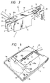
- An opening and closing pin receiving hole 17 into which an opening and closing pin P1 is formed on a drive side of the recording and reproducing apparatus is inserted is formed in a tail portion of the head portion 13 (Fig. 3).
- a receiving recess 19 is formed in the slider 14 corresponding to the opening and closing pin receiving hole 17.
- the opening and closing pin P1 mounted on an arm 30 as shown in Fig. 3 is engaged with the receiving recess 19.
- Guide grooves 21, 21 are formed in both sides of the slider 14 and are adapted to engage with guide rails 22, 22 (Fig. 2) formed in a guide portion G formed at a front edge of the cartridge C on the recording and reproducing side as shown in Fig. 3.
- a slanted surface 20 is formed at a front face of the slider 14.
- the slanted surface 20 serves to assist a smooth passage of an opening and closing pin P2 mounted on an arm 31 on the drive side of the recording and reproducing apparatus as shown in Fig. 3.
- one of the opening and closing pins P1 and P2 is inserted into the receiving recess 19 of the slider 14 and the receiving hole 17 of the shutter 6.
- the opening and closing pin P1 moves the shutter 6 leftwardly to open the spindle holes 4 and the head insertion holes 5 as shown in Fig. 4
- the other opening and closing pin P2 rides over and along the slanted surface 20 of the slider 14 so that the pins P1 and P2 cross with each other.
- pins P1 and P2 cross with each other.
- a so-called disposal pin i.e., the unnecessary opening and closing pin P2 is smoothly guided.
- the slider 14 is engaged with the guide portion G at the front edge of the cartridge C on the recording and reproducing apparatus side, and the shutter 6 is held to the slider 14. Therefore, when the shutter 6 is frequently moved by the opening and closing pin P1 for the opening and closing operation, the slider 14 made of plastic is engaged with a guide portion G made of plastic, so that any cut chips will not be generated by the sliding contact therebetween. Thus, there is no fear that the disc would be contaminated. Also, even if the cartridge C is protect the shutter 6. Thus, the shutter 6 is prevented effectively from being separated apart from the cartridge.
- a recess 30' As shown in Fig. 5.
- a slanted surface 30a is formed in an inner side of the recess 30'.
- a distal end 10a of the coil spring 10 is retained in a receiving portion 33 on the inner side of the slanted surface 30a.
- the distal end 10a of the coil spring 10 is received on the slanted surface 30a through a cutout 32 formed in a planar portion 31' of the slider 14.
- a projection 31a is formed on an inner surface of the planar portion 31' and the distal end 10a of the coil spring 10 extends through the cutout 32.
- the projection 31a has a slanted surface So.
- the projection 31a serves to smoothly guide the distal end 10a into a receiving portion 33a and simultaneously to retain the distal end 10a at the receiving portion 33a against the collision transmitted from the outside.
- a receiving space S for the return coil spring 10 is substantially in the form of a rectangular shape.
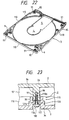
- the coil spring 10 is composed of a coiled elastic portion 41, and two arms 42 and 43 extending laterally from the coiled portion 41.
- the arm 43 is composed of a first extension portion 43a extending substantially along a peripheral wall W1 formed around a circumferential edge of the optical disc (not shown) in the case 1, and a second extension portion 43b extending from the first extension portion 43a along the front edge wall W2 of the cartridge.
- the second extension portion 43b is composed of a longitudinal portion 43b1, a laterally extending portion 43b2 bent from the portion 43b1 in the horizontal direction, and a retainer portion 43b3 engaged with an end portion of the slider 14 and bent at a right angle from the laterally extending portion 43b2 for guiding the shutter 6.
- the arm 42 is composed of a third extension portion 42a extending toward the front wall of the cartridge from the coiled portion 41, and a fourth extension portion 42b extending generally in the lateral direction from the third extension portion 42a.
- the fourth extension portion 42b is composed of crest-shape forming portions 42b1 and 42b2 for forming the crest shape on the left side in Fig. 9 extended from the third extension portion 42a, a jump portion 42b3 extending toward the front wall W2 of the cartridge from the crest-shape forming portion 42b2, and a retainer portion 42b4 extended from the jump portion 42b3 and curved at a right angle for engaging with a end wall W3 of the cartridge.
- Fig. 10 is a view as viewed in the direction indicated by the arrow A in Fig. 8.
- the slider 14 is moved along the guide rails 22, 22 of the halves 2, 3.
- An opening 0 is formed in a front face of the upper and lower halves 2 and 3.
- the coil spring 10 is inserted from the opening 0 while the one end of the spring 10 is being engaged with the side wall W3 by the end of the slider 14 in the final step of the assembling operation.
- receiving portions 33, 33b for detachably receiving the spring retainer portions 42b4 and 43b3 are formed in the slider end portion and the side wall W3, respectively.
- the central portion of the coiled portion 41 of the spring 10 is reciprocatingly moved along a locus B.
- the coiled portion 41 is moved along the circumferential wall W1 without colliding against the latter W1.
- the arms 42 and 43 are bent as described above, the coiled portion 41 is swayed in the lateral direction in accordance with the leftward movement of the slider 14, so that the reduction in opening angle óo (see Fig. 8) defined by the arms 42 and 43 may be kept at a low level even if the distance of the lateral movement of the slide 14 is increased.
- the return spring 10 is structured as described above, even if the receiving space S for the return coil spring is small, it is possible to increase the movement range of the shutter, thereby making the cartridge more compact and ensuring the smooth and large opening and closing operation of the shutter.
- a radius r at the bent portion between the crest shaped portion 42b1 and the third extension portion 4a be in the range of 0.8 to 3 mm.
- the coil spring 10 could function normally after repeated opening and closing operations of the shutter over 100,000 times. If the radius r would be too small, the durability would be lowered, whereas if the radius r would be too large, the movement during the expansion and compression of the spring would be changed according to every spring. In the latter case, it would be difficult to control the spring property in a prescribed manner.
- the projected portion of the slider 14 is composed of a horizontal portion H extending in a flush manner with the end face of the head portion 13, and a slanted surface 14a lowered gradually from the horizontal portion H (Fig. 12).
- one P1 of the opening and closing pins P1, P2 thereof is inserted through a cutout 17 of the shutter 6 into the receiving recess 19 of the slider 14.
- the opening and closing pin P1 moves the shutter 6 in the leftward direction as shown in Fig. 12 to open the head insertion holes and the spindle insertion holes
- the other opening and closing pin P2 is slidingly moved along the slanted surface 14a of the slider 14 toward the head portion 13.
- the opening and closing pin P2 is raised along the slanted surface and is deflected in the horizontal direction, to pass through the connection portion L. Therefore, the movement of the opening and closing pin P2 is smoothly effected (Fig. 13).
- both the pins P1 and P2 are crossed with each other, so that a so-called disposal pin, i.e., the unnecessary opening and closing pin P2 is smoothly guided.
- the pin P2 is apt to fall over the connection portion L.
- the slider 14 has a horizontal extension H between the slanted surface 14a and the connection portion L. Accordingly, the pin P2 can pass by the connection portion L in the horizontal direction. Thus, the movement of the opening and closing pin is stably attained so that the shutter movement is also smoothly attained.
- the head portion 13 of the shutter 6 is fixed by suitable means such as screw fastening or melt-adhesion, so that the positional relationship between the opening 27 and the recess 19 meets the following requirements.
- a side face F2 on the pressing drive side where the opening and closing pin P1 in the receiving recess 19 moves the slider 14 is located to project from a corresponding drive face F1 of the opening 27, in a direction opposite to a direction in which the opening and closing pin P1 moves the slider 14.
- the end face F1 of the opening 27 is located to be retracted from an inlet of the receiving recess 19.
- the opening and closing pin P1 may engage with or disengage from the opening 27 and the recess 19 as desired, as shown in Fig. 14.
- the drive end face F2 of the receiving recess 19 of the slider 14 for engaging with the opening and closing pin P1 of the recording and reproducing apparatus is located to a position projecting from the corresponding cutout surface F1 of the opening 27 in the direction opposite to the direction where the pin P1 moves the shutter 6. It is therefore possible to carry out the engagement and disengagement among the opening and closing pin, the opening 27 and the receiving recess 19. This would lead to the smooth and quick opening and closing operation of the shutter.
- Fig. 15 shows a modification to the mounting structure for the shutter 6 shown in Fig. 2.
- the connection portion between the shutter 6 and the slider 14 is so constructed that each engagement projection 59 formed in the shutter 6 is confronted with and engaged with an associated engagement recess 18.
- an opening 59a In the central portion of the engagement projection 59, there is formed an opening 59a through which a fastening screw 53 is inserted.
- the screw 53 is composed of a head portion 52 and a threaded portion 53a extending from the head portion 52.
- the head portion 52 is in the form of an inverted truncated cone having a slanted surface 60.
- a receiving groove into which a cross-head screw is to be inserted.
- the slider 14 When the shutter 6 and the slider 14 are coupled to each other, the slider 14 is inserted into a slider connecting portion 61 of the shutter 6, and the engagement projection 59 is engaged with the engagement recess 18 of the slider 14 in confronted relation. At this time, the threaded hole 55 of the slider 14 is in alignment with the opening 59a of the engagement projection 59 in a fixed positional relation. Under this condition, the screw 53 is inserted into the threaded hole 55. Upon the fastening operation of the screw 53, since the slanted surface 60 of the head portion 52 is brought only into contact with a peripheral portion of the opening hole 59a, even if the head portion 52 is firmly fastened, there is no fear that the positional relationship between the slider 14 and the shutter 6 would be displaced.
- the shutter 70 has opening and closing plate portions 76, 76 formed to suspend from a guide plate portion 71.
- the opening and closing plate portion 76 are in the form of a barrel shape whose central portions are expanded outwardly.
- Each of the opening and closing plate portions 76 is provided at a lower end with a guide end plate portion 77 which is to be inserted into the retainer plate 8 fixed to the cartridge in the transverse direction.
- the opening and closing plate portions 76 are expanded in an arcuate manner such that the central portions are raised from the sliding surfaces of the cartridge made of plastic within a certain reference level. Accordingly, when the shutter is slidingly moved in the lateral direction, it is possible to effectively prevent any collision between the peripheral surfaces of the spindle holes 4 and the head insertion holes 5 (see Fig. 4) and the side edges of the shutter 76. The generation of frictional chips at the portion may effectively be avoided. It is therefore to prevent the surfaces of the disc from being contaminated.
- the above-described shutters 6, 70 may be dipped into a UV resin (ultraviolet curing resin) to apply a coating to surface of the shutters.
- the UV resin coating can be applied by other coating methods. This makes it possible to avoid the formation of damages or flaws on the surfaces of the shutters. Furthermore, if the shutters 6, 70 surfaces are subjected to a printing operation and thereafter, the UV resin is applied thereto, the printed surfaces are stable and the print would hardly be diminished.
- Projections 80, 80 are extending toward an internal portion of the head insertion holes 5 and the spindle holes 4 in the connection between the holes 4 and 5 as best shown in Figs. 4 and 18.
- Each of the projections 80 is substantially in the form of a triangular shape defined by an arcuate side 80b extending along a hub 81 and a right anglular side 80a extending perpendicular to a side edge of the head insertion hole 5.
- the projections 80 serve to limit the movement of the hub 81 toward the head insertion holes 5 with the arcuate sides 80b.
- Each of the projections 80 is bevelled at its distal end to form bevelled portions 80c as shown in Fig. 18.
- the formation of the bevelled portions 80c makes it possible to effectively avoid the collision between the shutter edges and the projection ends when the shutter 6 is slidingly moved in the lateral direction. Accordingly, the generation of the wear or frictional chips due to the sliding movement between the shutter 6 and the ends of the projections 80 may be prevented, thus preventing the contamination of the recording surfaces of the disc.
- shutter 6 is made of metal such as stainless steel and the upper and lower halves 2 and 3 of the cartridge 1 are made of plastic, as described above. If the bevelled portions 80c would not be formed, the frictional chips would be generated to contaminate the write and read surfaces of the disc.
- stepped portions 2a and 3a are formed on the right side of the right side projections 80 to thereby limit the movement of the shutter with the shutter 6 edges being in abutment with the stepped portions 2a and 3a.
- each retainer plate 8 for guiding the slide portion 12 at the lower edge of the shutter 6 is provided at a position below a reference surface 82 (Figs. 4 and 20) of the shell half 2 or 3.
- the retainer plate 8 is attached on a stepped portion 83 through a double-sided adhesive tape T.
- An extension portion 8a of the retainer plate 8 extends up to an intermediate position above a recess 84.
- the slide portion 12 of the shutter 6 is located below the extension portion 8a.
- the planar plate 11 of the shutter 6 is slidingly moved on a stepped portion 85 which is formed below the outer peripheral wall of the shell half (flush with the reference surface 82).
- the retainer plate 8 is formed below the reference surface of the shell half as described above, when the retainer plate 8 is inserted into a recording and reproducing apparatus (player), there is no risk that the retainer plate 8 would be hooked in the player. Also, since. the recess 84 is formed and the extension portion 8a of the retainer plate 8 extends up to the central portion of the recess 84 so that the slide portion 12 is received below the extension portion 8a, it is easy to insert the slide portion 12 below the extension portion 8a and to mount the shutter 6 onto the cartridge.
- a plurality of insertion projections 94, 94, ..., 94 each having a small diameter are provided at desired locations on the upper shell half as shown in Fig. 21.
- Each of the projections 94 is provided in a central portion with a screw hole 96 for a receiving fastening screw.
- associated projections 95, 95, ..., 95 are formed at positions corresponding to the projections 94 on the lower shell half 3.
- the receiving projections 95 are each provided with receiving holes 91 for receiving tip ends of the insertion holes 94.
- Peripheral walls 101 and 110 are formed on peripheries of the shell halves 2 and 3, respectively. These two halves 2 and 3 are provided at the corresponding positions with circular surrounding walls 112 and 113, respectively.
- the engagement structure between the projections 94 and 95 will now be explained in greater detail with reference to Fig. 23 which shows a cross-section of the coupling projection J.
- the insertion projection 94 extends from the base plate 2a of the upper shell half 2 toward the base plate 3a of the lower shell half 3 in the vertical direction to exceed a height of the peripheral wall 101 as shown in Fig. 23.
- the projection is inserted into the receiving hole 91 of the receiving projection 95 extending from the lower shell half 3.
- the receiving projection 95 extends to an extent corresponding to a height of the peripheral wall 110.
- a partitioning wall 120 is provided to the receiving projection 95.
- the partitioning wall 120 is provided at its central portion with an insertion hole 121a through which a shaft of the fastening screw 118 is inserted.
- a screw head 117 is formed opposite the receiving hole 91 with respect to the partitioning wall 120 for receiving the screw head of the fastening screw 118.
- the screw head 119 is fully received in the receiving hole 117.
- the insertion holes 121a of the partitioning walls 120 are simply aligned with the screw holes 96 of the insertion projections 94 by this operation.
- the insertion of the fastening screws 118 may readily be performed.
- the assembling of the upper half of the cartridge may readily be performed.
- write preventing mechanisms 9a and 9b are provided on the lower side portions of the cartridge C.
- the write preventing mechanisms 9a and 9b are each composed of movable plugs 211, 211 and receiving portions 212, 213 for receiving the movable plugs to be movably right and left as shown in Fig. 25.
- the movable plugs 211, 211 are provided with bodies 222 made of plastic and projections 220, 221 each projecting from upper and lower surfaces of the bodies as shown in Fig. 25.
- the projection 221 there is formed an insertion hole 223 into which a movable member such as a pin or the like for moving the movable plug is inserted.
- a pair of retainer legs 225, 225 are extending from a surface of the body 222.
- Retainer portions 225a are formed at the tip ends of the retainer legs 225.
- An elasticity providing hole 224 for assisting the elasticity of the legs 225 is provided close to proximal ends of the retainer legs 225.
- Arcuate recess portions 222a are formed in the vicinity of the portions where the projections 220, 221 are formed.
- the arcuate recess 222a cooperates with an arcuate surface 215a of an opening 215 formed in the upper half 2 as shown in Fig. 26b.
- a detection pin on the side of the recording and reproducing apparatus is inserted or a ray of an optical sensor passes through the arcuate recess 222a.
- Fig. 24 shows a condition of the lower half 3 from which the upper half 2 of the cartridge has been removed.
- the movable plug 211 under the condition shown in Fig. 25b is inserted into the left receiving portion 212 (Fig. 26a).
- the movable plug 211 under the condition shown in Fig. 25a is inserted into the right receiving portion 213 (Fig. 26b). Namely, the projection 220 of the movable plug 211 is engaged with the opening 215 of the receiving portion of the upper half 2, whereas the projection 223 of the movable plug 211 is engaged with the opening 217 of the receiving portion 213.
- limiting projections 213a, 213a which cooperate with the retaining legs 225 of the movable plug.
- the retaining legs 225 are formed in an upper portion of the movable plug 211, and the retaining legs 225 are engaged with retaining projection (not shown) formed in the upper half 2 in the same manner as in the receiving portion 213 of the lower half.
- the write preventing mechanisms according to the invention are provided for a double-sided operational cartridge.
- the right write preventing mechanism 9b is operated. Namely, a moving member such as a pin is inserted into the movable member insertion hole 223 formed in the projection 221 of the bottom side movable plug of the write preventing mechanism 9b to thereby move the movable plug 211 rightward in Fig. 1.
- the through hole is formed on the left side of the opening 215.
- the detecting pin P on the side of the recording and reproducing apparatus is inserted into the through hole. This insertion of the detecting pin P into the through hole serves to prevent the double write operation.
- each of the limiting projection 213a has a width to some extent. If the movable plug 211 is stopped in an intermediate position, then the operator may feed this stop.
- the movable plug 211 may be fed to the predetermined position without fail.
- a guide recess 250 is provided in the guide portion G on the front edge of the shell halves.
- the guide recesses 250 serves to guide a projection 6d extending in the lateral direction from the head portion 13 of the shutter 6.
- a front end 6g of the projection 6d of the head portion 13 is brought into contact with the vertical side of the guide recess 251.
- the opposite side 6f confronting a guide recess defining side 250 forming the lower side of the projection 6d is confronted with the defining side 250 at a sufficient interval S.
- the interval between the confronting side 6f of the projection 6d of the head portion of the shutter and the defining side 250a of the guide recess 250 for guiding the head portion is sufficiently increased, when the shutter 6 performs the opening and closing operation, the confronting side 6f is not brought into contact with the defining side 250a, and it is possible to prevent the generation of the frictional chips concomitant with the lateral movement of the shutter 6.
- a distinction indicating portion 308 having a sand-mesh surface is provided on a A-side of the cartridge which is held by the operator's fingers.
- the distinction indicating portion 308 is in the form of a rectangular shape extending in the lateral direction of the cartridge.
- the B-side distinction indicating portion 309 is also in the form of a thin rectangular shape.
- the operator may readily recognize that the cartridge held by the operator is of the double-sided disc type without fail, and at the same time, whether the disc surface to be used is either one of the A-side or B-side.
Claims (10)
- Plattenkassette mit:dadurch gekennzeichnet, daßeinem Kassettengehäuse (1) zum Aufnehmen einer Platte als Aufnahmemedium darin; undeiner Verschlußeinrichtung (6), welche verschiebbar an dem Kassettengehäuse befestigt ist zum Öffnen und Schließen eines Kopfeinführloches (5), zum Lesen der Platte als Aufnahmemedium und eines Spindelloches (4), in welches eine Spindel zum Drehen der Platte eingeführt wird, wobei die Verschlußeinrichtung (6) ein Kopfteil aufweist, welches verschiebbar entlang der Vorderkante der Kassette bewegbar ist, wobei das Kopfteil Öffnungs- und Schließplattenteile (11) aufweist, welche sich von beiden Seiten davon erstrecken; wobeidas Kassettengehäuse eine obere und eine untere Gehäusehälfte (2, 3) aufweist; unddas Kopfeinführloch (5) im wesentlichen in radialer Richtung zusammenhängend mit dem Spindelloch ausgebildet ist, wobei Teile eines Verbindungsteils zwischen dem Kopfeinführloch (5) und dem runden Spindelloch (4) in seitlicher Richtung gegen die Innenseite des Kopfeinführloches und des Spindelloches in einander gegenüberstehender Weise vorstehen, um zwei Vorsprünge (80, 80) auszubilden, welche durch eine bogenförmige Seite, welche sich entlang einer in der Mitte der Platte befindlichen Achse erstreckt und durch eine andere Seite, welche sich von der Seitenkante des Kopfeinführloches erstreckt, definiert sind;das Kopfeinführloch (5) und das Spindelloch (4) abgekantete periphere Wände aufweist, wobei jeder Vorsprung (80) an seinem fernen Ende schräg auf seinen beiden Oberflächen angeordnet ist, wobei jeder der Vorsprünge im wesentlichen eine dreieckige Form aufweist, welche durch die bogenförmige Seite, welche sich entlang der Achse erstreckt und durch eine rechtwinklige Seite, welche sich rechtwinklig zu einer Seitenkante des Kopfeinführloches erstreckt, definiert ist.
- Plattenkassette nach Anspruch 1, worin jede der Gehäusehälften einen flach abgestuften Teil zum Aufnehmen einer Halteplatte (8) aufweist, welche ein Schiebeteil an einem unteren Ende von sowohl den Öffnungs-, wie auch den Schließplattenteilen (11) führt, wobei die Halteplatte gegenüber einer Oberfläche von jeder der Gehäusehälften abgesenkt ist.
- Plattenkassette nach Anspruch 2, worin entlang eines flachgestuften Teils eine tiefe Aussparung (84) ausgebildet ist, wobei ein erweiterter Teil der Halteplatte (8a) über die tiefe Aussparung vorsteht, und wobei der Schiebeteil der Verschlußeinrichtung unterhalb des erweiterten Teils der Halteplatte angeordnet ist.
- Plattenkassette nach Anspruch 1, 2 oder 3, worin die Öffnungs- und Schließteile (7b) der Verschlußeinrichtung (6) in Form einer Faßkontur ausgebildet sind, deren Mittelteile (7b) nach außen gewölbt sind.
- Plattenkassette nach einem der Ansprüche 1 bis 4, worin ein Unterscheidungsanzeigeteil, welcher eine sandige Oberfläche (308) aufweist, auf einer Seite der Plattenkassette vorgesehen ist, und worin ein anderer Unterscheidungsanzeigeteil, welcher eine Anzahl von Streifen (309) aufweist, auf der entgegengesetzten Seite der Plattenkassette vorgesehen ist, welche einem Teil des einen Unterscheidungsanzeigeteils entspricht.
- Plattenkassette nach einem der Ansprüche 1 bis 5, wobei in der Kassette eine Schreibverhinderungseinrichtung (211) vorgesehen ist.
- Plattenkassette nach Anspruch 6, worin die Schreibverhinderungseinrichtung (9a, 9b) wenigstens einen beweglichen Stecker (211) zum Betreiben der Schreibverhinderungseinrichtung und einen Aufnahmeabschnitt (212, 213) aufweist, welcher in dem Kassettengehäuse vorgesehen ist, um den beweglichen Stecker (211) beweglich darin aufzunehmen, wobei der Aufnahmeabschnitt ein Paar von Öffnungen auf der oberen und unteren Gehäusehälfte aufweist, in deren jeweils gegenüberliegenden Positionen der bewegliche Stecker (211) bewegt wird, um die gegenüberliegenden Öffnungen zu öffnen oder zu schließen.
- Plattenkassette nach Anspruch 7, worin der bewegliche Stecker (211) einen Körper (222) und wenigstens einen Halteschenkel (225) aufweist, welcher bündig mit einer oberen und einer unteren Oberfläche des Körpers vorsteht, um diesen mit einem begrenzenden Vorsprung zum Begrenzen der Bewegung des beweglichen Körpers zu verbinden.
- Plattenkassette nach Anspruch 8, worin der Körper des beweglichen Steckers (211) weiterhin ein Paar Vorsprünge (220, 221) aufweist, welche von der oberen und der unteren Oberfläche vorstehen, zum Verbinden mit den in dem Kassettengehäuse ausgebildeten Öffnungen.
- Plattenkassette nach Anspruch 9, worin einer der Vorsprünge (221) mit einem Einführloch (223) ausgestattet ist, um ein bewegliches Teil zum Bewegen des beweglichen Steckers aufzunehmen.
Applications Claiming Priority (16)
| Application Number | Priority Date | Filing Date | Title |
|---|---|---|---|
| JP56768/88U | 1988-04-28 | ||
| JP1988056772U JP2524898Y2 (ja) | 1988-04-28 | 1988-04-28 | ディスクカートリッジのシャッタ |
| JP5676888U | 1988-04-28 | ||
| JP1988056768U JP2535923Y2 (ja) | 1988-04-28 | 1988-04-28 | ディスクカートリッジ |
| JP56772/88U | 1988-04-28 | ||
| JP5676688U | 1988-04-28 | ||
| JP1988056767U JPH0734549Y2 (ja) | 1988-04-28 | 1988-04-28 | ディスクカートリッジ |
| JP5676688U JPH0617229Y2 (ja) | 1988-04-28 | 1988-04-28 | ディスクカートリッジ |
| JP56766/88U | 1988-04-28 | ||
| JP5676788U | 1988-04-28 | ||
| JP56767/88U | 1988-04-28 | ||
| JP5677288U | 1988-04-28 | ||
| JP8510188U | 1988-06-29 | ||
| JP85101/88U | 1988-06-29 | ||
| JP1988085101U JPH0739101Y2 (ja) | 1988-06-29 | 1988-06-29 | ディスクカートリッジのシャッタとスライダの固定構造 |
| EP89107687A EP0339651B1 (de) | 1988-04-28 | 1989-04-27 | Plattenkassette |
Related Parent Applications (2)
| Application Number | Title | Priority Date | Filing Date |
|---|---|---|---|
| EP89107687A Division EP0339651B1 (de) | 1988-04-28 | 1989-04-27 | Plattenkassette |
| EP89107687.9 Division | 1989-04-27 |
Publications (3)
| Publication Number | Publication Date |
|---|---|
| EP0650165A2 EP0650165A2 (de) | 1995-04-26 |
| EP0650165A3 EP0650165A3 (de) | 1996-02-07 |
| EP0650165B1 true EP0650165B1 (de) | 1999-07-21 |
Family
ID=27523319
Family Applications (3)
| Application Number | Title | Priority Date | Filing Date |
|---|---|---|---|
| EP89107687A Expired - Lifetime EP0339651B1 (de) | 1988-04-28 | 1989-04-27 | Plattenkassette |
| EP95100146A Expired - Lifetime EP0650165B1 (de) | 1988-04-28 | 1989-04-27 | Plattenkassette |
| EP95100147A Expired - Lifetime EP0652563B1 (de) | 1988-04-28 | 1989-04-27 | Plattenkassette |
Family Applications Before (1)
| Application Number | Title | Priority Date | Filing Date |
|---|---|---|---|
| EP89107687A Expired - Lifetime EP0339651B1 (de) | 1988-04-28 | 1989-04-27 | Plattenkassette |
Family Applications After (1)
| Application Number | Title | Priority Date | Filing Date |
|---|---|---|---|
| EP95100147A Expired - Lifetime EP0652563B1 (de) | 1988-04-28 | 1989-04-27 | Plattenkassette |
Country Status (3)
| Country | Link |
|---|---|
| US (2) | US5408458A (de) |
| EP (3) | EP0339651B1 (de) |
| DE (3) | DE68929036T2 (de) |
Families Citing this family (25)
| Publication number | Priority date | Publication date | Assignee | Title |
|---|---|---|---|---|
| DE68925929T2 (de) * | 1988-06-29 | 1996-07-18 | Dainippon Printing Co Ltd | Plattenkassette |
| JP2770394B2 (ja) * | 1989-04-06 | 1998-07-02 | ソニー株式会社 | ディスクカートリッジ |
| EP0402920B1 (de) * | 1989-06-13 | 1995-03-08 | Dai Nippon Insatsu Kabushiki Kaisha | Gerät und Verfahren zum Anbringen eines Teils auf eine Kassette |
| US5166922A (en) * | 1990-01-29 | 1992-11-24 | Dai Nippon Insatsu Kabushiki Kaisha | Disk cartridge |
| KR100252370B1 (ko) * | 1990-02-14 | 2000-04-15 | 기타지마 요시토시 | 3.5인치용의디스크카트리지 |
| JPH0438689A (ja) * | 1990-05-31 | 1992-02-07 | Sony Corp | ディスクカートリッジ |
| JP2961982B2 (ja) * | 1990-08-24 | 1999-10-12 | ソニー株式会社 | ディスクカートリッジ |
| AT394788B (de) * | 1990-10-11 | 1992-06-25 | Philips Nv | Kassette fuer einen aufzeichnungstraeger |
| JP3296375B2 (ja) * | 1993-07-13 | 2002-06-24 | 株式会社東芝 | ディスクカートリッジ装置 |
| DE69509270T2 (de) * | 1994-01-28 | 1999-11-04 | Sony Corp | Plattenkassette |
| EP0667616B1 (de) * | 1994-02-15 | 2006-07-19 | Mitsubishi Chemical Corporation | Plattenkassette |
| WO1995027980A1 (fr) * | 1994-04-07 | 1995-10-19 | Sony Corporation | Chargeur de disque et son procede de fabrication |
| JP2898886B2 (ja) * | 1994-09-20 | 1999-06-02 | 松下電器産業株式会社 | ディスクカートリッジ |
| JPH08306149A (ja) * | 1995-04-28 | 1996-11-22 | Minnesota Mining & Mfg Co <3M> | 改良型シャッタ機構を備えたデータ記憶ディスケット |
| JPH08306152A (ja) * | 1995-04-28 | 1996-11-22 | Toshiba Corp | ディスクカ−トリッジ |
| EP0766249A3 (de) * | 1995-09-29 | 1997-09-24 | Dainippon Printing Co Ltd | Plattenkassette |
| US6094326A (en) * | 1996-08-20 | 2000-07-25 | Tdk Corporation | Disc cartridge with improved shutter mechanism |
| JPH1145539A (ja) * | 1997-07-29 | 1999-02-16 | Tdk Corp | ディスクカートリッジ |
| US6201250B1 (en) | 1997-08-22 | 2001-03-13 | Richard C. Morlock | Sensor housing for UV curing chamber |
| US6687215B1 (en) | 2000-04-12 | 2004-02-03 | Dphi Acquisitions, Inc. | Low profile and medium protecting cartridge assembly |
| TW554337B (en) * | 2000-04-12 | 2003-09-21 | Dataplay Inc | Low profile cartridge for data storage disk |
| KR100875316B1 (ko) * | 2001-05-11 | 2008-12-19 | 소니 가부시끼 가이샤 | 정보 기록 매체 카트리지 |
| JP2005222671A (ja) * | 2004-01-08 | 2005-08-18 | Sony Corp | ディスクカートリッジ |
| EP1796093A4 (de) * | 2004-09-28 | 2008-05-07 | Matsushita Electric Ind Co Ltd | Datenträgerkassette |
| JP4686302B2 (ja) * | 2005-08-23 | 2011-05-25 | 富士フイルム株式会社 | 感光性記録媒体用カートリッジ及びその製造方法 |
Family Cites Families (32)
| Publication number | Priority date | Publication date | Assignee | Title |
|---|---|---|---|---|
| JPS57154685A (en) * | 1981-03-19 | 1982-09-24 | Hitachi Maxell Ltd | Assembling method of magnetic tape cartridge |
| JPS5870463A (ja) * | 1981-10-21 | 1983-04-26 | Hitachi Ltd | デイスクカセツト |
| JPS59177073U (ja) * | 1983-05-13 | 1984-11-27 | ソニー株式会社 | ディスクカセット |
| US4698714A (en) * | 1984-04-28 | 1987-10-06 | Sony Corporation | Flexible magnetic disc cassette |
| JPH0627029Y2 (ja) * | 1984-06-01 | 1994-07-20 | 富士写真フイルム株式会社 | 磁気ディスクカートリッジ |
| JPS6168782A (ja) * | 1984-09-12 | 1986-04-09 | Sony Corp | デイスクカ−トリツジ |
| JPS61104382A (ja) * | 1984-10-22 | 1986-05-22 | Fuji Photo Film Co Ltd | デイスクカ−トリツジ |
| JPH0424536Y2 (de) * | 1985-04-15 | 1992-06-10 | ||
| JPS61258381A (ja) * | 1985-05-11 | 1986-11-15 | Hitachi Maxell Ltd | デイスクカ−トリツジ |
| JPS6282579A (ja) * | 1985-10-07 | 1987-04-16 | Hitachi Maxell Ltd | デイスクカ−トリツジ |
| JPS6290448U (de) * | 1985-11-22 | 1987-06-10 | ||
| JPS62143273A (ja) * | 1985-12-17 | 1987-06-26 | Mitsubishi Electric Corp | デイスクカ−トリツジ |
| JPH0740423B2 (ja) * | 1986-03-01 | 1995-05-01 | 日立マクセル株式会社 | デイスクカ−トリツジ |
| JPS62217478A (ja) * | 1986-03-18 | 1987-09-24 | Mitsubishi Electric Corp | 円板状情報記録媒体用カセツト |
| JPS62168176U (de) | 1986-04-11 | 1987-10-24 | ||
| JPH0682504B2 (ja) * | 1986-04-30 | 1994-10-19 | ソニー株式会社 | デイスクカ−トリツジ |
| US5196978A (en) * | 1986-05-27 | 1993-03-23 | Sharp Kabushiki Kaisha | Cartridge case |
| IT1203575B (it) * | 1986-06-20 | 1989-02-15 | Olivetti & Co Spa | Cartuccia per un disco ottico di registrazione di dati sulle due facce e relativo dispositivo di lettura |
| EP0273983B1 (de) * | 1986-07-04 | 1992-03-11 | Sony Corporation | Plattenkassette |
| NL8601884A (nl) * | 1986-07-21 | 1988-02-16 | Philips Nv | Plaatcassette. |
| NL8601944A (nl) * | 1986-07-29 | 1988-02-16 | Optical Storage Int | Schijfcassette omvattende een informatieschijf. |
| JPS6361484A (ja) * | 1986-09-01 | 1988-03-17 | Toshiba Corp | 情報記憶媒体用カ−トリツジ |
| JPS6396784A (ja) * | 1986-10-13 | 1988-04-27 | Hitachi Maxell Ltd | デイスクカ−トリツジ |
| US4908817A (en) * | 1986-11-14 | 1990-03-13 | Opticord, Inc. | Cartridge for optical data discs |
| JPH0521724Y2 (de) * | 1987-04-27 | 1993-06-03 | ||
| JPS6476808A (en) * | 1987-09-17 | 1989-03-22 | Toshiba Heating Appliances Co | Rice cooker |
| JPH064461Y2 (ja) * | 1988-01-28 | 1994-02-02 | ティーディーケイ株式会社 | ディスクカートリーッジ |
| NL8802185A (nl) * | 1988-09-05 | 1990-04-02 | Philips Nv | Schijfcassette. |
| US4935834A (en) * | 1988-11-14 | 1990-06-19 | Minnesota Mining And Manufacturing Company | Shutter spring for disk cartridge |
| US4943880A (en) * | 1988-11-14 | 1990-07-24 | Minnesota Mining And Manufacturing Company | Disk locking mechanism for disk cartridge |
| JPH02110069U (de) * | 1989-02-13 | 1990-09-03 | ||
| US5097978A (en) * | 1991-03-08 | 1992-03-24 | Seagate Technology, Inc. | Sealing apparatus for a disc drive |
-
1989
- 1989-04-27 DE DE68929036T patent/DE68929036T2/de not_active Expired - Fee Related
- 1989-04-27 DE DE68924926T patent/DE68924926T2/de not_active Expired - Fee Related
- 1989-04-27 EP EP89107687A patent/EP0339651B1/de not_active Expired - Lifetime
- 1989-04-27 EP EP95100146A patent/EP0650165B1/de not_active Expired - Lifetime
- 1989-04-27 DE DE68929326T patent/DE68929326T2/de not_active Expired - Fee Related
- 1989-04-27 EP EP95100147A patent/EP0652563B1/de not_active Expired - Lifetime
-
1993
- 1993-07-19 US US08/092,936 patent/US5408458A/en not_active Expired - Lifetime
-
1994
- 1994-06-28 US US08/268,652 patent/US5444691A/en not_active Expired - Lifetime
Also Published As
| Publication number | Publication date |
|---|---|
| EP0650165A2 (de) | 1995-04-26 |
| US5444691A (en) | 1995-08-22 |
| EP0652563B1 (de) | 2001-09-26 |
| EP0339651A3 (en) | 1990-09-05 |
| DE68929326D1 (de) | 2001-10-31 |
| DE68929036T2 (de) | 1999-11-11 |
| EP0339651A2 (de) | 1989-11-02 |
| EP0652563A3 (de) | 1996-02-07 |
| DE68924926T2 (de) | 1996-04-25 |
| DE68929326T2 (de) | 2002-04-25 |
| DE68929036D1 (de) | 1999-08-26 |
| EP0339651B1 (de) | 1995-11-29 |
| DE68924926D1 (de) | 1996-01-11 |
| US5408458A (en) | 1995-04-18 |
| EP0650165A3 (de) | 1996-02-07 |
| EP0652563A2 (de) | 1995-05-10 |
Similar Documents
| Publication | Publication Date | Title |
|---|---|---|
| EP0650165B1 (de) | Plattenkassette | |
| EP0778570B1 (de) | Plattenkassette | |
| EP0442502B1 (de) | Plattenkassette | |
| EP0142411B1 (de) | Plattenkassette | |
| CA1188795A (en) | Magnetic disk cartridge | |
| US5289457A (en) | Disc cartridge with bent spring design for closing a closure shutter | |
| EP0421775A2 (de) | Plattenkassette | |
| EP0533463B1 (de) | Plattenkassette mit Falschaufzeichnungsschutzmechanismus | |
| KR0136828B1 (ko) | 정보기록재생장치(information recording and reproducing apparatus) | |
| KR100300484B1 (ko) | 기록매체카트리지장착장치 | |
| EP0899730B1 (de) | Kassettenhaltemechanismus für Kassettenlaufwerk mit auswechselbaren Kassetten | |
| EP0749121B1 (de) | Türzusammenbau für Kassettenhandhabungsvorrichtung | |
| EP1548737B1 (de) | Hülle für ein Aufzeichnungsmedium | |
| JP2545237Y2 (ja) | ディスクカートリッジ | |
| JPH0454631Y2 (de) | ||
| KR20010087223A (ko) | 디스크 카트리지 | |
| JP2554288Y2 (ja) | ディスクカートリッジの書込禁止機構 | |
| JPH0624073Y2 (ja) | 磁気テープカートリッジ | |
| JP3714358B2 (ja) | 記録及び/又は再生装置 | |
| JP3714359B2 (ja) | 記録及び/又は再生装置 | |
| EP1930900A1 (de) | Plattenkassette | |
| JP2001250356A (ja) | 記録及び/又は再生装置 | |
| JPH0719867U (ja) | ディスクジャケット | |
| JPH0719866U (ja) | ディスクジャケット |
Legal Events
| Date | Code | Title | Description |
|---|---|---|---|
| PUAI | Public reference made under article 153(3) epc to a published international application that has entered the european phase |
Free format text: ORIGINAL CODE: 0009012 |
|
| AC | Divisional application: reference to earlier application |
Ref document number: 339651 Country of ref document: EP |
|
| AK | Designated contracting states |
Kind code of ref document: A2 Designated state(s): DE FR GB NL |
|
| PUAL | Search report despatched |
Free format text: ORIGINAL CODE: 0009013 |
|
| AK | Designated contracting states |
Kind code of ref document: A3 Designated state(s): DE FR GB NL |
|
| 17P | Request for examination filed |
Effective date: 19960725 |
|
| 17Q | First examination report despatched |
Effective date: 19970619 |
|
| GRAG | Despatch of communication of intention to grant |
Free format text: ORIGINAL CODE: EPIDOS AGRA |
|
| GRAG | Despatch of communication of intention to grant |
Free format text: ORIGINAL CODE: EPIDOS AGRA |
|
| GRAH | Despatch of communication of intention to grant a patent |
Free format text: ORIGINAL CODE: EPIDOS IGRA |
|
| GRAH | Despatch of communication of intention to grant a patent |
Free format text: ORIGINAL CODE: EPIDOS IGRA |
|
| GRAA | (expected) grant |
Free format text: ORIGINAL CODE: 0009210 |
|
| AC | Divisional application: reference to earlier application |
Ref document number: 339651 Country of ref document: EP |
|
| AK | Designated contracting states |
Kind code of ref document: B1 Designated state(s): DE FR GB NL |
|
| REF | Corresponds to: |
Ref document number: 68929036 Country of ref document: DE Date of ref document: 19990826 |
|
| ET | Fr: translation filed | ||
| PLBE | No opposition filed within time limit |
Free format text: ORIGINAL CODE: 0009261 |
|
| STAA | Information on the status of an ep patent application or granted ep patent |
Free format text: STATUS: NO OPPOSITION FILED WITHIN TIME LIMIT |
|
| 26N | No opposition filed | ||
| REG | Reference to a national code |
Ref country code: GB Ref legal event code: IF02 |
|
| PGFP | Annual fee paid to national office [announced via postgrant information from national office to epo] |
Ref country code: FR Payment date: 20020327 Year of fee payment: 14 |
|
| PG25 | Lapsed in a contracting state [announced via postgrant information from national office to epo] |
Ref country code: FR Free format text: LAPSE BECAUSE OF NON-PAYMENT OF DUE FEES Effective date: 20031231 |
|
| REG | Reference to a national code |
Ref country code: FR Ref legal event code: ST |
|
| PGFP | Annual fee paid to national office [announced via postgrant information from national office to epo] |
Ref country code: GB Payment date: 20060424 Year of fee payment: 18 |
|
| PGFP | Annual fee paid to national office [announced via postgrant information from national office to epo] |
Ref country code: NL Payment date: 20060425 Year of fee payment: 18 |
|
| PGFP | Annual fee paid to national office [announced via postgrant information from national office to epo] |
Ref country code: DE Payment date: 20070606 Year of fee payment: 19 |
|
| GBPC | Gb: european patent ceased through non-payment of renewal fee |
Effective date: 20070427 |
|
| NLV4 | Nl: lapsed or anulled due to non-payment of the annual fee |
Effective date: 20071101 |
|
| PG25 | Lapsed in a contracting state [announced via postgrant information from national office to epo] |
Ref country code: NL Free format text: LAPSE BECAUSE OF NON-PAYMENT OF DUE FEES Effective date: 20071101 |
|
| PG25 | Lapsed in a contracting state [announced via postgrant information from national office to epo] |
Ref country code: GB Free format text: LAPSE BECAUSE OF NON-PAYMENT OF DUE FEES Effective date: 20070427 |
|
| PG25 | Lapsed in a contracting state [announced via postgrant information from national office to epo] |
Ref country code: DE Free format text: LAPSE BECAUSE OF NON-PAYMENT OF DUE FEES Effective date: 20081101 |