EP0649349B1 - Verfahren und vorrichtung zum sieben eines schüttgutstroms - Google Patents
Verfahren und vorrichtung zum sieben eines schüttgutstroms Download PDFInfo
- Publication number
- EP0649349B1 EP0649349B1 EP94916946A EP94916946A EP0649349B1 EP 0649349 B1 EP0649349 B1 EP 0649349B1 EP 94916946 A EP94916946 A EP 94916946A EP 94916946 A EP94916946 A EP 94916946A EP 0649349 B1 EP0649349 B1 EP 0649349B1
- Authority
- EP
- European Patent Office
- Prior art keywords
- screen
- sieve
- pct
- stream
- screen surface
- Prior art date
- Legal status (The legal status is an assumption and is not a legal conclusion. Google has not performed a legal analysis and makes no representation as to the accuracy of the status listed.)
- Expired - Lifetime
Links
- 239000000463 material Substances 0.000 title description 8
- 238000000034 method Methods 0.000 title description 4
- 238000012216 screening Methods 0.000 claims abstract description 14
- 239000013590 bulk material Substances 0.000 claims abstract description 10
- 238000005273 aeration Methods 0.000 claims description 5
- 238000009423 ventilation Methods 0.000 description 8
- 238000007873 sieving Methods 0.000 description 5
- 239000012530 fluid Substances 0.000 description 4
- 230000009969 flowable effect Effects 0.000 description 3
- 239000007789 gas Substances 0.000 description 3
- 239000008187 granular material Substances 0.000 description 3
- 239000000428 dust Substances 0.000 description 2
- 239000002245 particle Substances 0.000 description 2
- 230000009286 beneficial effect Effects 0.000 description 1
- 238000007664 blowing Methods 0.000 description 1
- 230000003247 decreasing effect Effects 0.000 description 1
- 230000000694 effects Effects 0.000 description 1
- 238000005243 fluidization Methods 0.000 description 1
- 230000007774 longterm Effects 0.000 description 1
- 238000004519 manufacturing process Methods 0.000 description 1
- 239000002184 metal Substances 0.000 description 1
- 230000001737 promoting effect Effects 0.000 description 1
- 230000000717 retained effect Effects 0.000 description 1
- 238000000926 separation method Methods 0.000 description 1
- 239000002680 soil gas Substances 0.000 description 1
- 230000002459 sustained effect Effects 0.000 description 1
- 238000011144 upstream manufacturing Methods 0.000 description 1
Images

Classifications
-
- B—PERFORMING OPERATIONS; TRANSPORTING
- B07—SEPARATING SOLIDS FROM SOLIDS; SORTING
- B07B—SEPARATING SOLIDS FROM SOLIDS BY SIEVING, SCREENING, SIFTING OR BY USING GAS CURRENTS; SEPARATING BY OTHER DRY METHODS APPLICABLE TO BULK MATERIAL, e.g. LOOSE ARTICLES FIT TO BE HANDLED LIKE BULK MATERIAL
- B07B4/00—Separating solids from solids by subjecting their mixture to gas currents
- B07B4/08—Separating solids from solids by subjecting their mixture to gas currents while the mixtures are supported by sieves, screens, or like mechanical elements
Definitions
- the invention relates to a screening device, in which is a bulk material flow for the most part a screen area should flow through, while only foreign objects such as metal parts or lumps of material are retained. It's up to her based on the task of increasing the required screen area reduce.
- the solution according to the invention is that the screen surface a ventilation floor in the conveying path of the bulk material flow is connected upstream with approximately the same conveying direction. Thereby the bulk material stream reaches the screen surface as a fluidized bed.
- the bulk material is in the state of the fluidized bed (at least fine-grained portion) flowable. This makes it easier with the sieving process associated movement processes, namely to the passage of the sieve underflow through the sieve openings and secondly, the separation within the good bed.
- the Sieving performance per unit area of the sieve surface is thereby enlarged; the required expansion of the screen area is decreased. This also reduces the height requirement.
- the fluidized bed conveying surface can be a act conventional pneumatic conveyor trough through which porous soil gas into the material bed lying on the conveying surface is initiated, making it flowable is transferred.
- the conveying movement can by appropriate Slope of the conveying surface must be caused.
- the fluidized bed cannot be found above the sieve surface sustained in the long term because that is the vortex state justifying gas separating the particles from each other easily can flow up and down. It is therefore advisable that the screen surface in the conveying direction in relation to the conveying speed is so short that the fluidized bed condition of the Sieve overflow remains. More specifically, that should be Bulk goods bed at the end of the sieve conveyor in one condition in which it is still so fluid that it is from the Screen surface can drain off.
- the other operating conditions to take into account especially slopes and an intended vibration of the screen surface. These influences have a beneficial effect on production and fluidity the estate bed. If there is a slope or vibration, therefore the vortex state at the end of the sieve section does not need to be so pronounced that the good is due to this alone Vortex could still flow away.
- the length of the screen section is, however there is not a refreshment of the vortex state by gas supply done, set limits. It may therefore be that the Sieve section is shorter than it is to sieve the whole Fine fraction would be required. In this case you can go to the invention several fluidized bed conveying surfaces and sieve surfaces arrange one after the other.
- the entire screening device provides then as a result of several sections of pneumatic Conveyor troughs alternating with preferably on the same level intermediate sieve sections, the sieve sections are each kept so short that further funding not stopping on it during the pneumatic conveyor trough sections are so long that the required one Fluid bed state can be restored.
- the flow of the flowable material through the sieve surfaces to accelerate a device for generating a differential pressure promoting the passage of the screen may be provided.
- the application of a differential pressure on a screen surface is on known (GB-A 671 232).
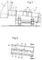
- FIG. 1 there is a bulk goods container at the outlet 1 connected to a pneumatic conveyor trough 2.
- a pneumatic conveyor trough 2 It is a well-known funding element, which as The bottom of a closed conveyor channel is an air-permeable one Has plate, which is from an air supply duct located below is pressurized with compressed air after the Passing the floor penetrates into the bed of material lying on it and placed it in a fluid state as a fluidized bed. Due to the slight gradient, it starts to move.
- the sieve device 4 To the pneumatic conveyor trough 2 is an elastic Compensator 3, the sieve device generally designated 4 connected, whose underflow by a pneumatic conveyor trough 5 is continued via an elastic compensator 6 is connected to the screening device. The overflow is discharged laterally at 7.
- the screening device 4 is on Supports 8 arranged by means of vibrating bearings 9 and with unbalance motors 10 equipped, which they according to known principles in Move vibration.
- FIG. 2 The structure of the screening device is shown in FIG. 2 one recognizes an upper sieve space 11, the bottom of which is flush the compensator 3 to the ventilation floor of the conveyor trough 2 connects. Underneath is a sieve sub-space 12 which as a pneumatic conveyor trough with a ventilation base 13 and a ventilation space 14 for the removal of the screen underflow is executed. At the pneumatic conveyor trough of this sieve sub-area is the pneumatic conveyor trough 5 via the compensator 6 connected in alignment.
- Ventilation floors 17 which compressed air from a line 18 with suitable actuators forth Ventilation rooms 19 can be supplied.
- These ventilation floors as well the ventilation floor of the conveyor trough 2 were with the top more general term fluid bed conveying surface.
- a chute 20 connects to the last screen surface 16, which removes the screen overflow and with flaps 21 is provided to the inflow and outflow of air if necessary prevent.
- Pendulum flap 22 may be provided.
- the material bed emerges from the pneumatic conveyor trough 2 in Condition of the fluidized bed in the sieve. Because of their fluidized state, the gradient and the vibration it runs largely over the first screen surface 16. This screen area is shorter than it is for completion the sieving process would be required. About the following Aeration path becomes the fluidization state of the Fluidized bed refreshed again so that it is fluidized Condition reached and overflows the following screen section, and immediately. The screen overflow is through chute 20 at the end discharged from the screening device.
Landscapes
- Engineering & Computer Science (AREA)
- Mechanical Engineering (AREA)
- Combined Means For Separation Of Solids (AREA)
- Processes Of Treating Macromolecular Substances (AREA)
- Automatic Analysis And Handling Materials Therefor (AREA)
- Excavating Of Shafts Or Tunnels (AREA)
- Devices And Processes Conducted In The Presence Of Fluids And Solid Particles (AREA)
Description
- Fig. 1
- die Seitenansicht eines Teils einer Anlage mit der erfindungsgemäßen Siebvorrichtung,
- Fig. 2
- einen Längsschnitt durch die Siebvorrichtung,
- Fig. 3
- eine Draufsicht auf die Siebvorrichtung und
- Fig. 4
- einen Querschnitt gemäß Linie IV-IV der Fig. 2.
Claims (5)
- Vorrichtung zum Sieben eines Schüttgutstroms, die einen Förderweg über eine Siebfläche hinweg bildet, dadurch gekennzeichnet, daß in dem Förderweg mindestens ein Belüftungsboden und mindestens eine Siebfläche (16) mit gleicher Förderrichtung hintereinander angeordnet sind.
- Vorrichtung nach Anspruch 1, dadurch gekennzeichnet, daß mehrere Belüftungsböden (17) und Siebflächen (16) hintereinander angeordnet sind.
- Vorrichtung nach Anspruch 1 oder 2, dadurch gekennzeichnet, daß die Siebfläche(n) (16) mit einem Vibrationsantrieb (10) verbunden ist (sind).
- Vorrichtung nach Anspruch 2 und 3, dadurch gekennzeichnet, daß der Belüftungsböden/die Belüftungsböden (17) und Siebfläche(n) (16) zu einer gemeinsam vibrierbaren Einheit zusammengefaßt sind.
- Vorrichtung nach einem der Ansprüche 1 bis 4, gekennzeichnet durch eine Einrichtung zur Erzeugung eines den Siebdurchgang fördernden Differenzdrucks.
Applications Claiming Priority (3)
| Application Number | Priority Date | Filing Date | Title |
|---|---|---|---|
| DE9307072U | 1993-05-10 | ||
| DE9307072U DE9307072U1 (de) | 1993-05-10 | 1993-05-10 | Vorrichtung zum Sieben eines Schüttgutstroms |
| PCT/EP1994/001504 WO1994026428A1 (de) | 1993-05-10 | 1994-05-10 | Verfahren und vorrichtung zum sieben eines schüttgutstroms |
Publications (2)
| Publication Number | Publication Date |
|---|---|
| EP0649349A1 EP0649349A1 (de) | 1995-04-26 |
| EP0649349B1 true EP0649349B1 (de) | 1998-04-22 |
Family
ID=6893088
Family Applications (1)
| Application Number | Title | Priority Date | Filing Date |
|---|---|---|---|
| EP94916946A Expired - Lifetime EP0649349B1 (de) | 1993-05-10 | 1994-05-10 | Verfahren und vorrichtung zum sieben eines schüttgutstroms |
Country Status (7)
| Country | Link |
|---|---|
| US (1) | US5586660A (de) |
| EP (1) | EP0649349B1 (de) |
| JP (1) | JPH07508932A (de) |
| AT (1) | ATE165258T1 (de) |
| DE (2) | DE9307072U1 (de) |
| ES (1) | ES2117274T3 (de) |
| WO (1) | WO1994026428A1 (de) |
Families Citing this family (6)
| Publication number | Priority date | Publication date | Assignee | Title |
|---|---|---|---|---|
| EP0855941B1 (de) * | 1995-10-19 | 2000-01-19 | OCRIM S.p.A. | Vorrichtung und apparat für die klassifizierung und trennung von teilchen im getreidemahlverfahren |
| US20050133465A1 (en) * | 2002-06-12 | 2005-06-23 | Derrick Corporation | Vibratory screen assembly and method of manufacture |
| US20030230541A1 (en) * | 2002-06-12 | 2003-12-18 | Derrick Mitchell J. | Vibratory screening machine with suction and pressure and method for screening a slurry |
| US20050082236A1 (en) * | 2002-06-12 | 2005-04-21 | Derrick Corporation | Vibratory screening machine with suction and method for screening a slurry |
| DE102008038645B4 (de) | 2008-08-12 | 2016-06-09 | Zeppelin Silos & Systems Gmbh | Grobgutseparator zum Trennen von Grobgut aus einem Schüttgut |
| CN117244778A (zh) * | 2023-09-27 | 2023-12-19 | 青海黄河上游水电开发有限责任公司 | 一种氧化铝输送结构 |
Family Cites Families (3)
| Publication number | Priority date | Publication date | Assignee | Title |
|---|---|---|---|---|
| US2200472A (en) * | 1938-06-29 | 1940-05-14 | Schering Corp | Granular material separating machine |
| GB671232A (en) * | 1949-07-05 | 1952-04-30 | Joanny Myard | Dust collecting plant |
| FR2087091A5 (de) * | 1970-05-05 | 1971-12-31 | Sosson Guy |
-
1993
- 1993-05-10 DE DE9307072U patent/DE9307072U1/de not_active Expired - Lifetime
-
1994
- 1994-05-10 EP EP94916946A patent/EP0649349B1/de not_active Expired - Lifetime
- 1994-05-10 US US08/360,794 patent/US5586660A/en not_active Expired - Fee Related
- 1994-05-10 JP JP6524951A patent/JPH07508932A/ja active Pending
- 1994-05-10 ES ES94916946T patent/ES2117274T3/es not_active Expired - Lifetime
- 1994-05-10 AT AT94916946T patent/ATE165258T1/de not_active IP Right Cessation
- 1994-05-10 WO PCT/EP1994/001504 patent/WO1994026428A1/de not_active Ceased
- 1994-05-10 DE DE59405776T patent/DE59405776D1/de not_active Expired - Fee Related
Also Published As
| Publication number | Publication date |
|---|---|
| WO1994026428A1 (de) | 1994-11-24 |
| ATE165258T1 (de) | 1998-05-15 |
| DE59405776D1 (de) | 1998-05-28 |
| US5586660A (en) | 1996-12-24 |
| EP0649349A1 (de) | 1995-04-26 |
| ES2117274T3 (es) | 1998-08-01 |
| DE9307072U1 (de) | 1994-09-22 |
| JPH07508932A (ja) | 1995-10-05 |
Similar Documents
| Publication | Publication Date | Title |
|---|---|---|
| EP0293426B1 (de) | Anlage und verfahren zur trockenen mahlvorbereitung von kornartigen nahrungs- und futtermitteln | |
| EP0182831B1 (de) | Vorrichtung und verfahren zum auslesen von schwergut, insbesondere steinen o.ä., aus getreide und anderen schüttgütern | |
| DE2851779A1 (de) | Streukopf | |
| AT393467B (de) | Schwingscheider | |
| DE69938137T2 (de) | Gerät zum klassieren von material | |
| DE2313847A1 (de) | Verfahren und vorrichtung zur abtrennung von sand von pflanzlichen materialien, insbesondere tabak | |
| DE69616922T2 (de) | Verfaren und Vorrichtung zum Aussortieren von schweren und leichten Materialteilchen | |
| EP0649349A1 (de) | Verfahren und vorrichtung zum sieben eines schüttgutstroms | |
| EP0332031B1 (de) | Zick-Zack-Sichter | |
| DE2837037C2 (de) | Drehtrommel-Luftstrom-Sortiervorrichtung zum Trennen von Feststoffgemischen wie Müll und dergleichen | |
| DE3038385A1 (de) | Verfahren und vorrichtung zum abtrennen von staubteilchen von mit diesen behafteten partikeln | |
| DE2641068A1 (de) | Steigrohrwindsichter zur entsandung von holzspaenen | |
| EP0391324B1 (de) | Schwingsortierer | |
| EP0427679B1 (de) | Einrichtung zum Fraktionieren von körnigem Gut | |
| DE946521C (de) | Luftsetzmaschine und Verfahren zur Aufbereitung von Feinkohle oder von aehnlichem Gut | |
| CH547667A (de) | Verfahren und vorrichtung zum anreichern durch sortieren und von angereicherten fraktionen koernigen gutes. | |
| DE19517850A1 (de) | Siebmaschine zur Vorsortierung von Materialmischungen | |
| DE1220597B (de) | Einrichtung zur Schuettung von Spanholz- od. dgl. -formlingen | |
| DE3833197C2 (de) | ||
| DE1458599B1 (de) | Vorrichtung zur Trennung von k¦rnigem Gut unterschiedlicher Dichte | |
| DE2922814A1 (de) | Streuvorrichtung zum herstellen eines spaenevlieses, das zu spanplatten verpressbar ist | |
| DE8812372U1 (de) | Zweistufiger Schwingsortierer | |
| DE20005076U1 (de) | Anlage zur selektiven Trennung eines Gemischmassenstroms | |
| DE2432179A1 (de) | Verfahren und vorrichtung zum kontinuierlichen absieben von mikrokoernungen | |
| DE1280270B (de) | Profilfreie Maschine zum Reinigen des Eisenbahnbettungsschotters |
Legal Events
| Date | Code | Title | Description |
|---|---|---|---|
| PUAI | Public reference made under article 153(3) epc to a published international application that has entered the european phase |
Free format text: ORIGINAL CODE: 0009012 |
|
| 17P | Request for examination filed |
Effective date: 19941219 |
|
| AK | Designated contracting states |
Kind code of ref document: A1 Designated state(s): AT DE DK ES FR GB IT |
|
| 17Q | First examination report despatched |
Effective date: 19970327 |
|
| GRAG | Despatch of communication of intention to grant |
Free format text: ORIGINAL CODE: EPIDOS AGRA |
|
| GRAG | Despatch of communication of intention to grant |
Free format text: ORIGINAL CODE: EPIDOS AGRA |
|
| GRAH | Despatch of communication of intention to grant a patent |
Free format text: ORIGINAL CODE: EPIDOS IGRA |
|
| GRAH | Despatch of communication of intention to grant a patent |
Free format text: ORIGINAL CODE: EPIDOS IGRA |
|
| RAP1 | Party data changed (applicant data changed or rights of an application transferred) |
Owner name: BMH CLAUDIUS PETERS AG |
|
| GRAA | (expected) grant |
Free format text: ORIGINAL CODE: 0009210 |
|
| AK | Designated contracting states |
Kind code of ref document: B1 Designated state(s): AT DE DK ES FR GB IT |
|
| REF | Corresponds to: |
Ref document number: 165258 Country of ref document: AT Date of ref document: 19980515 Kind code of ref document: T |
|
| REF | Corresponds to: |
Ref document number: 59405776 Country of ref document: DE Date of ref document: 19980528 |
|
| ITF | It: translation for a ep patent filed | ||
| PG25 | Lapsed in a contracting state [announced via postgrant information from national office to epo] |
Ref country code: DK Free format text: LAPSE BECAUSE OF FAILURE TO SUBMIT A TRANSLATION OF THE DESCRIPTION OR TO PAY THE FEE WITHIN THE PRESCRIBED TIME-LIMIT Effective date: 19980722 |
|
| REG | Reference to a national code |
Ref country code: ES Ref legal event code: FG2A Ref document number: 2117274 Country of ref document: ES Kind code of ref document: T3 |
|
| GBT | Gb: translation of ep patent filed (gb section 77(6)(a)/1977) |
Effective date: 19980722 |
|
| ET | Fr: translation filed | ||
| REG | Reference to a national code |
Ref country code: FR Ref legal event code: CL |
|
| PLBE | No opposition filed within time limit |
Free format text: ORIGINAL CODE: 0009261 |
|
| STAA | Information on the status of an ep patent application or granted ep patent |
Free format text: STATUS: NO OPPOSITION FILED WITHIN TIME LIMIT |
|
| 26N | No opposition filed | ||
| PGFP | Annual fee paid to national office [announced via postgrant information from national office to epo] |
Ref country code: DE Payment date: 20010723 Year of fee payment: 8 |
|
| REG | Reference to a national code |
Ref country code: GB Ref legal event code: IF02 |
|
| PGFP | Annual fee paid to national office [announced via postgrant information from national office to epo] |
Ref country code: GB Payment date: 20020416 Year of fee payment: 9 |
|
| PGFP | Annual fee paid to national office [announced via postgrant information from national office to epo] |
Ref country code: FR Payment date: 20020517 Year of fee payment: 9 Ref country code: ES Payment date: 20020517 Year of fee payment: 9 |
|
| PGFP | Annual fee paid to national office [announced via postgrant information from national office to epo] |
Ref country code: AT Payment date: 20020523 Year of fee payment: 9 |
|
| PG25 | Lapsed in a contracting state [announced via postgrant information from national office to epo] |
Ref country code: DE Free format text: LAPSE BECAUSE OF NON-PAYMENT OF DUE FEES Effective date: 20021203 |
|
| PG25 | Lapsed in a contracting state [announced via postgrant information from national office to epo] |
Ref country code: GB Free format text: LAPSE BECAUSE OF NON-PAYMENT OF DUE FEES Effective date: 20030510 Ref country code: AT Free format text: LAPSE BECAUSE OF NON-PAYMENT OF DUE FEES Effective date: 20030510 |
|
| PG25 | Lapsed in a contracting state [announced via postgrant information from national office to epo] |
Ref country code: ES Free format text: LAPSE BECAUSE OF NON-PAYMENT OF DUE FEES Effective date: 20030512 |
|
| GBPC | Gb: european patent ceased through non-payment of renewal fee |
Effective date: 20030510 |
|
| PG25 | Lapsed in a contracting state [announced via postgrant information from national office to epo] |
Ref country code: FR Free format text: LAPSE BECAUSE OF NON-PAYMENT OF DUE FEES Effective date: 20040130 |
|
| REG | Reference to a national code |
Ref country code: FR Ref legal event code: ST |
|
| REG | Reference to a national code |
Ref country code: ES Ref legal event code: FD2A Effective date: 20030512 |
|
| PG25 | Lapsed in a contracting state [announced via postgrant information from national office to epo] |
Ref country code: IT Free format text: LAPSE BECAUSE OF NON-PAYMENT OF DUE FEES;WARNING: LAPSES OF ITALIAN PATENTS WITH EFFECTIVE DATE BEFORE 2007 MAY HAVE OCCURRED AT ANY TIME BEFORE 2007. THE CORRECT EFFECTIVE DATE MAY BE DIFFERENT FROM THE ONE RECORDED. Effective date: 20050510 |