EP0648614A1 - Wärmeübertragungsbild aufnehmendes Blatt - Google Patents
Wärmeübertragungsbild aufnehmendes Blatt Download PDFInfo
- Publication number
- EP0648614A1 EP0648614A1 EP19940115018 EP94115018A EP0648614A1 EP 0648614 A1 EP0648614 A1 EP 0648614A1 EP 19940115018 EP19940115018 EP 19940115018 EP 94115018 A EP94115018 A EP 94115018A EP 0648614 A1 EP0648614 A1 EP 0648614A1
- Authority
- EP
- European Patent Office
- Prior art keywords
- dye
- thermal transfer
- receiving sheet
- transfer image
- layer
- Prior art date
- Legal status (The legal status is an assumption and is not a legal conclusion. Google has not performed a legal analysis and makes no representation as to the accuracy of the status listed.)
- Granted
Links
Images
Classifications
-
- B—PERFORMING OPERATIONS; TRANSPORTING
- B41—PRINTING; LINING MACHINES; TYPEWRITERS; STAMPS
- B41M—PRINTING, DUPLICATING, MARKING, OR COPYING PROCESSES; COLOUR PRINTING
- B41M5/00—Duplicating or marking methods; Sheet materials for use therein
- B41M5/26—Thermography ; Marking by high energetic means, e.g. laser otherwise than by burning, and characterised by the material used
- B41M5/40—Thermography ; Marking by high energetic means, e.g. laser otherwise than by burning, and characterised by the material used characterised by the base backcoat, intermediate, or covering layers, e.g. for thermal transfer dye-donor or dye-receiver sheets; Heat, radiation filtering or absorbing means or layers; combined with other image registration layers or compositions; Special originals for reproduction by thermography
- B41M5/42—Intermediate, backcoat, or covering layers
- B41M5/44—Intermediate, backcoat, or covering layers characterised by the macromolecular compounds
- B41M5/443—Silicon-containing polymers, e.g. silicones, siloxanes
-
- B—PERFORMING OPERATIONS; TRANSPORTING
- B41—PRINTING; LINING MACHINES; TYPEWRITERS; STAMPS
- B41M—PRINTING, DUPLICATING, MARKING, OR COPYING PROCESSES; COLOUR PRINTING
- B41M5/00—Duplicating or marking methods; Sheet materials for use therein
- B41M5/50—Recording sheets characterised by the coating used to improve ink, dye or pigment receptivity, e.g. for ink-jet or thermal dye transfer recording
- B41M5/52—Macromolecular coatings
-
- B—PERFORMING OPERATIONS; TRANSPORTING
- B41—PRINTING; LINING MACHINES; TYPEWRITERS; STAMPS
- B41M—PRINTING, DUPLICATING, MARKING, OR COPYING PROCESSES; COLOUR PRINTING
- B41M2205/00—Printing methods or features related to printing methods; Location or type of the layers
- B41M2205/32—Thermal receivers
-
- B—PERFORMING OPERATIONS; TRANSPORTING
- B41—PRINTING; LINING MACHINES; TYPEWRITERS; STAMPS
- B41M—PRINTING, DUPLICATING, MARKING, OR COPYING PROCESSES; COLOUR PRINTING
- B41M5/00—Duplicating or marking methods; Sheet materials for use therein
- B41M5/26—Thermography ; Marking by high energetic means, e.g. laser otherwise than by burning, and characterised by the material used
- B41M5/40—Thermography ; Marking by high energetic means, e.g. laser otherwise than by burning, and characterised by the material used characterised by the base backcoat, intermediate, or covering layers, e.g. for thermal transfer dye-donor or dye-receiver sheets; Heat, radiation filtering or absorbing means or layers; combined with other image registration layers or compositions; Special originals for reproduction by thermography
- B41M5/42—Intermediate, backcoat, or covering layers
- B41M5/423—Intermediate, backcoat, or covering layers characterised by non-macromolecular compounds, e.g. waxes
-
- B—PERFORMING OPERATIONS; TRANSPORTING
- B41—PRINTING; LINING MACHINES; TYPEWRITERS; STAMPS
- B41M—PRINTING, DUPLICATING, MARKING, OR COPYING PROCESSES; COLOUR PRINTING
- B41M5/00—Duplicating or marking methods; Sheet materials for use therein
- B41M5/26—Thermography ; Marking by high energetic means, e.g. laser otherwise than by burning, and characterised by the material used
- B41M5/40—Thermography ; Marking by high energetic means, e.g. laser otherwise than by burning, and characterised by the material used characterised by the base backcoat, intermediate, or covering layers, e.g. for thermal transfer dye-donor or dye-receiver sheets; Heat, radiation filtering or absorbing means or layers; combined with other image registration layers or compositions; Special originals for reproduction by thermography
- B41M5/42—Intermediate, backcoat, or covering layers
- B41M5/426—Intermediate, backcoat, or covering layers characterised by inorganic compounds, e.g. metals, metal salts, metal complexes
-
- B—PERFORMING OPERATIONS; TRANSPORTING
- B41—PRINTING; LINING MACHINES; TYPEWRITERS; STAMPS
- B41M—PRINTING, DUPLICATING, MARKING, OR COPYING PROCESSES; COLOUR PRINTING
- B41M5/00—Duplicating or marking methods; Sheet materials for use therein
- B41M5/26—Thermography ; Marking by high energetic means, e.g. laser otherwise than by burning, and characterised by the material used
- B41M5/40—Thermography ; Marking by high energetic means, e.g. laser otherwise than by burning, and characterised by the material used characterised by the base backcoat, intermediate, or covering layers, e.g. for thermal transfer dye-donor or dye-receiver sheets; Heat, radiation filtering or absorbing means or layers; combined with other image registration layers or compositions; Special originals for reproduction by thermography
- B41M5/42—Intermediate, backcoat, or covering layers
- B41M5/44—Intermediate, backcoat, or covering layers characterised by the macromolecular compounds
-
- B—PERFORMING OPERATIONS; TRANSPORTING
- B41—PRINTING; LINING MACHINES; TYPEWRITERS; STAMPS
- B41M—PRINTING, DUPLICATING, MARKING, OR COPYING PROCESSES; COLOUR PRINTING
- B41M5/00—Duplicating or marking methods; Sheet materials for use therein
- B41M5/50—Recording sheets characterised by the coating used to improve ink, dye or pigment receptivity, e.g. for ink-jet or thermal dye transfer recording
- B41M5/52—Macromolecular coatings
- B41M5/5218—Macromolecular coatings characterised by inorganic additives, e.g. pigments, clays
-
- B—PERFORMING OPERATIONS; TRANSPORTING
- B41—PRINTING; LINING MACHINES; TYPEWRITERS; STAMPS
- B41M—PRINTING, DUPLICATING, MARKING, OR COPYING PROCESSES; COLOUR PRINTING
- B41M5/00—Duplicating or marking methods; Sheet materials for use therein
- B41M5/50—Recording sheets characterised by the coating used to improve ink, dye or pigment receptivity, e.g. for ink-jet or thermal dye transfer recording
- B41M5/52—Macromolecular coatings
- B41M5/529—Macromolecular coatings characterised by the use of fluorine- or silicon-containing organic compounds
-
- Y—GENERAL TAGGING OF NEW TECHNOLOGICAL DEVELOPMENTS; GENERAL TAGGING OF CROSS-SECTIONAL TECHNOLOGIES SPANNING OVER SEVERAL SECTIONS OF THE IPC; TECHNICAL SUBJECTS COVERED BY FORMER USPC CROSS-REFERENCE ART COLLECTIONS [XRACs] AND DIGESTS
- Y10—TECHNICAL SUBJECTS COVERED BY FORMER USPC
- Y10S—TECHNICAL SUBJECTS COVERED BY FORMER USPC CROSS-REFERENCE ART COLLECTIONS [XRACs] AND DIGESTS
- Y10S428/00—Stock material or miscellaneous articles
- Y10S428/913—Material designed to be responsive to temperature, light, moisture
-
- Y—GENERAL TAGGING OF NEW TECHNOLOGICAL DEVELOPMENTS; GENERAL TAGGING OF CROSS-SECTIONAL TECHNOLOGIES SPANNING OVER SEVERAL SECTIONS OF THE IPC; TECHNICAL SUBJECTS COVERED BY FORMER USPC CROSS-REFERENCE ART COLLECTIONS [XRACs] AND DIGESTS
- Y10—TECHNICAL SUBJECTS COVERED BY FORMER USPC
- Y10S—TECHNICAL SUBJECTS COVERED BY FORMER USPC CROSS-REFERENCE ART COLLECTIONS [XRACs] AND DIGESTS
- Y10S428/00—Stock material or miscellaneous articles
- Y10S428/914—Transfer or decalcomania
-
- Y—GENERAL TAGGING OF NEW TECHNOLOGICAL DEVELOPMENTS; GENERAL TAGGING OF CROSS-SECTIONAL TECHNOLOGIES SPANNING OVER SEVERAL SECTIONS OF THE IPC; TECHNICAL SUBJECTS COVERED BY FORMER USPC CROSS-REFERENCE ART COLLECTIONS [XRACs] AND DIGESTS
- Y10—TECHNICAL SUBJECTS COVERED BY FORMER USPC
- Y10T—TECHNICAL SUBJECTS COVERED BY FORMER US CLASSIFICATION
- Y10T428/00—Stock material or miscellaneous articles
- Y10T428/24—Structurally defined web or sheet [e.g., overall dimension, etc.]
- Y10T428/24802—Discontinuous or differential coating, impregnation or bond [e.g., artwork, printing, retouched photograph, etc.]
- Y10T428/24893—Discontinuous or differential coating, impregnation or bond [e.g., artwork, printing, retouched photograph, etc.] including particulate material
-
- Y—GENERAL TAGGING OF NEW TECHNOLOGICAL DEVELOPMENTS; GENERAL TAGGING OF CROSS-SECTIONAL TECHNOLOGIES SPANNING OVER SEVERAL SECTIONS OF THE IPC; TECHNICAL SUBJECTS COVERED BY FORMER USPC CROSS-REFERENCE ART COLLECTIONS [XRACs] AND DIGESTS
- Y10—TECHNICAL SUBJECTS COVERED BY FORMER USPC
- Y10T—TECHNICAL SUBJECTS COVERED BY FORMER US CLASSIFICATION
- Y10T428/00—Stock material or miscellaneous articles
- Y10T428/25—Web or sheet containing structurally defined element or component and including a second component containing structurally defined particles
- Y10T428/254—Polymeric or resinous material
-
- Y—GENERAL TAGGING OF NEW TECHNOLOGICAL DEVELOPMENTS; GENERAL TAGGING OF CROSS-SECTIONAL TECHNOLOGIES SPANNING OVER SEVERAL SECTIONS OF THE IPC; TECHNICAL SUBJECTS COVERED BY FORMER USPC CROSS-REFERENCE ART COLLECTIONS [XRACs] AND DIGESTS
- Y10—TECHNICAL SUBJECTS COVERED BY FORMER USPC
- Y10T—TECHNICAL SUBJECTS COVERED BY FORMER US CLASSIFICATION
- Y10T428/00—Stock material or miscellaneous articles
- Y10T428/31504—Composite [nonstructural laminate]
- Y10T428/31507—Of polycarbonate
-
- Y—GENERAL TAGGING OF NEW TECHNOLOGICAL DEVELOPMENTS; GENERAL TAGGING OF CROSS-SECTIONAL TECHNOLOGIES SPANNING OVER SEVERAL SECTIONS OF THE IPC; TECHNICAL SUBJECTS COVERED BY FORMER USPC CROSS-REFERENCE ART COLLECTIONS [XRACs] AND DIGESTS
- Y10—TECHNICAL SUBJECTS COVERED BY FORMER USPC
- Y10T—TECHNICAL SUBJECTS COVERED BY FORMER US CLASSIFICATION
- Y10T428/00—Stock material or miscellaneous articles
- Y10T428/31504—Composite [nonstructural laminate]
- Y10T428/31551—Of polyamidoester [polyurethane, polyisocyanate, polycarbamate, etc.]
-
- Y—GENERAL TAGGING OF NEW TECHNOLOGICAL DEVELOPMENTS; GENERAL TAGGING OF CROSS-SECTIONAL TECHNOLOGIES SPANNING OVER SEVERAL SECTIONS OF THE IPC; TECHNICAL SUBJECTS COVERED BY FORMER USPC CROSS-REFERENCE ART COLLECTIONS [XRACs] AND DIGESTS
- Y10—TECHNICAL SUBJECTS COVERED BY FORMER USPC
- Y10T—TECHNICAL SUBJECTS COVERED BY FORMER US CLASSIFICATION
- Y10T428/00—Stock material or miscellaneous articles
- Y10T428/31504—Composite [nonstructural laminate]
- Y10T428/31652—Of asbestos
- Y10T428/31663—As siloxane, silicone or silane
-
- Y—GENERAL TAGGING OF NEW TECHNOLOGICAL DEVELOPMENTS; GENERAL TAGGING OF CROSS-SECTIONAL TECHNOLOGIES SPANNING OVER SEVERAL SECTIONS OF THE IPC; TECHNICAL SUBJECTS COVERED BY FORMER USPC CROSS-REFERENCE ART COLLECTIONS [XRACs] AND DIGESTS
- Y10—TECHNICAL SUBJECTS COVERED BY FORMER USPC
- Y10T—TECHNICAL SUBJECTS COVERED BY FORMER US CLASSIFICATION
- Y10T428/00—Stock material or miscellaneous articles
- Y10T428/31504—Composite [nonstructural laminate]
- Y10T428/31801—Of wax or waxy material
-
- Y—GENERAL TAGGING OF NEW TECHNOLOGICAL DEVELOPMENTS; GENERAL TAGGING OF CROSS-SECTIONAL TECHNOLOGIES SPANNING OVER SEVERAL SECTIONS OF THE IPC; TECHNICAL SUBJECTS COVERED BY FORMER USPC CROSS-REFERENCE ART COLLECTIONS [XRACs] AND DIGESTS
- Y10—TECHNICAL SUBJECTS COVERED BY FORMER USPC
- Y10T—TECHNICAL SUBJECTS COVERED BY FORMER US CLASSIFICATION
- Y10T428/00—Stock material or miscellaneous articles
- Y10T428/31504—Composite [nonstructural laminate]
- Y10T428/31855—Of addition polymer from unsaturated monomers
Definitions
- the present invention relates to a thermal transfer image-receiving sheet which is receptive to a dye transferred from a thermal transfer sheet by heating, which thermal transfer image-receiving sheet can be widely utilized in the field of various color printers including video printers.
- a system which has attracted attention is such that a sublimable dye as a recording material is put on an image-receiving sheet and heated by means of a thermal head in response to recording signals to transfer the dye onto the image-receiving sheet, thereby forming a recorded image.
- the sharpness is very high and, at the same time, the transparency is excellent, so that it is possible to provide an image having excellent reproduction and gradation of intermediate colors equivalent to those of an image formed by the conventional full color offset printing and gravure printing.
- the formed image has a high quality comparable to photographic images.
- Printers in current use in the above thermal transfer system are mainly of such a type that a thermal transfer image-receiving sheet is automatically carried to a thermal transfer section within a printer and, after printing, automatically delivered from the printer. Further, in order to carry out overlap printing of three colors or four colors, it is a common practice to provide a detection mark on the thermal transfer image-receiving sheet in its image-unreceptive surface, that is, the back surface, located opposite to the image-receiving surface for the purpose of preventing the occurrence of a shear in the printing position of each color.
- the construction of the thermal transfer sheet but also the construction of the image-receiving sheet on which an image is to be formed is important to the practice of the above thermal transfer method with a high efficiency.
- the properties of the image-unreceptive surface (back surface) located opposite to the image-receptive surface of the thermal transfer image-receiving sheet are important for smoothly carrying out automatic feed and delivery of the thermal transfer image-receiving sheet.
- the dye on the print surface migrates to the back surface of another thermal transfer image-receiving sheet in contact with the print surface to remarkably stain the back surface, which deteriorates the appearance. Further, in this case, the color of the print surface is partly or entirely dropped out, or restaining occur.
- a back surface free from a detection mark as in photographic paper is preferred from the viewpoint of appearance.
- a dye-receptive layer on both surfaces of the substrate sheet is considered as a means for solving the problem of heat fusing of the back surface.
- the dye migrates to cause problems of a lowering in image density, staining of contact surface, restaining and the like.
- the dye-receptive layer comprises a dyeable resin and is even, the image-receptive layers are likely to come into close contact with each other, which, also in the stage before printing, results in a problem of a failure in automatic feed such as a problem that a plurality of image-receiving sheets are carried together in an overlapped state in a feeder of a printer.
- a filler is added to the image-receptive layer for the purpose of preventing the occurrence of this problem, the highlight portion of the print is likely to become unsharp.
- Another means for solving the above problem is to add a release agent to the back surface layer as a dye-unreceptive layer.
- the release agent is added in an amount sufficient to impart satisfactory releasability, the releasing component contained in the back surface layer is transferred to the image-receptive surface when the back surface layer is put on top of the image-receptive surface, which unfavorably raises problems of occurrence of a failure in printing such as partial dropout in the print portion and uneven print density, a lowering in coefficient of dynamic friction between the image-receptive surface of the image-receiving sheet and the transfer agent surface of the thermal transfer sheet, which is causative of the occurrence of a shear in the printing position of each color.
- the releasing component contained in the back surface layer migrates to a feed and delivery mechanism, such as a paper feed rubber roller, and a platen rubber roller in a printer, which gives rise to a change in coefficient of friction of these members, so that troubles are likely to occur such as a failure in feed and delivery of sheets and oblique carrying of the image-receiving sheet.
- a feed and delivery mechanism such as a paper feed rubber roller, and a platen rubber roller in a printer
- an object of the present invention is to solve the above problems of the prior art and to provide a thermal transfer image-receiving sheet having excellent service properties for use in a thermal transfer system where a sublimable dye is used, which thermal transfer image-receiving sheet hardly causes a lowering in print density and migration of dye to the back surface of the image-receiving sheet when a plurality of image-receiving sheets are put on top of another for storage, can be delivered from the printer without fusing to the thermal transfer sheet by virtue of excellent releasability of the back surface even though printing is carried out on the thermal transfer image-receiving sheet with the image-receiving surface and the back surface being inversive and is free from an adverse effect of the release agent added to the back surface layer on the image-receiving surface and substantially free from the migration of the release agent to a sheet feed and delivery mechanism and a platen rubber roller.
- the present inventors have made extensive and intensive studies with a view to solving the above problems, which has led to the completion of the present invention.
- a thermal transfer image-receiving sheet comprising a substrate sheet, a dye-receptive layer provided on one surface of said substrate sheet and a dye-unreceptive layer provided on the other surface of said substrate sheet, the dye-unreceptive layer comprising a composition composed mainly of at least one thermoplastic resin having at least one reactive functional group and an isocyanate compound or a chelate compound.
- a thermal transfer image-receiving sheet comprising a substrate sheet, a dye-receptive layer provided on one surface of said substrate sheet and a dye-unreceptive layer provided on the other surface of said substrate sheet, said dye-unreceptive layer comprising at least one release agent at least one of which is the same as that contained in said dye-receptive layer.
- a thermal transfer image-receiving sheet comprising a substrate sheet, a dye-receptive layer provided on one surface of said substrate sheet and a dye-unreceptive layer provided on the other surface of said substrate sheet, said dye-unreceptive layer comprising at least one release agent at least one of which does not migrate to said dye-receptive layer.
- a thermal transfer image-receiving sheet comprising a substrate sheet, a dye-receptive layer provided on one surface of said substrate sheet and a dye-unreceptive layer provided on the other surface of said substrate sheet, said dye-unreceptive layer comprising at least one release agent at least one of which comprises a cured product obtained by a reaction of a reactive silicone oil.
- a thermal transfer image-receiving sheet comprising a substrate sheet, a dye-receptive layer provided on one surface of said substrate sheet and a dye-unreceptive layer provided on the other surface of said substrate sheet, said dye-unreceptive layer comprising at least one release agent at least one of which comprises wax.
- a thermal transfer image-receiving sheet comprising a substrate sheet, a dye-receptive layer provided on one surface of said substrate sheet and a lubricious back surface layer provided on the other surface of said substrate sheet, said lubricious back surface layer comprising a binder and a nylon filler.
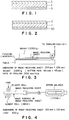
- FIG. 1 A typical cross-sectional view of an embodiment of the thermal transfer image-receiving sheet according to the first aspect of the present invention is shown in Fig. 1.
- This thermal transfer image-receiving sheet comprises a substrate sheet 1, a dye-receptive layer 2 provided on one surface of the substrate sheet and a dye-unreceptive layer 3 as a back surface provided on the other surface of the substrate sheet, characterized in that the dye-unreceptive layer 3 comprises a composition composed mainly of at least one thermoplastic resin having at least one reactive functional group and an isocyanate compound or a chelate compound.
- materials usable in the substrate sheet include papers. Any of various papers per se, converted papers and other types of papers may be used, and examples thereof include wood free paper, coated paper, art paper, cast coated paper and fiber board and other types of papers such as paper impregnated with an resin emulsion, a synthetic rubber latex or the like and paper containing an internally added synthetic resin. Further, a laminated paper comprising the above paper and various plastic films may also be used.
- plastic film examples include a polyolefin resin film, a hard polyvinyl chloride film, a polyester resin film, a polystyrene film, a polycarbonate film, a polyacrylonitrile film and a polymethacrylate film.
- plastic films are not particularly limited, and use may be made of not only transparent films but also a white opaque film or an expanded film prepared by adding a white pigment or filler to the above synthetic resin and forming a film from the mixture or expanding the mixture.
- the above materials may be used alone. Alternatively, as described above in connection with paper, they may be used as a laminate comprising a combination thereof with other materials. Further, in the formation of a dye-receptive layer or a dye-unreceptive layer (a back surface layer) on the above substrate sheet, it is also possible to conduct a corona discharge treatment or provide a primer coating or an intermediate layer according to need.
- the thickness of the substrate sheet is in the range of from about 10 ⁇ m to 400 ⁇ m, preferably in the range of from 100 to 300 ⁇ m.
- the dye-receptive layer is not particularly limited and may be any known dye-receptive layer commonly used in the sublimation thermal dye transfer system.
- the following materials may be used.
- mixtures or copolymers thereof may also be used.
- the dye-receptive layer is brought in contact with a thermal transfer sheet, and the laminate is pressed with heating by means of a thermal head or the like, so that the dye-receptive layer is likely to stick to the surface of the thermal transfer sheet.
- a releasing agent permeable to a dye is generally incorporated into the above resin.
- Solid waxes, fluorine or phosphoric ester surfactants, silicone oils may be used as the release agent.
- silicone oils may be in an oil form, reaction-curable silicone oils are preferred.
- a combination of an amino-modified silicone with an epoxy-modified silicone is preferred.
- the amount of the release agent added is 5 to 50% by weight, preferably 10 to 20% by weight, based on the weight of the resin when the release agent is solid wax, and 0.5 to 10% by weight based on the resin when the release agent is a fluorine or phosphoric ester surfactant.
- the curable silicone oils may be used in a large amount because they are not sticky, and the amount of the curable silicone oils added may be in the range of from 0.5 to 30% by weight based on the amount of the resin. In all the above release agents, when the amount is excessively small, the releasing effect becomes unsatisfactory. On the other hand, when the amount is excessive, the receptivity to a dye is lowered, so that insufficient recording density and other adverse effects occur.
- the dye-receptive layer may contain inorganic fillers such as finely divided silica.
- the dye-receptive layer is formed by dissolving or dispersing the above-described materials for constituting the dye-receptive layer in a solvent to prepare a coating solution, coating the coating solution by gravure reverse coating or other coating methods and drying the resultant coating.
- the coverage may be in the range of from 1.5 to 15 g/m2, preferably in the range of from 1.5 to 6.0 g/m2.
- the thermal transfer image-receiving sheet according to the present invention is characterized by the dye-unreceptive layer (back surface layer).
- the thermal transfer image-receiving sheet causes no staining of the back surface layer with a dye even when a plurality of image-receiving sheets after printing are put on top of one another for storage, has an excellent suitability for automatic feeding and can be delivered from the printer without fusing to a thermal transfer sheet by virtue of excellent releasability of the back surface even though it is fed into the printer with the back surface and the image-receiving surface being inversive.
- the dye-unreceptive layer comprises a composition composed mainly of at least one thermoplastic resin having at least one reactive functional group, preferably at least one vinyl resin having a hydroxyl group and an isocyanate compound or a chelate compound. If necessary, it may further comprise any one or both of an organic and/or inorganic filler and a release agent.
- thermoplastic resins may also be added for the purpose of improving the productivity and gloss in such an amount as will not be detrimental to the performance of the dye-unreceptive layer.
- the regulation of the hydroxyl value in the vinyl resin is easier than that in polyester resins, polyolefin resins and polycarbonate resins and other resins, so that the degree of crosslinking can be easily controlled as desired, which enables the above-mentioned staining of the back surface caused by the migration of the dye to be easily prevented.
- the vinyl resin wherein the hydroxyl value can be easily regulated is preferred by taking into consideration easy optimization of the solubility in the solvent used, the pot life of the isocyanate compound or chelate compound, which is generally unstable against water, and the like.
- the vinyl resin examples include polyvinyl alcohol resin, polyvinyl formal resin, polyvinyl acetoacetal resin, polyvinyl butyral resin and vinyl chloride/vinyl acetate/polyvinyl alcohol copolymer resin.
- High Tg and hydrophilicity are desired from the viewpoint of resistance to staining with a dye, and the regulation of solubility in general-purpose solvents and viscosity are required from the viewpoint of production stability. For this reason, the polyvinyl butyral resin is particularly preferred.
- thermoplastic resin used in the present invention examples include vinyl resins, such as polyvinyl alcohol resins, polyvinyl acetate resins, polyvinyl chloride resins, vinyl chloride/vinyl acetate copolymer resins, acrylic resins, polystyrene resins, polyvinyl formal resins, polyvinyl acetoacetal resins and polyvinyl butyral resins, cellulosic resins, polyester resins and polyolefin resins.
- vinyl resins such as polyvinyl alcohol resins, polyvinyl acetate resins, polyvinyl chloride resins, vinyl chloride/vinyl acetate copolymer resins, acrylic resins, polystyrene resins, polyvinyl formal resins, polyvinyl acetoacetal resins and polyvinyl butyral resins, cellulosic resins, polyester resins and polyolefin resins.
- the isocyanate compound may be any of an aromatic isocyanate and an aliphatic isocyanate, and the amount of the isocyanate compound added is preferably equal to or twice the amount of the reactive functional group of the thermoplastic resin having a reactive functional group.
- the chelate compound may be a titanium chelate compound, a zirconium chelate compound, an aluminum chelate compound or the like. Chelate compounds having a high curing activity are preferred.
- the amount of the chelate compound added is 25 to 300 parts by weight based on 100 parts by weight of the thermoplastic resin having a reactive functional group.
- Fillers used in the present invention are not particularly limited, and examples thereof include polyethylene wax, bisamides, polyamides, such as nylon, acrylic resins, crosslinked polystyrene, silicone resins, silicone rubbers, talc, calcium carbonate and titanium oxide. Fillers capable of improving the lubricity are preferred, and the particle diameter is suitably in the range of from 2 to 15 ⁇ m.
- nylon 12 filler is particularly preferred from the viewpoint of resistance to offset of dye, that is, staining resistance, and good lubricity.
- the amount of the filler added may be in the range of from 0 to 200 parts by weight based on 100 parts by weight in total of the thermoplastic resin and the release agent.
- various surfactants, silicon compounds, fluorine compounds and other compounds may be used as the release agent.
- silicon compounds are preferred.
- Three-dimensional crosslinked silicones and reactive silicone oils are preferred from the viewpoint of avoiding the migration to other places.
- the reactive silicone oil is particularly preferred because the use thereof in a small amount can provide a sufficient releasability and there is no fear of the release agent migrating to other places.
- the silicone oil may be added in an oil form to the resin for constituting the dye-unreceptive layer, coated in a sufficiently dispersed state, dried and then crosslinked. Further, when the reactive silicone oil reacts with an isocyanate compound or a chelate compound as the curing agent for the thermoplastic resin, thereby causing the reactive silicone oil to be fixed to the resin, the fear of the migration can be completely eliminated.
- the reactive silicone include an amino-modified silicone and an epoxy-modified silicone and a cured product obtained by a reaction thereof, an addition-polymerizable silicone and a cured product obtained by a reaction thereof, and a radiation-curable silicone and a cured product obtained by a reaction thereof.
- Further preferred examples of the reactive silicone include a hydroxyl-modified silicone oil and a carboxyl-modified silicone oil having an active hydrogen which can be cured when used in combination with an isocyanate compound or a chelate compound.
- the amount of the release agent added is suitably in the range of from 0 to 5 parts by weight based on 100 parts by weight of the thermoplastic resin.
- wire bar coating was used for the formation of the dye-unreceptive layer (back surface layer) by coating from the viewpoint of convenience.
- the coating method is not particularly limited and may be freely selected from gravure coating, roll coating, blade coating, knife coating, spray coating and other conventional coating methods.
- the thermal transfer image-receiving sheet according to the present invention comprises a substrate sheet, a dye-receptive layer provided on one surface of said substrate sheet and a dye-unreceptive layer provided on the other surface of said substrate sheet, the dye-unreceptive layer comprising a composition composed mainly of at least one thermoplastic resin having at least one reactive functional group, preferably a vinyl resin having a hydroxyl group, and an isocyanate compound or a chelate compound.
- the adoption of such a constitution brings the thermoplastic resin of the dye-unreceptive layer as a back surface layer of the image-receiving sheet to a crosslinked structure, which contributes to an improvement in heat resistance.
- the sublimable dye receptivity of the dye-unreceptive layer in the image-receiving sheet can also be lowered, so that the stain of the back surface with a sublimable dye can be reduced even when a plurality of sheets are stored with the surface of the print facing the back surface.
- the thermoplastic resin of the dye-unreceptive layer as the back surface may be a thermoplastic resin having a hydroxyl group as the reactive functional group, more specifically, polyvinyl formal, polyvinyl acetoacetal or polyvinyl butyral.
- This embodiment enables the thermoplastic resin to be more surely reacted, so that the above effect can be attained more efficiently and stably.
- the dye-unreceptive layer provided in the back surface may further comprise an organic filler and/or an inorganic filler or a release agent, or an organic filler and/or an inorganic filler and a release agent.
- the above effect can be further improved. Specifically, curing of the binder resin contributes to an improvement in heat resistance, and the addition of the release agent in the minimum required amount contributes to a further improvement in releasability and lubricity of the back surface of the thermal transfer image-receiving sheet. Further, since the release agent is fixed to the dye-unreceptive layer, it is not transferred to other places.
- the automatic feed and delivery of the image-receiving sheet in a printer becomes more smooth. Furthermore, even though the thermal transfer sheet is fed into a printer with the back surface and the image-receiving surface of the image-receiving sheet being inversive and, in this state, printing is carried out, the sheet can be successfully delivered from the printer without the occurrence of heat fusing or sticking between the thermal transfer sheet and the back surface of the image-receiving sheet.
- FIG. 1 A typical cross-sectional view of an embodiment of the thermal transfer image-receiving sheet according to the second aspect of the present invention is shown in Fig. 1.
- This thermal transfer image-receiving sheet comprises a substrate sheet 1, a dye-receptive layer 2 provided on one surface of the substrate sheet and a dye-unreceptive layer 3 provided on the other surface of the substrate sheet, characterized in that the dye-unreceptive layer 3 comprises at least one release agent.
- materials usable in the substrate sheet include papers. Any of various papers per se, converted papers and other types of papers may be used, and examples thereof include wood free paper, coated paper, art paper, cast coated paper and fiber board and other types of papers such as paper impregnated with an resin emulsion, a synthetic rubber latex or the like and paper containing an internally added synthetic resin.
- synthetic paper polystyrene synthetic paper, polyolefin synthetic paper and the like are preferred.
- plastic films as the substrate sheet include a polyolefin resin films, such as a polypropylene film, a polycarbonate film, a polyester resin film, such as a polyethylene naphthalate film or a polyethylene terephthalate film, a hard polyvinyl chloride film, a polystyrene film, a polyamide film, a polyacrylonitrile film, a polymethacrylate film, a polyetherether-ketone film, a polyethersulfone film and a polyallylate film.
- plastic films are not particularly limited, and use may be made of not only transparent films but also a white opaque film or an expanded film prepared by adding a white pigment or filler to the above synthetic resin and forming a film from the mixture or expanding the mixture.
- the above materials may be used alone or as a laminate comprising a combination thereof with other materials.
- the laminate preferably has a three-layer structure which does not curl at the time of printing.
- a structure comprising the above-described substrate sheet as a core material and a synthetic paper laminated to both sides of the core material.
- the synthetic paper provided on both sides of the core material may comprise a polyolefin, polystyrene or other synthetic paper.
- a synthetic paper provided with a paper-like layer having pores or a single-layer or a composite film having pores maybe used.
- a polypropylene film provided with pores is particularly preferred.
- a synthetic paper comprising an expanded film and, formed thereon, a thin film layer (about 2-20 ⁇ m) of a resin not containing a pigment.
- the thin film layer can improve the gloss and smoothness of the synthetic paper.
- This type of synthetic paper can be formed by laminating a thin film forming resin onto an expanded film prepared by molding a mixture of a resin, such as a polyester or a polyolefin, with fine particles of an inorganic materials, such as barium sulfate, into a sheet and subjecting the sheet to uniaxial or biaxial stretching.
- the thin film layer resin is preferably stretched simultaneously with the stretching of the expanded film.
- the pores in the paper-like layer can be formed, for example, by stretching a synthetic resin with a fine filler being incorporated therein.
- the thermal transfer image-receiving sheet having such a paper-like layer exhibit additional effects of providing a high image density and causing no variation in image. The reason why these additional effects can be attained is believed to reside in that a good thermal energy efficiency by virtue of heat insulation effect offered by the pores and good cushioning properties derived from the pores contribute to a receptive layer which is provided on the synthetic paper and on which an image is to be formed.
- the laminate may be used for somewhat special purposes.
- the sheet after an image is formed on the image-receiving sheet, the sheet can be used in applications such as sealing labels.
- a laminate sheet comprising the above substrate sheet and, laminated on the back surface thereof, a pressure-sensitive adhesive and a release paper or a release film may be used as a substrate sheet for the image-receiving sheet.
- the thickness of the substrate sheet is in the range of from about 10 ⁇ m to 400 ⁇ m, preferably in the range of from 100 to 300 ⁇ m.
- the dye-receptive layer is not particularly limited and may be any known dye-receptive layer commonly used in the sublimation thermal dye transfer system.
- the following materials may be used.
- mixtures or copolymers thereof may also be used.
- the dye-receptive layer is brought in contact with a thermal transfer paper, and the laminate is pressed with heating by means of a thermal head or the like, so that the dye-receptive layer is likely to stick to the surface of the thermal transfer sheet.
- a releasing agent permeable to a dye is generally incorporated into the above resin.
- the release agent include solid waxes, such as paraffin wax, carnauba wax and polyethylene wax, silicone oils, gums, silicone resins, fluorocompounds and fluororesins.
- silicone oils those in an oil form are preferably epoxy-modified silicones, still preferably of reaction-curable type.
- an amino-modified silicone with an epoxy-modified silicone and an addition-polymerizable silicone prepared by reacting a straight-chain methylvinylpolysiloxane having a vinyl group at its both ends or its both ends and chain with methylhydrogenpolysiloxane wherein the reaction is carried out in the presence of a platinum catalyst and, if necessary, the viscosity is modified with a solvent and, further, a reaction inhibitor is added.
- condensation-polymerizable silicone and a cured product obtained by a reaction thereof a radiation-curable silicone and a cured product obtained by a reaction thereof and, further, a hydroxyl-modified silicone oil and a carboxyl-modified silicone oil having an active hydrogen which can be cured when used in combination with an isocyanate compound or a chelate compound.
- the amount of the release agent added may be freely selected so far as it provides a satisfactory releasability. When it is excessive, the receptivity to dye is lowered, so that insufficient recording density and other adverse effects occur.
- the dye-receptive layer may contain inorganic fillers such as finely divided silica.
- the dye-receptive layer is formed by dissolving or dispersing the above-described materials for constituting the dye-receptive layer in a solvent to prepare a coating solution, coating the coating solution by gravure reverse coating or other coating methods and drying the resultant coating.
- the coverage may be in the range of from 1.5 to 15 g/m2, preferably in the range of from 1.5 to 6.0 g/m2.
- the thermal transfer image-receiving sheet according to the present invention is characterized by the dye-unreceptive layer (back surface layer).
- the thermal transfer image-receiving sheet has an excellent suitability for automatic feed and delivery, can be delivered from the printer without fusing to a thermal transfer sheet by virtue of excellent releasability of the back surface even though it is fed into the printer with the back surface and the image-receiving surface being inversive and causes no staining of the back surface layer with a dye even when a plurality of image-receiving sheets after printing are put on top of one another for storage.
- the dye-unreceptive layer comprises a composition containing at least one release agent and, if necessary, further comprises at least one thermoplastic resin and an organic and/or inorganic filler and the like.
- examples of the release agent used in the dye-unreceptive layer of the image-receiving sheet include solid waxes, such as paraffin wax and polyethylene wax, and various silicone compounds. Basically, release agents of such a type as does not migrate to the dye-receptive layer and other places are preferred. For example, when silicon compounds are used, three-dimensional crosslinked silicones and reactive silicone oils are suitable from the viewpoint of avoiding the migration to other places.
- the reactive silicone oil is particularly preferred because the use thereof in a small amount can provide a sufficient releasability and there is no fear of the release agent migrating to other places.
- the silicone oil may be incorporated in an oil form into the composition for constituting the dye-unreceptive layer, coated in a sufficiently dispersed state, dried and then crosslinked.
- Specific examples of the silicone of the type described above include an addition-polymerizable silicone or a cured product obtained by a reaction thereof, for example, a condensation-polymerizable silicone and a cured product obtained by a reaction thereof, an epoxy-modified silicone oil and an amino-modified silicone oil or a cured product obtained by a reaction thereof and a radiation-curable silicone or a cured product obtained by a reaction thereof.
- a hydroxyl-modified silicone oil and a carboxyl-modified silicone oil having an active hydrogen which can be cured when used in combination with an isocyanate compound or a chelate compound are also preferred.
- the release agent contained in the dye-unreceptive layer is preferably the same as that contained in the dye-receptive layer.
- a release agent having a high permeability to a dye is used so as not to inhibit the dye transfer, and the use of the same release agent in the dye-unreceptive layer offers such an advantage that even though part of the release agent migrates to the dye-receptive layer located on the surface of the image-receiving sheet, the release agent is likely to be homogeneously mixed with the release agent contained in the receptive layer to form an even film and, further, since the permeability to a dye is so high that the dye receptivity of the receptive layer is not lowered.
- the release agent of this type are described above in connection with the dye-receptive layer.
- the epoxy-modified silicone is particularly preferred.
- the above-described reaction-curable silicones are used as a nonmigratory release agent in both the dye-receptive layer and the dye-unreceptive layer, they do not affect each other and, hence, can sufficiently exhibit their respective contemplated properties.
- addition-polymerizable silicone is particularly preferred from the viewpoint of curing rate.
- the term "addition-polymerizable silicone” is intended to mean a silicone compound having an addition-polymerizable group, a hydrogen-modified silicone compound and a cured product obtained by a reaction thereof.
- the curing reaction is preferably carried out in the presence of a platinum catalyst. If necessary, the silicone may be regulated to a suitable viscosity with a solvent, and a reaction inhibitor may be added thereto.
- the above silicone compound is used in combination with the following resin, it is still preferred to substitute a phenyl group for part of the methyl groups from the viewpoint of improving the compatibility of the silicone compound with the resin.
- the percentage phenyl substitution is preferably in the range of from 20 to 80% based on the whole methyl group for each structural formula.
- the active hydrogen of the hydroxyl-modified silicone oil or carboxyl-modified silicone oil having an active hydrogen preferably modifies not only an end or both ends but also a side chain, and the OH value is preferably 10 to 500 mg KOH/g, still preferably 100 to 500 mg/KOH/g, while the COOH equivalent is preferably 1000 to 50,000 g/mol, still preferably 3,000 to 50,000 g/mol.
- thermoplastic resin which may be used in the dye-unreceptive layer
- vinyl resins such as polyvinyl alcohol resins, polyvinyl acetate resins, polyvinyl chloride resins, vinyl chloride/vinyl acetate copolymer resins, acrylic resins, polystyrene resins, polyvinyl formal resins, polyvinyl acetoacetal resins and polyvinyl butyral resins, cellulosic resins, polyester resins and polyolefin resins.
- thermoplastic resins have a reactive functional group, such as a hydroxyl group or a carboxyl group
- an isocyanate compound such as an aromatic or aliphatic isocyanate compound
- a chelate compound such as a titanium, zirconium or aluminum chelate compound
- Fillers used in the present invention are not particularly limited, and examples thereof include fine particles of polyethylene wax, bisamides, polyamides, acrylic resins, crosslinked polystyrene, silicone resins, silicone rubbers, talc, calcium carbonate and titanium oxide. Fillers capable of improving the lubricity are preferred, and nylon 12 filler is particularly preferred. The addition of these fillers causes the surface of the dye-unreceptive layer to become finely uneven. This improves the lubricity and, at the same time, the stain of the back surface with a sublimable dye can be reduced even when a plurality of image-receiving sheets after printing are stored with the surface of the print facing the back surface.
- the particle diameter of the filler is suitably in the range of from about 2 to 15 ⁇ m, and the amount of the filler added may be in the range of from 0 to 67% by weight based on the dye-unreceptive layer composition (on a solid basis).
- wire bar coating was used for the formation of the dye-unreceptive layer (back surface layer) by coating from the viewpoint of convenience.
- the coating method is not particularly limited and may be freely selected from gravure coating, roll coating, blade coating, knife coating, spray coating and other conventional coating methods.
- the coverage of the dye-unreceptive layer is preferably as low as possible from the viewpoint of cost so far as the releasability is satisfactory.
- the thermal transfer image-receiving sheet comprises a substrate sheet, a dye-receptive layer provided on one surface of the substrate sheet and a dye-unreceptive layer provided on the other surface of the substrate sheet, characterized in that the dye-unreceptive layer comprises at least one release agent. If necessary, it may further comprises at least one thermoplastic resin and an organic and/or inorganic filler.
- the dye-unreceptive layer as the back surface layer of the image-receiving sheet has excellent releasability and heat resistance, so that even though the image-receiving sheet is fed into a printer with the back surface and the image receiving sheet of the image-receiving sheet being inversive and, in this state, printing is carried out, the image-receiving sheet can be successfully delivered from the printer without heat fusing of the dye-unreceptive layer to the thermal transfer sheet.
- the receptivity of the dye-unreceptive layer to a sublimable dye is so low that even when image-receiving sheets with an image being recorded thereon are put on top of one another for storage, there is no possibility that the back surface is stained with a dye.
- the dye-unreceptive layer contains a thermoplastic resin and/or an organic or inorganic filler
- the lubricity of the back surface of the image-receiving sheet can be controlled as desired, which improves the carriability of the image-receiving sheet in automatic feed and delivery in a printer.
- the filler renders the surface of the dye-unreceptive layer finely uneven, even when the image-receiving sheets after printing are put on top of one another and, in this state, are stored, the image-receiving surface is not adhered to the back surface of the image-receiving sheet, so that the effect of preventing the back surface from staining with a sublimable dye can also be attained.
- FIG. 2 A typical cross-sectional view of an embodiment of the thermal transfer image-receiving sheet according to the third aspect of the present invention is shown in Fig. 2.
- This thermal transfer image-receiving sheet comprises a substrate sheet 1, a dye-receptive layer 2 provided on one surface of the substrate sheet and a lubricious back surface layer 30 provided on the other surface of the substrate sheet, characterized in that the lubricious back surface layer 30 is composed mainly of a binder and a nylon filler.
- materials usable in the substrate sheet include papers. Any of various papers per se, converted papers and other types of papers may be used, and examples thereof include wood free paper, coated paper, art paper, cast coated paper and fiber board and other types of papers such as paper impregnated with an resin emulsion, a synthetic rubber latex or the like and paper containing an internally added synthetic resin. Further, a laminated paper comprising the above paper and various plastic films.
- plastic film examples include a polyolefin resin film, a polyvinyl chloride film, a polyester resin film, a polystyrene film, a polycarbonate film, a polyacrylonitrile film and a polymethacrylate film.
- plastic films are not particularly limited, and use may be made of not only transparent films but also a white opaque film or a foamed film prepared by adding a white pigment or filler to the above synthetic resin and forming a film from the mixture or expanding the mixture.
- plasticizers and other additives may be optionally added for the purpose of regulating the rigidity of the films.
- the above materials may be used alone. Alternatively, as described above in connection with paper, they may be used as a laminate comprising a combination thereof with other materials. Further, in the formation of a dye-receptive layer or a lubricious back surface layer on the above substrate sheet, it is also possible to conduct a corona discharge treatment or provide a primer coating or an intermediate layer according to need.
- the thickness of the substrate sheet is in the range of from about 10 ⁇ m to 400 ⁇ m, preferably in the range of from about 100 ⁇ m to 300 ⁇ m.
- a transparent polyethylene terephthalate sheet having a thickness of about 50 to 200 ⁇ m is suitable.
- the dye-receptive layer is not particularly limited and may be any known dye-receptive layer commonly used in the sublimation thermal dye transfer system.
- the following materials may be used.
- mixtures or copolymers thereof may also be used.
- the dye-receptive layer is brought in contact with a thermal transfer sheet, and the laminate is pressed with heating by means of a thermal head or the like, so that the dye-receptive layer is likely to stick to the surface of the thermal transfer sheet.
- a releasing agent permeable to a dye is generally incorporated into the above resin.
- Solid waxes, fluorine or phosphoric ester surfactants, silicone oils may be used as the release agent.
- silicone oils may be in an oil form, reaction-curable silicone oils may be preferred.
- a combination of an amino-modified silicone with an epoxy-modified silicone is preferred.
- the amount of the release agent added is 5 to 50% by weight, preferably 10 to 20% by weight, based on the weight of the resin when the release agent is solid wax, and 0.5 to 10% by weight based on the resin when the release agent is a fluorine or phosphoric ester surfactant.
- the curable silicone oils may be used in a large amount because they are not sticky, and the amount of the curable silicone oils added may be in the range of from 0.5 to 30% by weight. In all the above release agents, when the amount is excessively small, the releasing effect becomes unsatisfactory. On the other hand, when the amount is excessive, the receptivity to a dye is lowered, so that insufficient recording density and other adverse effects occur.
- the dye-receptive layer may contain inorganic fillers, such as finely divided silica and titanium oxide, antioxidants and ultraviolet absorbers.
- the dye-receptive layer may be formed on the substrate sheet, for example, by coating the substrate sheet with a suitable organic solvent solution or water or organic solvent dispersion of above materials by gravure printing, screen printing or reverse roll coating using a gravure print or die coating and drying the resultant coating.
- a suitable organic solvent solution or water or organic solvent dispersion of above materials by gravure printing, screen printing or reverse roll coating using a gravure print or die coating and drying the resultant coating.
- the dye-receptive layer thus formed may have any desired thickness, the thickness is generally in the range of from 1 to 50 ⁇ m.
- the thermal transfer image-receiving sheet of the present invention is mainly characterized by the lubricious back surface layer.
- the lubricious back surface layer serves to prevent the image-receiving sheet from curling at the time of thermal transfer from the thermal head by heat, to improve the antiblocking resistance and lubricity in such a state that a plurality of thermal transfer image-receiving sheets are put on top of one another, and to prevent the staining of the back surface of the image-receiving sheet caused by migration of a dye of the print during storage of image-receiving sheets after printing with the print surface facing the back surface.
- the lubricious back surface layer is composed mainly of a resin having a low dyeability with a dye as a binder and a nylon filler incorporated into the binder.
- binder that is, a resin having a low dyeability with a dye
- acrylic resins polystyrene resins, polyolefin resins, polyamide resins, polyvinyl butyral, polyvinyl alcohol and cellulose acetate resins.
- curing resins obtained by curing polyvinyl butyral, melamine, cellulose, acrylic resins and other resins by using a chelate, an isocyanate, irradiation with a radiation and other means are also preferred.
- the binder is not limited to the above resins only. Specifically, various other resins may be used so far as they have a low dyeability with a dye, and the resins may be used in the form of a mixture of two or more.
- the nylon filler is preferably one which has a molecular weight of 100,000 to 900,000, is spherical and has an average particle diameter of 0.01 to 30 ⁇ m, particularly preferably one which has a molecular weight of 100,000 to 500,000 and an average particle diameter of 0.01 to 10 ⁇ m.
- nylon 12 filler is more preferred than nylon 6 and nylon 66 fillers because it has superior water resistance and gives rise to no change in properties upon water absorption.
- the nylon filler has a high melting point and good heat stability, oil resistance, chemical resistance and other properties and, therefore, is less likely to be dyed with a dye. Further, it has a self-lubricity and a low coefficient of friction and, when it has a molecular weight of 100,000 to 900,000, is hardly abraded and does not damage counter materials.
- the average particle diameter is preferably in the range of from 0.1 to 30 ⁇ m in the case of a thermal transfer image-receiving sheet for a reflection image and in the range of from 0.01 to 1 ⁇ m for a thermal transfer image-receiving sheet for a transparency image.
- the particle diameter is excessively small, the filler is buried in the lubricious back surface layer, so that the function of lubricity is unsatisfactory.
- the particle diameter is excessively large, the protrusion of the filler from the lubricious back surface layer becomes large, which unfavorably enhances the coefficient of friction and causes falling of the filler.
- the proportion of the nylon filler incorporated into the binder is preferably in the range of from 0.01 to 200% by weight. It is still preferably in the range of from 1 to 100% by weight in the case of a thermal transfer image-receiving sheet for a reflection image and in the range of from 0.05 to 2% by weight in the case of a thermal transfer image-receiving sheet for a transparency image.
- the proportion of the nylon filler incorporated is less than 0.01% by weight, the lubricity is unsatisfactory, so that clogging of the sheet and other unfavorable phenomena occur.
- it exceeds 200% by weight the lubricity is so high that a shear in the printing position of colors and other unfavorable phenomena unfavorably occur.
- the lubricious back surface layer may be generally formed by coating a suitable organic solvent solution or water or organic solvent dispersion of the binder resin containing a nylon filler in the above-described suitable amount range and optional additives by a gravure printing method, a screen printing method, a reverse roll coating method using a gravure print or a die coating method and drying the resultant coating.
- a gravure printing method a screen printing method
- a reverse roll coating method using a gravure print or a die coating method and drying the resultant coating.
- the thickness of the lubricious back surface layer is generally in the range of from 1 to 70 ⁇ m.
- the thermal transfer sheet used for example, comprises paper or a polyester film and, provided thereon, a dye transfer layer containing a sublimable dye and, optionally provided on the back surface of the paper or polyester film, a heat-resistance layer, and any conventional thermal transfer sheet, as such, may be used in the present invention.
- any conventional thermal transfer sheet may be used for a device used in the thermal transfer.
- a desired object can be sufficiently attained by applying a thermal energy of about 5 to 100 mJ/mm2 through the control of a recording time by means of a thermal printer (for example, a video printer VY-100 manufactured by Hitachi, Limited).
- the thermal transfer image-receiving sheet according to the third aspect of the present invention comprises a substrate sheet, a dye-receptive layer provided on one surface of the substrate sheet and a lubricious back surface layer provided on the other surface of the substrate sheet, the lubricious back surface layer being composed mainly of a binder and a nylon filler.
- the nylon filler has a high melting point and a self-lubricity and excellent oil and chemical resistance, even though the temperature of the image-receiving sheet is raised within a printer, the lubricity and the blocking resistance are not deteriorated, so that stable properties can be obtained. Furthermore, even when a plurality of image-receiving sheets are put on top of one another with the surface of the print facing the back surface and, in this state, are stored, staining of the back surface of the image-receiving sheet with a sublimable dye hardly occurs.
- the nylon filler added to the back surface layer is a nylon 12 filler.
- the nylon 12 filler is superior to nylon 6 and nylon 66 in water resistance and less likely to absorb water, so that under high-humidity conditions it gives rise to no change in properties and can stably exhibit the above properties.
- the nylon filler may be spherical and have a molecular weight in the range of from 100,000 to 900,000.
- This embodiment contributes to a further improvement in lubricity and blocking resistance of the back surface of the image-receiving sheet and an improvement in abrasion resistance of the filler. Therefore, there is no possibility that powder generated by abrasion is transferred to the rubber roller and the like and damages the rubber roller and other counter materials, which contributes to a further improvement in stability.
- the nylon filler may have an average particle diameter in the range of from 0.01 to 30 ⁇ m. This embodiment prevents the nylon filler being buried in the back surface layer or prevents excessive protrusion of the nylon filler from the back surface layer which enhances the coefficient of friction or causes falling of the filler, so that the contemplated properties on an effective level can be stably attained.
- the binder of the lubricious back surface layer may be a resin undyable with a sublimable dye.
- the resistance to stain with a sublimable dye can be further improved, and stain of the back surface of the image-receiving sheet with a sublimable dye hardly occurs even when the image-receiving sheets after printing are put on top of one another in such a manner that the surface with an image being formed thereon faced the back surface, and, in this state, are stored.
- Synthetic paper (Yupo FPG#150 having a thickness of 150 ⁇ m; manufactured by Oji-Yuka Synthetic Paper Co., Ltd.) was used as a substrate sheet, and a coating solution having the following composition for a dye-receptive layer was coated by wire bar coating on one surface of the synthetic paper so that the coverage on a dry basis was 5.0 g/m2, and the resultant coating was dried.
- a coating solution having the following composition for a dye-unreceptive layer (a back surface layer) was coated on the other surface of the substrate sheet in the same manner as described above so that the coverage on a dry basis was 1.0 g/m2, and the resultant coating was dried, thereby providing a thermal transfer image-receiving sheet of Example A1.
- composition of coating solution for dye-receptive layer Composition of coating solution for dye-receptive layer
- composition of coating solution for dye-unreceptive layer (back surface layer)
- a thermal transfer image-receiving sheet of Example A2 was prepared in the same manner as in Example A1, except that the coating solution for a dye-unreceptive layer (a back surface layer) had the following composition.
- composition of coating solution for dye-unreceptive layer (back surface layer)
- a thermal transfer image-receiving sheet of Example A3 was prepared in the same manner as in Example A1, except that the coating solution for a dye-unreceptive layer (a back surface layer) had the following composition.
- composition of coating solution for dye-unreceptive layer (back surface layer)
- a thermal transfer image-receiving sheet of Example A4 was prepared in the same manner as in Example A1, except that the coating solution for a dye-unreceptive layer (a back surface layer) had the following composition.
- composition of coating solution for dye-unreceptive layer (back surface layer)
- a thermal transfer image-receiving sheet of Example A5 was prepared in the same manner as in Example A1, except that the coating solution for a dye-unreceptive layer (a back surface layer) had the following composition.
- composition of coating solution for dye-unreceptive layer (back surface layer)
- MEK Methyl ethyl ketone
- a thermal transfer image-receiving sheet of Example A6 was prepared in the same manner as in Example A1, except that the coating solution for a dye-unreceptive layer (a back surface layer) had the following composition.
- composition of coating solution for dye-unreceptive layer (back surface layer)
- a thermal transfer image-receiving sheet of Example A7 was prepared in the same manner as in Example A1, except that the coating solution for a dye-unreceptive layer (a back surface layer) had the following composition.
- composition of coating solution for dye-unreceptive layer (back surface layer)
- a thermal transfer image-receiving sheet of Example A8 was prepared in the same manner as in Example A1, except that the coating solution for a dye-unreceptive layer (a back surface layer) had the following composition.
- composition of coating solution for dye-unreceptive layer (back surface layer)
- a thermal transfer image-receiving sheet of Comparative Example A1 was prepared in the same manner as in Example A1, except that the coating solution for a dye-unreceptive layer (a back surface layer) had the following composition.
- composition of coating solution for dye-unreceptive layer (back surface layer)
- a thermal transfer image-receiving sheet of Comparative Example A2 was prepared in the same manner as in Example A1, except that the coating solution for a dye-unreceptive layer (a back surface layer) had the following composition.
- composition of coating solution for dye-unreceptive layer (back surface layer)
- a thermal transfer image-receiving sheet of Comparative Example A3 was prepared in the same manner as in Example A1, except that the coating solution for a dye-unreceptive layer (a back surface layer) had the following composition.
- composition of coating solution for dye-unreceptive layer (back surface layer)
- a thermal transfer image-receiving sheet of Comparative Example A4 was prepared in the same manner as in Example A1, except that the coating solution for a dye-unreceptive layer (a back surface layer) had the following composition.
- composition of coating solution for dye-unreceptive layer (back surface layer)
- a thermal transfer image-receiving sheet of Comparative Example A5 was prepared in the same manner as in Example A1, except that the coating solution for a dye-unreceptive layer (a back surface layer) had the following composition.
- composition of coating solution for dye-unreceptive layer (back surface layer)
- a thermal transfer image-receiving sheet of Example A9 was prepared in the same manner as in Example A1, except that the coating solution for a dye-unreceptive layer (a back surface layer) had the following composition.
- composition of coating solution for dye-unreceptive layer (back surface layer)
- a thermal transfer image-receiving sheet of Comparative Examples A6 and A7 was prepared in the same manner as in Example A1, except that the coating solution for a dye-unreceptive layer (a back surface layer) had the following composition.
- composition of coating solution for dye-unreceptive layer (back surface layer)
- thermal transfer image-receiving sheets of Examples A1 to A9 of the present invention and Comparative Examples A1 to A7 were prepared.
- the following thermal transfer sheet was prepared as a thermal transfer sheet sample for use in a test for the evaluation of the performance of these thermal transfer image-receiving sheets in which test the thermal transfer image-receiving sheets were actually fed into a printer to form an image.
- a 6 ⁇ m-thick polyethylene terephthalate film having a back surface subjected to a treatment for rendering the surface heat-resistant was provided as a substrate sheet for a thermal transfer sheet, and an ink having the following composition for the formation of a thermal transfer layer was coated on the film in its surface not subjected to the treatment for rendering the surface heat-resistant by wire bar coating at a coverage on a dry basis of 1.0 g/m2. The resultant coating was dried to provide a thermal transfer sheet sample.
- thermo transfer sheet was used in combination with the thermal transfer image-receiving sheets of Examples A1 to A8 and Comparative Examples A1 to A5 to carry out a test for the following items, and the results are given in Table A1.
- thermo transfer sheet and the thermal transfer image-receiving sheets of Examples A1 to A8 and Comparative Examples A1 to A5 were put on top of the other in such a manner that the surface coated with an transfer ink of the thermal transfer sheet faced the surface of the dye-unreceptive layer (back surface) of the thermal transfer image-receiving sheet.
- a cyan image was recorded by means of a thermal head from the back surface (the surface which had been subjected to a treatment for rendering the surface heat-resistant) of the thermal transfer sheet under conditions of an applied voltage of 11 V, a step pattern in which the applied pulse width was successively reduced from 16 msec/line every 1 msec, and 6 lines/mm (33.3 msec/line) in the sub-scanning direction, and the releasability of the thermal transfer sheet from the back surface of the image-receiving sheet was observed.
- thermo transfer sheet and the thermal transfer image-receiving sheets of Examples A1 to A9 and Comparative Examples A1 to A7 were put on top of the other in such a manner that the surface coated with an transfer ink of the thermal transfer sheet faced the surface of the dye-receptive layer of the thermal transfer image-receiving sheet.
- a cyan image was formed on the surface of the dye-receptive layer in each image-receiving sheet by means of a thermal head from the back surface (the surface which had been subjected to a treatment for rendering the surface heat-resistant) of the thermal transfer sheet under conditions of an applied voltage of 11 V, a step pattern in which the applied pulse width was successively reduced from 8 msec/line every 0.5 msec, and 6 lines/mm (16 msec/line) in the sub-scanning direction.
- the thermal transfer image-receiving sheet according to the first aspect of the present invention comprises a substrate sheet, a dye-receptive layer provided on one surface of said substrate sheet and a dye-unreceptive layer provided on the other surface of said substrate sheet, the dye-unreceptive layer comprising a composition composed mainly of at least one thermoplastic resin having at least one reactive functional group and an isocyanate compound or a chelate compound.
- the thermoplastic resin of the dye-unreceptive layer as a back surface layer of the image-receiving sheet to a crosslinked structure, which contributes to an improvement in heat resistance and a lowering in receptivity to a sublimable dye.
- the thermoplastic resin of the dye-unreceptive layer as the back surface may be a thermoplastic resin having a hydroxyl group as the reactive functional group, more specifically, polyvinyl formal, polyvinyl acetoacetal or polyvinyl butyral.
- This embodiment enables the thermoplastic resin to be more surely reacted with the isocyanate compound or chelate compound, so that the above effect can be attained more efficiently and stably.
- the dye-unreceptive layer provided in the back surface may further comprise an organic filler and/or an inorganic filler or a release agent, or an organic filler and/or an inorganic filler and a release agent.
- an organic filler and/or an inorganic filler or a release agent or an organic filler and/or an inorganic filler and a release agent.
- the suitability of the thermal transfer image-receiving sheet for automatic feed and delivery and the carriability in a printer can be further improved, so that the printing operation becomes stable. Furthermore, even though the thermal transfer sheet is fed into a printer with the back surface and the image-receiving surface of the image-receiving sheet being inversive and, in this state, printing is carried out, the sheet can be successfully delivered from the printer without the occurrence of heat fusing or sticking between the thermal transfer sheet and the back surface of the image-receiving sheet by heat. Furthermore, a further improvement in stain resistance of the back surface of the image-receiving sheet in the case of storage of a plurality of sheets with the surface of the print facing the back surface of the sheet can be attained.
- thermo transfer image-receiving sheet having a very excellent handleability can be easily provided.
- Synthetic paper (Yupo FPG#150 having a thickness of 150 ⁇ m; manufactured by Oji-Yuka Synthetic Paper Co., Ltd.) was used as a substrate sheet, and a coating solution having the following composition for a dye-receptive layer was coated by wire bar coating on one surface of the synthetic paper so that the coverage on a dry basis was 5.0 g/m2, and the resultant coating was dried.
- a coating solution (heated to 80°C for dissolution) having the following composition for a dye-unreceptive layer (a back surface layer) was coated on the other surface of the substrate sheet by means of a heated wire bar at a coverage on a dry basis of 1.0 g/m2, and the resultant coating was cooled, thereby providing a thermal transfer image-receiving sheet of Example B1.
- composition of coating solution for dye-receiving layer Composition of coating solution for dye-receiving layer
- MEK Methyl ethyl ketone
- composition of coating solution for dye-unreceptive layer (back surface layer)
- a thermal transfer image-receiving sheet of Example B2 was prepared in the same manner as in Example B1, except that the coating solution having the following composition for a dye-unreceptive layer (a back surface layer) was used instead of the coating solution used in Example B1 and the coating solution was coated by wire bar coating to form a coating which was then dried.
- composition of coating solution for dye-unreceptive layer (back surface layer)
- a thermal transfer image-receiving sheet of Example B3 was prepared in the same manner as in Example B1, except that the coating solution having the following composition for a dye-unreceptive layer (a back surface layer) was used instead of the coating solution used in Example B1 and the coating solution was coated by wire bar coating to form a coating which was then dried.
- composition of coating solution for dye-unreceptive layer (back surface layer)
- a thermal transfer image-receiving sheet of Example B4 was prepared in the same manner as in Example B1, except that the coating solution having the following composition for a dye-unreceptive layer (a back surface layer) was used instead of the coating solution used in Example B1 and the coating solution was coated by wire bar coating to form a coating which was then dried.
- composition of coating solution for dye-unreceptive layer (back surface layer)
- a thermal transfer image-receiving sheet of Example B5 was prepared in the same manner as in Example B1, except that the coating solution having the following composition for a dye-unreceptive layer (a back surface layer) was used instead of the coating solution used in Example B1 and the coating solution was coated by wire bar coating to form a coating which was then dried.
- composition of coating solution for dye-unreceptive layer (back surface layer)
- a thermal transfer image-receiving sheet of Example B6 was prepared in the sane manner as in Example B1, except that the coating solution having the following composition for a dye-unreceptive layer (a back surface layer) was used instead of the coating solution used in Example B1 and the coating solution was coated by wire bar coating to form a coating which was then dried.
- composition of coating solution for dye-unreceptive layer (back surface layer)
- a thermal transfer image-receiving sheet of Example B7 was prepared in the same manner as in Example B1, except that the coating solution having the following composition for a dye-unreceptive layer (a back surface layer) was used instead of the coating solution used in Example B1 and the coating solution was coated by wire bar coating to form a coating which was then dried.
- composition of coating solution for dye-unreceptive layer (back surface layer)
- a thermal transfer image-receiving sheet of Example B8 was prepared in the same manner as in Example B1, except that the coating solution having the following composition for a dye-unreceptive layer (a back surface layer) was used instead of the coating solution used in Example B1 and the coating solution was coated by wire bar coating to form a coating which was then dried.
- composition of coating solution for dye-unreceptive layer (back surface layer)
- a thermal transfer image-receiving sheet of Example B9 was prepared in the same manner as in Example B1, except that the coating solution having the following composition for a dye-unreceptive layer (a back surface layer) was used instead of the coating solution for the back surface layer used in Example B1 and the coating solution was coated by wire bar coating to form a coating which was then dried and irradiated with ultraviolet rays by means of a xenon lamp at a distance of 20 cm for 5 sec.
- composition of coating solution for dye-unreceptive layer (back surface layer)
- a thermal transfer image-receiving sheet of Example B10 was prepared in the same manner as in Example B1, except that the coating solution having the following composition for a dye-unreceptive layer (a back surface layer) was used instead of the coating solution used in Example B1 and the coating solution was coated by wire bar coating to form a coating which was then dried.
- composition of coating solution for dye-unreceptive layer (back surface layer)
- a thermal transfer image-receiving sheet of Example B11 was prepared in the same manner as in Example B1, except that the coating solution having the following composition for a dye-unreceptive layer (a back surface layer) was used instead of the coating solution used in Example B1 and the coating solution was coated by wire bar coating to form a coating which was then dried.
- composition of coating solution for dye-unreceptive layer (back surface layer)
- a thermal transfer image-receiving sheet of Example B12 was prepared in the same manner as in Example B1, except that the coating solution having the following composition for a dye-unreceptive layer (a back surface layer) was used instead of the coating solution used in Example B1 and the coating solution was coated by wire bar coating to form a coating which was then dried.
- composition of coating solution for dye-unreceptive layer (back surface layer)
- Addition-polymerizable silicone A is a silicone represented by the chemical formula 1 or 2, provided that a phenyl group is substituted for 50% of the methyl group.
- Synthetic paper (Yupo FPG#150 having a thickness of 150 ⁇ m; manufactured by Oji-Yuka Synthetic Paper Co., Ltd.) was used as a substrate sheet, and a coating solution having the following composition for a dye-receptive layer was coated by wire bar coating on one surface of the synthetic paper so that the coverage on a dry basis was 5.0 g/m2, and the resultant coating was dried.
- a coating solution having the following composition for a dye-unreceptive layer (a back surface layer) was coated on the other surface of the substrate sheet by means of a wire bar so that the coverage on a dry basis was 1.0 g/m2, and the resultant coating was dried, thereby providing a thermal transfer image-receiving sheet of Example B13.
- composition of coating solution for dye-receptive layer Composition of coating solution for dye-receptive layer
- composition of coating solution for dye-unreceptive layer (back surface layer)
- IPA isopropyl alcohol/toluene
- a thermal transfer image-receiving sheet of Example B14 was prepared in the same manner as in Example B13, except that the coating solution for a dye-unreceptive layer (a back surface layer) had the following composition.
- composition of coating solution for dye-unreceptive layer (back surface layer)
- Synthetic paper (Yupo FPG#150 having a thickness of 150 ⁇ m; manufactured by Oji-Yuka Synthetic Paper Co., Ltd.) was used as a substrate sheet, and a coating solution having the following composition for a dye-receptive layer was coated by wire bar coating on one surface of the synthetic paper so that the coverage on a dry basis was 5.0 g/m2, and the resultant coating was dried.
- a coating solution having the following composition for a dye-unreceptive layer (a back surface layer) was coated on the other surface of the substrate sheet by means of a wire bar so that the coverage on a dry basis was 1.0 g/m2, and the resultant coating was dried, thereby providing a thermal transfer image-receiving sheet of Example B15.
- composition of coating solution for dye-receptive layer Composition of coating solution for dye-receptive layer
- composition of coating solution for dye-unreceptive layer (back surface layer)
- a thermal transfer image-receiving sheet was constructed so that the image-receiving sheet after recording an image thereon can be used in applications such as sealing labels.
- the substrate sheet used in Example B13 was changed to a laminate sheet having the following construction.
- the surface of the laminate sheet was coated with a coating solution having the following composition for a dye-receptive layer instead of the coating solution for a dye-receptive layer used in Example B13.
- the back surface of the laminate sheet was coated with a urethane primer, and a coating solution having the following composition for a dye-unreceptive layer was then coated on the primer coating.
- Example B16 The coating method, coverage and other conditions for coating of the coating solution for a dye-receptive layer and the coating solution for a dye-unreceptive layer were the same as those used in Example B 13. Thus, a thermal transfer image-receiving sheet of Example B16 for a sealing label was prepared.
- a laminate sheet used as a substrate sheet comprised a 50 ⁇ m-thick polyethylene terephthalate foam sheet (white) (W900J manufactured by Diafoil Co., Ltd.) as a substrate material and a releasable sheet [a polyethylene terephthalate film having one surface which has been subjected to a treatment for rendering the surface releasable (MRW900E having a thickness of 100 ⁇ m, manufactured by Diafoil Co., Ltd.] releasably laminated on one surface of the foam sheet through an acrylic sticking agent layer.
- a releasable sheet a polyethylene terephthalate film having one surface which has been subjected to a treatment for rendering the surface releasable (MRW900E having a thickness of 100 ⁇ m, manufactured by Diafoil Co., Ltd.
- composition of coating solution for dye-receptive layer Composition of coating solution for dye-receptive layer
- composition of coating solution for dye-unreceptive layer (back surface layer)
- Thermal transfer image-receiving sheets of Examples B17 and B18 were prepared in the same manner as in Example B13, except that the coating solution for a dye-unreceptive layer had the following composition.
- Addition-polymerizable silicone B is a silicone compound represented by the chemical formula 1 or 2, provided that a phenyl group is substituted for 30% of the methyl group.
- a thermal transfer image-receiving sheet of Comparative Example B1 was prepared in the same manner as in Example B1, except that the coating solution for a dye-unreceptive layer (a back surface layer) had the following composition and the coating solution was coated by wire bar coating to form a coating which was then dried.
- composition of coating solution for dye-unreceptive layer (back surface layer)
- a thermal transfer image-receiving sheet of Comparative Example B2 was prepared in the same manner as in Example B1, except that the coating solution for a dye-unreceptive layer (a back surface layer) had the following composition and the coating solution was coated by wire bar coating to form a coating which was then dried.
- composition of coating solution for dye-unreceptive layer (back surface layer)
- a thermal transfer image-receiving sheet of Comparative Example B3 was prepared in the same manner as in Example B1, except that the coating solution for a dye-unreceptive layer (a back surface layer) had the following composition and the coating solution was coated by wire bar coating to form a coating which was then dried.
- composition of coating solution for dye-unreceptive layer (back surface layer)
- a thermal transfer image-receiving sheet of Comparative Example B4 was prepared in the same manner as in Example B1, except that the coating solution for a dye-unreceptive layer (a back surface layer) had the following composition and the coating solution was coated by wire bar coating to form a coating which was then dried.
- composition of coating solution for dye-unreceptive layer (back surface layer)
- thermal transfer sheet was prepared for use in a test for the evaluation of the performance of the thermal transfer image-receiving sheets of Examples B1 to B8 of the present invention and Comparative Examples B1 to B4, in which test the thermal transfer image-receiving sheets were actually fed into a printer to form an image.
- a 6 ⁇ m-thick polyethylene terephthalate film having a back surface subjected to a treatment for rendering the surface heat-resistant was provided as a substrate sheet for a thermal transfer sheet, and an ink having the following composition for the formation of a thermal transfer layer was coated on the film in its surface not subjected to the treatment for rendering the surface heat-resistant by wire bar coating at a coverage on a dry basis of 1.0 g/m2. The resultant coating was dried to provide a thermal transfer sheet sample.
- thermo transfer sheet was used in combination with the thermal transfer image-receiving sheets of Examples B1 to B18 and Comparative Examples B1 to B4 to carry out a test for the following items, and the results are given in Table B1.
- thermo transfer sheet and the thermal transfer image-receiving sheets of Examples B1 to B18 and Comparative Examples B1 to B4 were put on top of the other in such a manner that the surface coated with an transfer ink of the thermal transfer sheet faced the surface of the dye-unreceptive layer (back surface) of the thermal transfer image-receiving sheet.
- a cyan image was recorded by means of a thermal head from the back surface (the surface which had been subjected to a treatment for rendering the surface heat-resistant) of the thermal transfer sheet under conditions of an applied voltage of 11 V, a step pattern in which the applied pulse width was successively reduced from 16 msec/line every 1 msec, and 6 lines/mm (33.3 msec/line) in the sub-scanning direction, and the releasability of the thermal transfer sheet from the back surface of the image-receiving sheet was observed.
- thermo transfer sheet and the thermal transfer image-receiving sheets of Examples B1 to B18 and Comparative Examples B1 to B4 were put on top of the other in such a manner that the surface coated with an transfer ink of the thermal transfer sheet faced the surface of the dye-receptive layer of the thermal transfer image-receiving sheet.
- a cyan image was formed on the surface of the dye-receptive layer in each image-receiving sheet by means of a thermal head from the back surface (the surface which had been subjected to a treatment for rendering the surface heat-resistant) of the thermal transfer sheet under conditions of an applied voltage of 11 V, a step pattern in which the applied pulse width was successively reduced from 16 msec/line every 1 msec, and 6 lines/mm (33.3 msec/line) in the sub-scanning direction.
- Table B1 Sample under test Overall evaluation Releasability of back surface of image-receiving sheet in the case of abnormal transfer Stain resistance of back surface of image-receiving sheet Unevenness of printed image on image-receiving sheet Ex. B1 ⁇ ⁇ A ⁇ Ex. B2 ⁇ ⁇ B ⁇ Ex. B3 ⁇ ⁇ A ⁇ Ex. B4 O ⁇ A ⁇ Ex. B5 O ⁇ A ⁇ Ex. B6 O ⁇ A ⁇ Ex. B7 O ⁇ A ⁇ Ex. B8 ⁇ ⁇ B ⁇ Ex. B9 O ⁇ A ⁇ Ex. B10 O ⁇ A ⁇ Ex. B11 O ⁇ A ⁇ Ex. B12 ⁇ ⁇ B ⁇ Ex.
- the thermal transfer image-receiving sheet according to the second aspect of the present invention since the dye-unreceptive layer provided on the back surface of the image-receiving sheet contains a release agent, the releasability of the back surface is so good that even when the image-receiving sheet is fed into a printer with the back surface of the image-receiving sheet being erroneously recognized as the image-receiving surface and, in this state, thermal transfer is carried out, the image-receiving sheet can be successfully delivered from the printer without heat fusing or sticking between the thermal transfer sheet and the back surface of the image-receiving sheet.
- the back surface of the image-receiving sheet has no receptivity to dye, even when image-receiving sheets with an image being recorded thereon are put on top of one another for storage, there is no possibility that the back surface is stained with a dye.
- the release agent used in the dye-unreceptive layer is the same as that contained in the receptive layer, there is no possibility that the receptivity to a dye of the receptive layer is not deteriorated even though part of the release agent migrates to the receptive layer.
- the release agent contained in the dye-unreceptive layer is of such a type as will cause no migration to other places such as the receptive layer, the above-described releasing effect becomes stable and, at the same time, the adverse effect of the release agent on the dye receptivity of the receptive layer and the carriability of the image-receiving sheet, such as automatic feed and delivery of the image-receiving sheet in a printer.
- release agents include an amino-modified silicone and an epoxy-modified silicone, a cured product obtained by a reaction of both the above modified silicones, an addition-polymerizable silicone and a cured product obtained by a reaction of the addition-polymerizable silicone.
- release agents include an amino-modified silicone and an epoxy-modified silicone, a cured product obtained by a reaction of both the above modified silicones, an addition-polymerizable silicone and a cured product obtained by a reaction of the addition-polymerizable silicone. The use of these silicones provides the above effects.
- the lubricity of the back surface of the image-receiving sheet can be controlled as desired, which improves and stabilizes the carriability of the image-receiving sheet in a printer. Furthermore, in this case, since the surface of the dye-unreceptive layer becomes finely uneven, even when the image-receiving sheets after printing are put on top of another and, in this state, are stored, the image-receiving surface is not adhered to the back surface of the image-receiving sheet, so that the effect of preventing the back surface from staining with a sublimable dye can also be attained.
- Synthetic paper (Yupo FPG#150 having a thickness of 150 ⁇ m; manufactured by Oji-Yuka Synthetic Paper Co., Ltd.) was used as a substrate sheet, and a coating solution having the following composition for a dye-receptive layer was coated by means of a bar coater on one surface of the synthetic paper so that the coverage on a dry basis was 5.0 g/m2, and the resultant coating was dried.
- a coating solution having the following composition for a primer layer and a coating solution having the following composition for a lubricious back surface layer were successively coated on the other surface of the synthetic paper respectively at coverages on a dry basis of 0.2 g/m2 and 1.0 g/m2 by means of a bar coater, and, after each coating, the resultant coating was dried, thereby preparing a thermal transfer image-receiving sheet of Example C1.
- composition of coating solution for dye-receptive layer Composition of coating solution for dye-receptive layer
- MEK Methyl ethyl ketone
- composition of coating solution for primer layer is composition of coating solution for primer layer
- a thermal transfer image-receiving sheet of Example C2 was prepared in the same manner as in Example C1, except that the coating solution for a lubricious back surface layer had the following composition.
- a thermal transfer image-receiving sheet of Example C3 was prepared in the same manner as in Example C1, except that the coating solution for a lubricious back surface layer had the following composition.
- a thermal transfer image-receiving sheet of Example C4 was prepared in the same manner as in Example C1, except that the coating solution for a primer layer and the coating solution for a lubricious back surface layer had the following respective compositions.
- composition of coating solution for primer layer is composition of coating solution for primer layer
- Polyolefin resin (Unistole R300 manufactured by Mitsui Petrochemical Industries, Ltd.) 35 parts by weight Solvent (toluene) 65 parts by weight
- Amorphous polyolefin resin (Zeonex 480 manufactured by Nippon Zeon Co., Ltd.) 10 parts by weight Nylon 12 filler (MW330 manufactured by Shinto Paint Co., Ltd.) 2 parts by weight Solvent (toluene) 88 parts by weight
- a thermal transfer image-receiving sheet of Example C5 was prepared in the same manner as in Example C1, except that the coating of the primer layer was omitted and the coating solution for a lubricious back surface layer had the following composition.
- a thermal transfer image-receiving sheet of Example C6 was prepared in the same manner as in Example C1, except that the coating of the primer layer was omitted and the coating solution for a lubricious back surface layer had the following composition.
- a thermal transfer image-receiving sheet of Example C7 was prepared in the same manner as in Example C1, except that a nylon 6 filler was used as the filler added to the coating solution for a lubricious back surface layer instead of the nylon 12 filler.
- Thermal transfer image-receiving sheets of Comparative Examples C1 to C7 were prepared in the same manner as in Example C1, except that the coating solution for a lubricious back surface layer was prepared by using the following fillers instead of the nylon 12 filler.
- thermo transfer image-receiving sheet prepared by using polyethylene wax (particle diameter: 10 ⁇ m) instead of the nylon 12 filler.
- thermo transfer image-receiving sheets of Examples C1 to C7 and Comparative Examples C1 to C7 thus prepared subjected to tests for the following items, and the results are given in Tables C1 and C2.
- the measurement of coefficient of friction between the image-receiving surface and the back surface of the image-receiving sheet was made with a tensile strength tester (Tensilon UCT100 manufactured by Orientec Co. Ltd.) by a method shown in Fig. 3.
- the coefficient of friction was expressed as a value obtained by dividing the measured value (g) by the load 2000 g of the weight.
- a rubber roll was rotated at a surface velocity of 6 cm/sec under a load of 300 g, and, 15 sec after the initiation of the rotation, the scale (g) of a spring balance was read. The measured value was divided by the load to determine the coefficient of friction of the back surface of the image-receiving sheet.
- a gradation pattern was printed on each thermal transfer image-receiving sheet by utilizing a transfer sheet using a cyan dye by means of a thermal dye sublimation transfer printer (VY-50 manufactured by Hitachi, Ltd.).
- the printed sheet was used as a sample, and the sample was cut into a size of 14 x 4 cm.
- the cut sheets were put on top of another in such a manner that the surface with an image being formed thereon faced the back surface.
- a smooth aluminum plate was put on each of the uppermost sheet and the lowermost sheet to sandwich the sheets between the aluminum plates.
- a load of 1.5 kg was applied to the assembly from the top thereof. In this state, the assembly was allowed to stand in a constant-temperature oven at 50°C for 7 days.
- Example C1 nylon 12 filler used
- Example 7 nylon 6 filler used
- VY-50 thermal dye sublimation transfer printer
- nylon 12 filler can maintain the effect even under high-temperature and high-humidity environments.
- the thermal transfer image-receiving sheet according to the third aspect of the present invention comprises a substrate sheet, a dye-receptive layer provided on one surface of the substrate sheet and a lubricious back surface layer provided on the other surface of the substrate sheet, the lubricious back surface layer being composed mainly of a binder and a nylon filler.
- the surface of the lubricious back surface layer of the image-receiving sheet is finely uneven, which contributes to an improvement in lubricity and blocking resistance.
- the nylon filler has a high melting point, a self-lubricity and excellent oil and chemical resistance.
- the nylon filler added to the back surface layer is a nylon 12 filler.
- the nylon 12 filler is superior to nylon 6 and nylon 66 in water resistance and less likely to absorb water, so that under high-temperature and high-humidity conditions it gives rise to no change in properties and can stably exhibit the above properties.
- the nylon filler may be spherical and have a molecular weight in the range of from 100,000 to 900,000.
- This embodiment contributes to a further improvement in lubricity and blocking resistance of the back surface of the image-receiving sheet and an improvement in abrasion resistance of the filler. Therefore, there is no possibility that powder generated by abrasion is adhered to the rubber roller and the like and damages the rubber roller and other counter materials.
- the nylon filler may have an average particle diameter in the range of from 0.01 to 30 ⁇ m. This embodiment prevents the nylon filler from being buried in the back surface layer or prevents excessive protrusion of the nylon filler from the back surface layer which enhances the coefficient of friction or causes falling of the filler, so that the contemplated properties can be stably attained.
- the binder may be a resin undyeable with a sublimable dye.
- the resistance to stain with a sublimable dye can be further improved, and the offset of a sublimable dye hardly occurs even when the image-receiving sheets after printing are put on top of one another in such a manner that the surface with an image being formed thereon faced the back surface, and, in this state, are stored.
Priority Applications (2)
| Application Number | Priority Date | Filing Date | Title |
|---|---|---|---|
| EP20020003278 EP1225058B1 (de) | 1993-09-24 | 1994-09-23 | Thermisches Bildempfangsübertragungsblatt |
| EP19990101047 EP0927644B1 (de) | 1993-09-24 | 1994-09-23 | Wärmeübertragungsbild aufnehmendes Blatt |
Applications Claiming Priority (9)
| Application Number | Priority Date | Filing Date | Title |
|---|---|---|---|
| JP258841/93 | 1993-09-24 | ||
| JP25884193 | 1993-09-24 | ||
| JP25884193A JP3254569B2 (ja) | 1993-09-24 | 1993-09-24 | 熱転写受像シート |
| JP27117193A JP3271033B2 (ja) | 1993-10-05 | 1993-10-05 | 熱転写受像シート |
| JP271171/93 | 1993-10-05 | ||
| JP27117193 | 1993-10-05 | ||
| JP1207394 | 1994-01-10 | ||
| JP6012073A JPH07205557A (ja) | 1994-01-10 | 1994-01-10 | 熱転写受像シート |
| JP12073/94 | 1994-01-10 |
Related Child Applications (2)
| Application Number | Title | Priority Date | Filing Date |
|---|---|---|---|
| EP19990101047 Division EP0927644B1 (de) | 1993-09-24 | 1994-09-23 | Wärmeübertragungsbild aufnehmendes Blatt |
| EP99101047.1 Division-Into | 1999-01-22 |
Publications (2)
| Publication Number | Publication Date |
|---|---|
| EP0648614A1 true EP0648614A1 (de) | 1995-04-19 |
| EP0648614B1 EP0648614B1 (de) | 1999-08-18 |
Family
ID=27279692
Family Applications (3)
| Application Number | Title | Priority Date | Filing Date |
|---|---|---|---|
| EP19990101047 Expired - Lifetime EP0927644B1 (de) | 1993-09-24 | 1994-09-23 | Wärmeübertragungsbild aufnehmendes Blatt |
| EP20020003278 Expired - Lifetime EP1225058B1 (de) | 1993-09-24 | 1994-09-23 | Thermisches Bildempfangsübertragungsblatt |
| EP94115018A Expired - Lifetime EP0648614B1 (de) | 1993-09-24 | 1994-09-23 | Wärmeübertragungsbild aufnehmendes Blatt |
Family Applications Before (2)
| Application Number | Title | Priority Date | Filing Date |
|---|---|---|---|
| EP19990101047 Expired - Lifetime EP0927644B1 (de) | 1993-09-24 | 1994-09-23 | Wärmeübertragungsbild aufnehmendes Blatt |
| EP20020003278 Expired - Lifetime EP1225058B1 (de) | 1993-09-24 | 1994-09-23 | Thermisches Bildempfangsübertragungsblatt |
Country Status (3)
| Country | Link |
|---|---|
| US (4) | US5462911A (de) |
| EP (3) | EP0927644B1 (de) |
| DE (3) | DE69431931T2 (de) |
Cited By (1)
| Publication number | Priority date | Publication date | Assignee | Title |
|---|---|---|---|---|
| EP1275524A1 (de) * | 2000-03-21 | 2003-01-15 | Furukawa, Ken-ichi | Unidirektionaldurchsichtige dekorfolie |
Families Citing this family (14)
| Publication number | Priority date | Publication date | Assignee | Title |
|---|---|---|---|---|
| US5462911A (en) * | 1993-09-24 | 1995-10-31 | Dai Nippon Printing Co., Ltd. | Thermal transfer image-receiving sheet |
| US5968996A (en) | 1995-06-07 | 1999-10-19 | Moore Business Forms, Inc. | Matte finished release composition, linerless labels incorporating the release compositon and method for making same |
| EP0958865A1 (de) * | 1997-01-29 | 1999-11-24 | Bando Chemical Industries, Ltd. | Bildempfangsblatt zum aufzeichnen und verfahren zu dessen herstellung |
| JP3713431B2 (ja) * | 2000-10-24 | 2005-11-09 | ソニーケミカル株式会社 | 記録用シート |
| US6797333B2 (en) | 2001-06-18 | 2004-09-28 | Print-O-Tape, Inc. | Post-cure treatment of silicone coating for liners in pressure-sensitive labels |
| EP1559731A4 (de) * | 2002-10-31 | 2006-08-30 | Kyoeisha Chemical Co Ltd | Harzzusammensetzung, transfermaterial und formkörperherstellungsverfahren |
| DE602006016750D1 (de) * | 2005-03-23 | 2010-10-21 | Murata Manufacturing Co | Zusammengesetztes dielektrisches blatt, verfahren zu seiner herstellung und mehrschichtige elektronische komponente |
| US20060251866A1 (en) * | 2005-05-05 | 2006-11-09 | Xiaoqi Zhou | Electrophotographic medium composition |
| KR100892115B1 (ko) * | 2007-08-03 | 2009-04-08 | 쓰리디전사지개발주식회사 | 내구성이 증대된 3차 입체발포 전사지와 그의 제조방법. |
| WO2011129964A1 (en) * | 2010-04-12 | 2011-10-20 | Exxonmobil Oil Corporation | Coating for polymeric labels |
| JP6178715B2 (ja) * | 2013-12-18 | 2017-08-09 | 大日本印刷株式会社 | 熱転写受像シート用裏面基材、及び熱転写受像シート |
| US10522269B1 (en) | 2017-08-11 | 2019-12-31 | Nexans | Cable sheath containing a polymer blend of polyvinylbutyral and thermoplastic polyurethane |
| US10214645B1 (en) * | 2017-08-11 | 2019-02-26 | Nexans | Polymer blend for cable jackets |
| EP3894487B1 (de) * | 2018-12-11 | 2023-05-10 | Sun Chemical Corporation | Hitzebeständige überdrucklacke für das papiergefühl |
Citations (2)
| Publication number | Priority date | Publication date | Assignee | Title |
|---|---|---|---|---|
| EP0194106A2 (de) * | 1985-02-28 | 1986-09-10 | Dai Nippon Insatsu Kabushiki Kaisha | Wärmeübertragungsschicht und Verfahren zur Verwendung |
| EP0234563A2 (de) * | 1986-02-25 | 1987-09-02 | Dai Nippon Insatsu Kabushiki Kaisha | Wärmeempfindliches Übertragungsblatt |
Family Cites Families (17)
| Publication number | Priority date | Publication date | Assignee | Title |
|---|---|---|---|---|
| JPS61112693A (ja) * | 1984-11-07 | 1986-05-30 | Matsushita Electric Ind Co Ltd | 熱転写記録用受像体 |
| KR900006272B1 (ko) * | 1985-07-24 | 1990-08-27 | 마쯔시다덴기산교 가부시기가이샤 | 전사형 감열기록방법 및 전사형 감열기록용전사체, 수상체 |
| JP2942782B2 (ja) * | 1987-08-13 | 1999-08-30 | 大日本印刷株式会社 | 被熱転写シート |
| US4962080A (en) * | 1988-03-08 | 1990-10-09 | Kanzaki Paper Mfg. Co., Ltd. | Image-receiving sheet for thermal dye-transfer recording |
| JP2712251B2 (ja) * | 1988-03-23 | 1998-02-10 | 三菱化学株式会社 | 感熱転写記録用受像体 |
| JPH02217283A (ja) * | 1989-02-18 | 1990-08-30 | Taiho Ind Co Ltd | インクジェットプリンターおよびワイヤードットマトリックスプリンターに適用するオーバーヘッドプロジェクター用被記録体 |
| JPH02288083A (ja) * | 1989-04-26 | 1990-11-28 | Mitsubishi Electric Corp | Icソケット |
| GB9015572D0 (en) * | 1989-07-21 | 1990-09-05 | Ici Plc | Thermal transfer receiver |
| GB9102801D0 (en) * | 1991-02-11 | 1991-03-27 | Ici Plc | Thermal transfer printing receiver |
| JP2922542B2 (ja) * | 1989-10-26 | 1999-07-26 | 大日本印刷株式会社 | 熱転写受像シート |
| EP0673780B1 (de) * | 1989-10-26 | 1997-06-18 | Dai Nippon Insatsu Kabushiki Kaisha | Bildempfangsschicht für thermische Übertragung |
| GB9123466D0 (en) * | 1991-11-05 | 1991-12-18 | Ici Plc | Thermal transfer printing receiver |
| JP3181402B2 (ja) * | 1991-12-06 | 2001-07-03 | 王子製紙株式会社 | 染料熱転写受像シート |
| JPH061086A (ja) * | 1992-06-19 | 1994-01-11 | Mitsubishi Petrochem Co Ltd | 熱転写受容シート |
| GB9312351D0 (en) * | 1993-06-16 | 1993-07-28 | Ici Plc | Thermal transfer printing dyesheet |
| US5462911A (en) * | 1993-09-24 | 1995-10-31 | Dai Nippon Printing Co., Ltd. | Thermal transfer image-receiving sheet |
| JP3140293B2 (ja) | 1994-05-23 | 2001-03-05 | 株式会社日立製作所 | エスカレーター装置 |
-
1994
- 1994-09-21 US US08/307,449 patent/US5462911A/en not_active Expired - Lifetime
- 1994-09-23 DE DE1994631931 patent/DE69431931T2/de not_active Expired - Lifetime
- 1994-09-23 EP EP19990101047 patent/EP0927644B1/de not_active Expired - Lifetime
- 1994-09-23 DE DE1994635003 patent/DE69435003T2/de not_active Expired - Lifetime
- 1994-09-23 EP EP20020003278 patent/EP1225058B1/de not_active Expired - Lifetime
- 1994-09-23 EP EP94115018A patent/EP0648614B1/de not_active Expired - Lifetime
- 1994-09-23 DE DE1994620100 patent/DE69420100T2/de not_active Expired - Lifetime
-
1995
- 1995-06-05 US US08/462,889 patent/US5705451A/en not_active Expired - Lifetime
-
1997
- 1997-06-18 US US08/877,992 patent/US5955399A/en not_active Expired - Lifetime
-
1999
- 1999-03-18 US US09/271,922 patent/US6352957B2/en not_active Expired - Lifetime
Patent Citations (2)
| Publication number | Priority date | Publication date | Assignee | Title |
|---|---|---|---|---|
| EP0194106A2 (de) * | 1985-02-28 | 1986-09-10 | Dai Nippon Insatsu Kabushiki Kaisha | Wärmeübertragungsschicht und Verfahren zur Verwendung |
| EP0234563A2 (de) * | 1986-02-25 | 1987-09-02 | Dai Nippon Insatsu Kabushiki Kaisha | Wärmeempfindliches Übertragungsblatt |
Cited By (2)
| Publication number | Priority date | Publication date | Assignee | Title |
|---|---|---|---|---|
| EP1275524A1 (de) * | 2000-03-21 | 2003-01-15 | Furukawa, Ken-ichi | Unidirektionaldurchsichtige dekorfolie |
| EP1275524A4 (de) * | 2000-03-21 | 2006-05-03 | Ken-Ichi Furukawa | Unidirektionaldurchsichtige dekorfolie |
Also Published As
| Publication number | Publication date |
|---|---|
| US5462911A (en) | 1995-10-31 |
| US6352957B2 (en) | 2002-03-05 |
| US5705451A (en) | 1998-01-06 |
| US5955399A (en) | 1999-09-21 |
| EP1225058A3 (de) | 2002-08-14 |
| US20010016557A1 (en) | 2001-08-23 |
| EP1225058B1 (de) | 2007-07-18 |
| DE69431931D1 (de) | 2003-01-30 |
| EP0927644B1 (de) | 2002-12-18 |
| EP0927644A1 (de) | 1999-07-07 |
| DE69435003T2 (de) | 2008-04-03 |
| EP1225058A2 (de) | 2002-07-24 |
| DE69431931T2 (de) | 2003-11-13 |
| EP0648614B1 (de) | 1999-08-18 |
| DE69420100D1 (de) | 1999-09-23 |
| DE69420100T2 (de) | 2000-04-20 |
| DE69435003D1 (de) | 2007-08-30 |
Similar Documents
| Publication | Publication Date | Title |
|---|---|---|
| EP0623476B1 (de) | Materialschicht für thermisches Übertragungsdruck | |
| US5462911A (en) | Thermal transfer image-receiving sheet | |
| US6316385B1 (en) | Thermal transfer dye-receptive sheets and receptive layer transfer sheets | |
| EP0578271A1 (de) | Bildempfang-Substrat | |
| EP2746057A1 (de) | Wärmeübertragungsfolie | |
| JP3309172B2 (ja) | 熱転写受像シート | |
| EP2033803B1 (de) | Schutzschichtübertragungsfolie | |
| JP2012158121A (ja) | 熱転写受像シート | |
| EP1193081B1 (de) | Farbstoffzusammensetzung und wärmeempfindliches Übertragungsdruckblatt, das diese Zusammensetzung beinhaltet | |
| GB2353101A (en) | Thermal transfer image receiving material | |
| JP2018083375A (ja) | 熱転写記録材料 | |
| JP2007326324A (ja) | 熱転写受容シート | |
| JP3271033B2 (ja) | 熱転写受像シート | |
| JPH07205557A (ja) | 熱転写受像シート | |
| JPH0640171A (ja) | 熱転写シート | |
| JP3270955B2 (ja) | 熱転写受像シート | |
| JPH02196692A (ja) | 熱転写シート及び熱転写方法 | |
| JP3254569B2 (ja) | 熱転写受像シート | |
| US5369079A (en) | Process for making a heat-transferred imaged article | |
| JP2792603B2 (ja) | 熱転写シート | |
| JPH0367696A (ja) | 熱転写シート | |
| JP2002283750A (ja) | 熱転写受像シートおよび染料受容層転写シート | |
| JP4451473B2 (ja) | 熱転写受像シートおよび染料受容層転写シート | |
| JPH02223485A (ja) | 熱転写受像シート | |
| JPH1081078A (ja) | 熱転写シート |
Legal Events
| Date | Code | Title | Description |
|---|---|---|---|
| PUAI | Public reference made under article 153(3) epc to a published international application that has entered the european phase |
Free format text: ORIGINAL CODE: 0009012 |
|
| AK | Designated contracting states |
Kind code of ref document: A1 Designated state(s): DE FR GB |
|
| 17P | Request for examination filed |
Effective date: 19950420 |
|
| 17Q | First examination report despatched |
Effective date: 19960531 |
|
| GRAG | Despatch of communication of intention to grant |
Free format text: ORIGINAL CODE: EPIDOS AGRA |
|
| GRAG | Despatch of communication of intention to grant |
Free format text: ORIGINAL CODE: EPIDOS AGRA |
|
| GRAH | Despatch of communication of intention to grant a patent |
Free format text: ORIGINAL CODE: EPIDOS IGRA |
|
| GRAH | Despatch of communication of intention to grant a patent |
Free format text: ORIGINAL CODE: EPIDOS IGRA |
|
| GRAA | (expected) grant |
Free format text: ORIGINAL CODE: 0009210 |
|
| AK | Designated contracting states |
Kind code of ref document: B1 Designated state(s): DE FR GB |
|
| REF | Corresponds to: |
Ref document number: 69420100 Country of ref document: DE Date of ref document: 19990923 |
|
| ET | Fr: translation filed | ||
| PLBE | No opposition filed within time limit |
Free format text: ORIGINAL CODE: 0009261 |
|
| STAA | Information on the status of an ep patent application or granted ep patent |
Free format text: STATUS: NO OPPOSITION FILED WITHIN TIME LIMIT |
|
| 26N | No opposition filed | ||
| REG | Reference to a national code |
Ref country code: GB Ref legal event code: IF02 |
|
| PGFP | Annual fee paid to national office [announced via postgrant information from national office to epo] |
Ref country code: DE Payment date: 20130919 Year of fee payment: 20 |
|
| PGFP | Annual fee paid to national office [announced via postgrant information from national office to epo] |
Ref country code: GB Payment date: 20130919 Year of fee payment: 20 Ref country code: FR Payment date: 20130919 Year of fee payment: 20 |
|
| REG | Reference to a national code |
Ref country code: DE Ref legal event code: R071 Ref document number: 69420100 Country of ref document: DE |
|
| REG | Reference to a national code |
Ref country code: GB Ref legal event code: PE20 Expiry date: 20140922 |
|
| PG25 | Lapsed in a contracting state [announced via postgrant information from national office to epo] |
Ref country code: DE Free format text: LAPSE BECAUSE OF EXPIRATION OF PROTECTION Effective date: 20140924 |
|
| PG25 | Lapsed in a contracting state [announced via postgrant information from national office to epo] |
Ref country code: GB Free format text: LAPSE BECAUSE OF EXPIRATION OF PROTECTION Effective date: 20140922 |