EP2033803B1 - Schutzschichtübertragungsfolie - Google Patents
Schutzschichtübertragungsfolie Download PDFInfo
- Publication number
- EP2033803B1 EP2033803B1 EP08015704.3A EP08015704A EP2033803B1 EP 2033803 B1 EP2033803 B1 EP 2033803B1 EP 08015704 A EP08015704 A EP 08015704A EP 2033803 B1 EP2033803 B1 EP 2033803B1
- Authority
- EP
- European Patent Office
- Prior art keywords
- layer
- protective layer
- peel
- resins
- dye
- Prior art date
- Legal status (The legal status is an assumption and is not a legal conclusion. Google has not performed a legal analysis and makes no representation as to the accuracy of the status listed.)
- Active
Links
- 239000011241 protective layer Substances 0.000 title claims description 246
- 238000012546 transfer Methods 0.000 title claims description 232
- 239000010410 layer Substances 0.000 claims description 420
- 229920005989 resin Polymers 0.000 claims description 145
- 239000011347 resin Substances 0.000 claims description 145
- 239000000758 substrate Substances 0.000 claims description 122
- -1 isocyanate compound Chemical class 0.000 claims description 63
- 239000012790 adhesive layer Substances 0.000 claims description 47
- 239000002253 acid Substances 0.000 claims description 31
- 239000000203 mixture Substances 0.000 claims description 31
- 229920006243 acrylic copolymer Polymers 0.000 claims description 20
- 239000011882 ultra-fine particle Substances 0.000 claims description 17
- 239000012948 isocyanate Substances 0.000 claims description 13
- PNEYBMLMFCGWSK-UHFFFAOYSA-N aluminium oxide Inorganic materials [O-2].[O-2].[O-2].[Al+3].[Al+3] PNEYBMLMFCGWSK-UHFFFAOYSA-N 0.000 claims description 11
- 125000002887 hydroxy group Chemical group [H]O* 0.000 claims description 10
- 239000004962 Polyamide-imide Substances 0.000 claims description 9
- 229920002312 polyamide-imide Polymers 0.000 claims description 9
- 239000000975 dye Substances 0.000 description 189
- 239000000463 material Substances 0.000 description 92
- 238000000576 coating method Methods 0.000 description 87
- 239000011248 coating agent Substances 0.000 description 84
- 238000004040 coloring Methods 0.000 description 78
- 239000007788 liquid Substances 0.000 description 58
- YXFVVABEGXRONW-UHFFFAOYSA-N Toluene Chemical compound CC1=CC=CC=C1 YXFVVABEGXRONW-UHFFFAOYSA-N 0.000 description 57
- ZWEHNKRNPOVVGH-UHFFFAOYSA-N 2-Butanone Chemical compound CCC(C)=O ZWEHNKRNPOVVGH-UHFFFAOYSA-N 0.000 description 54
- 238000007639 printing Methods 0.000 description 30
- 238000000034 method Methods 0.000 description 29
- 238000010438 heat treatment Methods 0.000 description 27
- 239000001993 wax Substances 0.000 description 26
- 230000004927 fusion Effects 0.000 description 25
- 238000010276 construction Methods 0.000 description 22
- 239000010419 fine particle Substances 0.000 description 21
- 239000000123 paper Substances 0.000 description 21
- 229920002554 vinyl polymer Polymers 0.000 description 20
- 230000000052 comparative effect Effects 0.000 description 19
- 239000002904 solvent Substances 0.000 description 19
- 239000011230 binding agent Substances 0.000 description 18
- 239000000178 monomer Substances 0.000 description 18
- 238000000926 separation method Methods 0.000 description 18
- 238000003860 storage Methods 0.000 description 18
- 239000003086 colorant Substances 0.000 description 17
- 239000001023 inorganic pigment Substances 0.000 description 17
- 229920002037 poly(vinyl butyral) polymer Polymers 0.000 description 15
- NIXOWILDQLNWCW-UHFFFAOYSA-N 2-Propenoic acid Natural products OC(=O)C=C NIXOWILDQLNWCW-UHFFFAOYSA-N 0.000 description 14
- 239000004698 Polyethylene Substances 0.000 description 13
- 230000015572 biosynthetic process Effects 0.000 description 13
- 229920000573 polyethylene Polymers 0.000 description 13
- IUVCFHHAEHNCFT-INIZCTEOSA-N 2-[(1s)-1-[4-amino-3-(3-fluoro-4-propan-2-yloxyphenyl)pyrazolo[3,4-d]pyrimidin-1-yl]ethyl]-6-fluoro-3-(3-fluorophenyl)chromen-4-one Chemical compound C1=C(F)C(OC(C)C)=CC=C1C(C1=C(N)N=CN=C11)=NN1[C@@H](C)C1=C(C=2C=C(F)C=CC=2)C(=O)C2=CC(F)=CC=C2O1 IUVCFHHAEHNCFT-INIZCTEOSA-N 0.000 description 12
- 230000008859 change Effects 0.000 description 11
- 239000007787 solid Substances 0.000 description 10
- 229920006132 styrene block copolymer Polymers 0.000 description 10
- 239000000126 substance Substances 0.000 description 9
- 229920000178 Acrylic resin Polymers 0.000 description 8
- 239000004925 Acrylic resin Substances 0.000 description 8
- VVQNEPGJFQJSBK-UHFFFAOYSA-N Methyl methacrylate Chemical compound COC(=O)C(C)=C VVQNEPGJFQJSBK-UHFFFAOYSA-N 0.000 description 8
- PPBRXRYQALVLMV-UHFFFAOYSA-N Styrene Chemical compound C=CC1=CC=CC=C1 PPBRXRYQALVLMV-UHFFFAOYSA-N 0.000 description 8
- 239000006096 absorbing agent Substances 0.000 description 8
- 239000011354 acetal resin Substances 0.000 description 8
- DHKHKXVYLBGOIT-UHFFFAOYSA-N acetaldehyde Diethyl Acetal Natural products CCOC(C)OCC DHKHKXVYLBGOIT-UHFFFAOYSA-N 0.000 description 8
- 239000000654 additive Substances 0.000 description 8
- 239000003795 chemical substances by application Substances 0.000 description 8
- 238000001035 drying Methods 0.000 description 8
- AJDUTMFFZHIJEM-UHFFFAOYSA-N n-(9,10-dioxoanthracen-1-yl)-4-[4-[[4-[4-[(9,10-dioxoanthracen-1-yl)carbamoyl]phenyl]phenyl]diazenyl]phenyl]benzamide Chemical compound O=C1C2=CC=CC=C2C(=O)C2=C1C=CC=C2NC(=O)C(C=C1)=CC=C1C(C=C1)=CC=C1N=NC(C=C1)=CC=C1C(C=C1)=CC=C1C(=O)NC1=CC=CC2=C1C(=O)C1=CC=CC=C1C2=O AJDUTMFFZHIJEM-UHFFFAOYSA-N 0.000 description 8
- 229920000139 polyethylene terephthalate Polymers 0.000 description 8
- 239000005020 polyethylene terephthalate Substances 0.000 description 8
- 229920006324 polyoxymethylene Polymers 0.000 description 8
- 229920002451 polyvinyl alcohol Polymers 0.000 description 8
- 235000019422 polyvinyl alcohol Nutrition 0.000 description 8
- 238000000859 sublimation Methods 0.000 description 8
- 230000008022 sublimation Effects 0.000 description 8
- 229920005992 thermoplastic resin Polymers 0.000 description 8
- 125000000391 vinyl group Chemical group [H]C([*])=C([H])[H] 0.000 description 8
- 239000001043 yellow dye Substances 0.000 description 8
- 239000004372 Polyvinyl alcohol Substances 0.000 description 7
- 229920002433 Vinyl chloride-vinyl acetate copolymer Polymers 0.000 description 7
- 229940081735 acetylcellulose Drugs 0.000 description 7
- 229920002678 cellulose Polymers 0.000 description 7
- 239000001913 cellulose Substances 0.000 description 7
- 235000010980 cellulose Nutrition 0.000 description 7
- 229920002301 cellulose acetate Polymers 0.000 description 7
- 150000002148 esters Chemical class 0.000 description 7
- 239000004014 plasticizer Substances 0.000 description 7
- 229920000728 polyester Polymers 0.000 description 7
- QTBSBXVTEAMEQO-UHFFFAOYSA-N Acetic acid Chemical compound CC(O)=O QTBSBXVTEAMEQO-UHFFFAOYSA-N 0.000 description 6
- KFZMGEQAYNKOFK-UHFFFAOYSA-N Isopropanol Chemical compound CC(C)O KFZMGEQAYNKOFK-UHFFFAOYSA-N 0.000 description 6
- 239000004743 Polypropylene Substances 0.000 description 6
- 239000004793 Polystyrene Substances 0.000 description 6
- VYPSYNLAJGMNEJ-UHFFFAOYSA-N Silicium dioxide Chemical compound O=[Si]=O VYPSYNLAJGMNEJ-UHFFFAOYSA-N 0.000 description 6
- 229920006026 co-polymeric resin Polymers 0.000 description 6
- 150000001875 compounds Chemical class 0.000 description 6
- 239000000945 filler Substances 0.000 description 6
- 229920000578 graft copolymer Polymers 0.000 description 6
- 239000002985 plastic film Substances 0.000 description 6
- 229920001225 polyester resin Polymers 0.000 description 6
- 239000004645 polyester resin Substances 0.000 description 6
- 229920001228 polyisocyanate Polymers 0.000 description 6
- 239000005056 polyisocyanate Substances 0.000 description 6
- 229920005862 polyol Polymers 0.000 description 6
- 229920001155 polypropylene Polymers 0.000 description 6
- 229920002223 polystyrene Polymers 0.000 description 6
- 229920002689 polyvinyl acetate Polymers 0.000 description 6
- 239000011118 polyvinyl acetate Substances 0.000 description 6
- 239000000020 Nitrocellulose Substances 0.000 description 5
- GWEVSGVZZGPLCZ-UHFFFAOYSA-N Titan oxide Chemical compound O=[Ti]=O GWEVSGVZZGPLCZ-UHFFFAOYSA-N 0.000 description 5
- BZHJMEDXRYGGRV-UHFFFAOYSA-N Vinyl chloride Chemical compound ClC=C BZHJMEDXRYGGRV-UHFFFAOYSA-N 0.000 description 5
- FJWGYAHXMCUOOM-QHOUIDNNSA-N [(2s,3r,4s,5r,6r)-2-[(2r,3r,4s,5r,6s)-4,5-dinitrooxy-2-(nitrooxymethyl)-6-[(2r,3r,4s,5r,6s)-4,5,6-trinitrooxy-2-(nitrooxymethyl)oxan-3-yl]oxyoxan-3-yl]oxy-3,5-dinitrooxy-6-(nitrooxymethyl)oxan-4-yl] nitrate Chemical compound O([C@@H]1O[C@@H]([C@H]([C@H](O[N+]([O-])=O)[C@H]1O[N+]([O-])=O)O[C@H]1[C@@H]([C@@H](O[N+]([O-])=O)[C@H](O[N+]([O-])=O)[C@@H](CO[N+]([O-])=O)O1)O[N+]([O-])=O)CO[N+](=O)[O-])[C@@H]1[C@@H](CO[N+]([O-])=O)O[C@@H](O[N+]([O-])=O)[C@H](O[N+]([O-])=O)[C@H]1O[N+]([O-])=O FJWGYAHXMCUOOM-QHOUIDNNSA-N 0.000 description 5
- 238000007646 gravure printing Methods 0.000 description 5
- 229920001220 nitrocellulos Polymers 0.000 description 5
- 229920003229 poly(methyl methacrylate) Polymers 0.000 description 5
- 229920002401 polyacrylamide Polymers 0.000 description 5
- 229920001721 polyimide Polymers 0.000 description 5
- 239000004926 polymethyl methacrylate Substances 0.000 description 5
- 229920000915 polyvinyl chloride Polymers 0.000 description 5
- 229920000036 polyvinylpyrrolidone Polymers 0.000 description 5
- 239000001267 polyvinylpyrrolidone Substances 0.000 description 5
- 235000013855 polyvinylpyrrolidone Nutrition 0.000 description 5
- 238000007763 reverse roll coating Methods 0.000 description 5
- 238000007650 screen-printing Methods 0.000 description 5
- 238000012360 testing method Methods 0.000 description 5
- 239000006097 ultraviolet radiation absorber Substances 0.000 description 5
- XLYOFNOQVPJJNP-UHFFFAOYSA-N water Substances O XLYOFNOQVPJJNP-UHFFFAOYSA-N 0.000 description 5
- VTYYLEPIZMXCLO-UHFFFAOYSA-L Calcium carbonate Chemical compound [Ca+2].[O-]C([O-])=O VTYYLEPIZMXCLO-UHFFFAOYSA-L 0.000 description 4
- 239000004593 Epoxy Substances 0.000 description 4
- WOBHKFSMXKNTIM-UHFFFAOYSA-N Hydroxyethyl methacrylate Chemical compound CC(=C)C(=O)OCCO WOBHKFSMXKNTIM-UHFFFAOYSA-N 0.000 description 4
- 229920000877 Melamine resin Polymers 0.000 description 4
- PXHVJJICTQNCMI-UHFFFAOYSA-N Nickel Chemical class [Ni] PXHVJJICTQNCMI-UHFFFAOYSA-N 0.000 description 4
- 239000004721 Polyphenylene oxide Substances 0.000 description 4
- 206010057040 Temperature intolerance Diseases 0.000 description 4
- 150000001252 acrylic acid derivatives Chemical class 0.000 description 4
- 230000001070 adhesive effect Effects 0.000 description 4
- 229920000180 alkyd Polymers 0.000 description 4
- 239000004760 aramid Substances 0.000 description 4
- 229920003235 aromatic polyamide Polymers 0.000 description 4
- 239000006229 carbon black Substances 0.000 description 4
- 239000004020 conductor Substances 0.000 description 4
- 238000007796 conventional method Methods 0.000 description 4
- 229920001971 elastomer Polymers 0.000 description 4
- 230000008543 heat sensitivity Effects 0.000 description 4
- 230000007774 longterm Effects 0.000 description 4
- 238000005259 measurement Methods 0.000 description 4
- 229920000570 polyether Polymers 0.000 description 4
- 229920000346 polystyrene-polyisoprene block-polystyrene Polymers 0.000 description 4
- 229920002635 polyurethane Polymers 0.000 description 4
- 239000004814 polyurethane Substances 0.000 description 4
- 229920005749 polyurethane resin Polymers 0.000 description 4
- 239000004800 polyvinyl chloride Substances 0.000 description 4
- 239000000843 powder Substances 0.000 description 4
- 239000005060 rubber Substances 0.000 description 4
- 229920002050 silicone resin Polymers 0.000 description 4
- 229920003043 Cellulose fiber Polymers 0.000 description 3
- LFQSCWFLJHTTHZ-UHFFFAOYSA-N Ethanol Chemical compound CCO LFQSCWFLJHTTHZ-UHFFFAOYSA-N 0.000 description 3
- 239000001856 Ethyl cellulose Substances 0.000 description 3
- ZZSNKZQZMQGXPY-UHFFFAOYSA-N Ethyl cellulose Chemical compound CCOCC1OC(OC)C(OCC)C(OCC)C1OC1C(O)C(O)C(OC)C(CO)O1 ZZSNKZQZMQGXPY-UHFFFAOYSA-N 0.000 description 3
- 229920002153 Hydroxypropyl cellulose Polymers 0.000 description 3
- 238000005299 abrasion Methods 0.000 description 3
- 239000012736 aqueous medium Substances 0.000 description 3
- 239000012298 atmosphere Substances 0.000 description 3
- 229920006217 cellulose acetate butyrate Polymers 0.000 description 3
- 239000006185 dispersion Substances 0.000 description 3
- 230000007613 environmental effect Effects 0.000 description 3
- 229920001249 ethyl cellulose Polymers 0.000 description 3
- 235000019325 ethyl cellulose Nutrition 0.000 description 3
- 238000011156 evaluation Methods 0.000 description 3
- 239000001863 hydroxypropyl cellulose Substances 0.000 description 3
- 235000010977 hydroxypropyl cellulose Nutrition 0.000 description 3
- 238000010348 incorporation Methods 0.000 description 3
- 230000000977 initiatory effect Effects 0.000 description 3
- 229910044991 metal oxide Inorganic materials 0.000 description 3
- 150000004706 metal oxides Chemical class 0.000 description 3
- 229920000609 methyl cellulose Polymers 0.000 description 3
- 239000001923 methylcellulose Substances 0.000 description 3
- 235000010981 methylcellulose Nutrition 0.000 description 3
- 229920001200 poly(ethylene-vinyl acetate) Polymers 0.000 description 3
- 229920002492 poly(sulfone) Polymers 0.000 description 3
- 229920006122 polyamide resin Polymers 0.000 description 3
- 229920005668 polycarbonate resin Polymers 0.000 description 3
- 239000004431 polycarbonate resin Substances 0.000 description 3
- 229920013716 polyethylene resin Polymers 0.000 description 3
- 229920000642 polymer Polymers 0.000 description 3
- 229920005672 polyolefin resin Polymers 0.000 description 3
- 150000003077 polyols Chemical class 0.000 description 3
- 230000002265 prevention Effects 0.000 description 3
- 239000000377 silicon dioxide Substances 0.000 description 3
- 229920003002 synthetic resin Polymers 0.000 description 3
- 239000000057 synthetic resin Substances 0.000 description 3
- BFKJFAAPBSQJPD-UHFFFAOYSA-N tetrafluoroethene Chemical group FC(F)=C(F)F BFKJFAAPBSQJPD-UHFFFAOYSA-N 0.000 description 3
- RTTZISZSHSCFRH-UHFFFAOYSA-N 1,3-bis(isocyanatomethyl)benzene Chemical compound O=C=NCC1=CC=CC(CN=C=O)=C1 RTTZISZSHSCFRH-UHFFFAOYSA-N 0.000 description 2
- SMZOUWXMTYCWNB-UHFFFAOYSA-N 2-(2-methoxy-5-methylphenyl)ethanamine Chemical compound COC1=CC=C(C)C=C1CCN SMZOUWXMTYCWNB-UHFFFAOYSA-N 0.000 description 2
- WAVNYPVYNSIHNC-UHFFFAOYSA-N 2-benzylidenepropanedinitrile Chemical compound N#CC(C#N)=CC1=CC=CC=C1 WAVNYPVYNSIHNC-UHFFFAOYSA-N 0.000 description 2
- FEUFEGJTJIHPOF-UHFFFAOYSA-N 2-butyl acrylic acid Chemical compound CCCCC(=C)C(O)=O FEUFEGJTJIHPOF-UHFFFAOYSA-N 0.000 description 2
- WROUWQQRXUBECT-UHFFFAOYSA-N 2-ethylacrylic acid Chemical compound CCC(=C)C(O)=O WROUWQQRXUBECT-UHFFFAOYSA-N 0.000 description 2
- OMIGHNLMNHATMP-UHFFFAOYSA-N 2-hydroxyethyl prop-2-enoate Chemical compound OCCOC(=O)C=C OMIGHNLMNHATMP-UHFFFAOYSA-N 0.000 description 2
- VHSHLMUCYSAUQU-UHFFFAOYSA-N 2-hydroxypropyl methacrylate Chemical compound CC(O)COC(=O)C(C)=C VHSHLMUCYSAUQU-UHFFFAOYSA-N 0.000 description 2
- GWZMWHWAWHPNHN-UHFFFAOYSA-N 2-hydroxypropyl prop-2-enoate Chemical compound CC(O)COC(=O)C=C GWZMWHWAWHPNHN-UHFFFAOYSA-N 0.000 description 2
- LANHEKZGKDEWLK-UHFFFAOYSA-N 2-methylideneheptanoic acid Chemical compound CCCCCC(=C)C(O)=O LANHEKZGKDEWLK-UHFFFAOYSA-N 0.000 description 2
- HEBDGRTWECSNNT-UHFFFAOYSA-N 2-methylidenepentanoic acid Chemical compound CCCC(=C)C(O)=O HEBDGRTWECSNNT-UHFFFAOYSA-N 0.000 description 2
- BCHZICNRHXRCHY-UHFFFAOYSA-N 2h-oxazine Chemical compound N1OC=CC=C1 BCHZICNRHXRCHY-UHFFFAOYSA-N 0.000 description 2
- YKXAYLPDMSGWEV-UHFFFAOYSA-N 4-hydroxybutyl 2-methylprop-2-enoate Chemical compound CC(=C)C(=O)OCCCCO YKXAYLPDMSGWEV-UHFFFAOYSA-N 0.000 description 2
- NDWUBGAGUCISDV-UHFFFAOYSA-N 4-hydroxybutyl prop-2-enoate Chemical compound OCCCCOC(=O)C=C NDWUBGAGUCISDV-UHFFFAOYSA-N 0.000 description 2
- NIXOWILDQLNWCW-UHFFFAOYSA-M Acrylate Chemical compound [O-]C(=O)C=C NIXOWILDQLNWCW-UHFFFAOYSA-M 0.000 description 2
- 229920002126 Acrylic acid copolymer Polymers 0.000 description 2
- OKTJSMMVPCPJKN-UHFFFAOYSA-N Carbon Chemical compound [C] OKTJSMMVPCPJKN-UHFFFAOYSA-N 0.000 description 2
- 229920000298 Cellophane Polymers 0.000 description 2
- RYGMFSIKBFXOCR-UHFFFAOYSA-N Copper Chemical compound [Cu] RYGMFSIKBFXOCR-UHFFFAOYSA-N 0.000 description 2
- 229920000896 Ethulose Polymers 0.000 description 2
- 239000001859 Ethyl hydroxyethyl cellulose Substances 0.000 description 2
- VEXZGXHMUGYJMC-UHFFFAOYSA-N Hydrochloric acid Chemical compound Cl VEXZGXHMUGYJMC-UHFFFAOYSA-N 0.000 description 2
- 229920000663 Hydroxyethyl cellulose Polymers 0.000 description 2
- 239000004354 Hydroxyethyl cellulose Substances 0.000 description 2
- 239000004640 Melamine resin Substances 0.000 description 2
- CERQOIWHTDAKMF-UHFFFAOYSA-N Methacrylic acid Chemical compound CC(=C)C(O)=O CERQOIWHTDAKMF-UHFFFAOYSA-N 0.000 description 2
- CNCOEDDPFOAUMB-UHFFFAOYSA-N N-Methylolacrylamide Chemical compound OCNC(=O)C=C CNCOEDDPFOAUMB-UHFFFAOYSA-N 0.000 description 2
- 229930192627 Naphthoquinone Natural products 0.000 description 2
- 229920003171 Poly (ethylene oxide) Polymers 0.000 description 2
- 239000004952 Polyamide Substances 0.000 description 2
- 239000004734 Polyphenylene sulfide Substances 0.000 description 2
- 229920001328 Polyvinylidene chloride Polymers 0.000 description 2
- OFOBLEOULBTSOW-UHFFFAOYSA-N Propanedioic acid Natural products OC(=O)CC(O)=O OFOBLEOULBTSOW-UHFFFAOYSA-N 0.000 description 2
- JUJWROOIHBZHMG-UHFFFAOYSA-N Pyridine Chemical compound C1=CC=NC=C1 JUJWROOIHBZHMG-UHFFFAOYSA-N 0.000 description 2
- 229920000297 Rayon Polymers 0.000 description 2
- 229920001807 Urea-formaldehyde Polymers 0.000 description 2
- 150000001241 acetals Chemical class 0.000 description 2
- 239000000999 acridine dye Substances 0.000 description 2
- 150000008360 acrylonitriles Chemical class 0.000 description 2
- 125000003647 acryloyl group Chemical group O=C([*])C([H])=C([H])[H] 0.000 description 2
- 230000000996 additive effect Effects 0.000 description 2
- 230000001476 alcoholic effect Effects 0.000 description 2
- 150000001336 alkenes Chemical class 0.000 description 2
- 229910052782 aluminium Inorganic materials 0.000 description 2
- XAGFODPZIPBFFR-UHFFFAOYSA-N aluminium Chemical compound [Al] XAGFODPZIPBFFR-UHFFFAOYSA-N 0.000 description 2
- 150000001412 amines Chemical class 0.000 description 2
- 239000001000 anthraquinone dye Substances 0.000 description 2
- 239000003963 antioxidant agent Substances 0.000 description 2
- 239000000987 azo dye Substances 0.000 description 2
- 235000013871 bee wax Nutrition 0.000 description 2
- 239000012166 beeswax Substances 0.000 description 2
- CIZVQWNPBGYCGK-UHFFFAOYSA-N benzenediazonium Chemical group N#[N+]C1=CC=CC=C1 CIZVQWNPBGYCGK-UHFFFAOYSA-N 0.000 description 2
- RWCCWEUUXYIKHB-UHFFFAOYSA-N benzophenone Chemical compound C=1C=CC=CC=1C(=O)C1=CC=CC=C1 RWCCWEUUXYIKHB-UHFFFAOYSA-N 0.000 description 2
- 239000012965 benzophenone Substances 0.000 description 2
- QRUDEWIWKLJBPS-UHFFFAOYSA-N benzotriazole Chemical compound C1=CC=C2N[N][N]C2=C1 QRUDEWIWKLJBPS-UHFFFAOYSA-N 0.000 description 2
- 239000012964 benzotriazole Substances 0.000 description 2
- 238000005282 brightening Methods 0.000 description 2
- 229910000019 calcium carbonate Inorganic materials 0.000 description 2
- 239000004204 candelilla wax Substances 0.000 description 2
- 235000013868 candelilla wax Nutrition 0.000 description 2
- 229910052799 carbon Inorganic materials 0.000 description 2
- 239000003575 carbonaceous material Substances 0.000 description 2
- 150000004649 carbonic acid derivatives Chemical class 0.000 description 2
- 239000004203 carnauba wax Substances 0.000 description 2
- 235000013869 carnauba wax Nutrition 0.000 description 2
- 125000002091 cationic group Chemical group 0.000 description 2
- 239000013522 chelant Substances 0.000 description 2
- HGAZMNJKRQFZKS-UHFFFAOYSA-N chloroethene;ethenyl acetate Chemical class ClC=C.CC(=O)OC=C HGAZMNJKRQFZKS-UHFFFAOYSA-N 0.000 description 2
- 235000019642 color hue Nutrition 0.000 description 2
- 229920001577 copolymer Polymers 0.000 description 2
- 229910052802 copper Inorganic materials 0.000 description 2
- 239000010949 copper Substances 0.000 description 2
- 238000004132 cross linking Methods 0.000 description 2
- 239000001002 diarylmethane dye Substances 0.000 description 2
- 125000000664 diazo group Chemical group [N-]=[N+]=[*] 0.000 description 2
- 235000014113 dietary fatty acids Nutrition 0.000 description 2
- 239000000986 disperse dye Substances 0.000 description 2
- 230000000694 effects Effects 0.000 description 2
- 239000003822 epoxy resin Substances 0.000 description 2
- 239000005007 epoxy-phenolic resin Substances 0.000 description 2
- NRJXUPLBIUZXLW-UHFFFAOYSA-N ethene;prop-1-ene;styrene Chemical compound C=C.CC=C.C=CC1=CC=CC=C1.C=CC1=CC=CC=C1 NRJXUPLBIUZXLW-UHFFFAOYSA-N 0.000 description 2
- 235000019326 ethyl hydroxyethyl cellulose Nutrition 0.000 description 2
- 239000005038 ethylene vinyl acetate Substances 0.000 description 2
- 238000005562 fading Methods 0.000 description 2
- 239000000194 fatty acid Substances 0.000 description 2
- 229930195729 fatty acid Natural products 0.000 description 2
- 150000002193 fatty amides Chemical class 0.000 description 2
- FWQHNLCNFPYBCA-UHFFFAOYSA-N fluoran Chemical compound C12=CC=CC=C2OC2=CC=CC=C2C11OC(=O)C2=CC=CC=C21 FWQHNLCNFPYBCA-UHFFFAOYSA-N 0.000 description 2
- 125000001153 fluoro group Chemical group F* 0.000 description 2
- 125000000524 functional group Chemical group 0.000 description 2
- 238000007756 gravure coating Methods 0.000 description 2
- LNEPOXFFQSENCJ-UHFFFAOYSA-N haloperidol Chemical compound C1CC(O)(C=2C=CC(Cl)=CC=2)CCN1CCCC(=O)C1=CC=C(F)C=C1 LNEPOXFFQSENCJ-UHFFFAOYSA-N 0.000 description 2
- 238000007757 hot melt coating Methods 0.000 description 2
- 235000019447 hydroxyethyl cellulose Nutrition 0.000 description 2
- 229940071826 hydroxyethyl cellulose Drugs 0.000 description 2
- 230000010354 integration Effects 0.000 description 2
- 229920000554 ionomer Polymers 0.000 description 2
- 150000002513 isocyanates Chemical class 0.000 description 2
- 239000004922 lacquer Substances 0.000 description 2
- 235000019388 lanolin Nutrition 0.000 description 2
- VZCYOOQTPOCHFL-UPHRSURJSA-N maleic acid Chemical compound OC(=O)\C=C/C(O)=O VZCYOOQTPOCHFL-UPHRSURJSA-N 0.000 description 2
- 239000011976 maleic acid Substances 0.000 description 2
- 229910052751 metal Inorganic materials 0.000 description 2
- 239000002184 metal Substances 0.000 description 2
- 125000005395 methacrylic acid group Chemical group 0.000 description 2
- 125000001434 methanylylidene group Chemical group [H]C#[*] 0.000 description 2
- 239000004200 microcrystalline wax Substances 0.000 description 2
- 235000019808 microcrystalline wax Nutrition 0.000 description 2
- 239000002480 mineral oil Substances 0.000 description 2
- 235000010446 mineral oil Nutrition 0.000 description 2
- CWQXQMHSOZUFJS-UHFFFAOYSA-N molybdenum disulfide Chemical compound S=[Mo]=S CWQXQMHSOZUFJS-UHFFFAOYSA-N 0.000 description 2
- 229910052982 molybdenum disulfide Inorganic materials 0.000 description 2
- DNTMQTKDNSEIFO-UHFFFAOYSA-N n-(hydroxymethyl)-2-methylprop-2-enamide Chemical compound CC(=C)C(=O)NCO DNTMQTKDNSEIFO-UHFFFAOYSA-N 0.000 description 2
- 150000002791 naphthoquinones Chemical class 0.000 description 2
- 229910052759 nickel Inorganic materials 0.000 description 2
- 229920006284 nylon film Polymers 0.000 description 2
- 239000003921 oil Substances 0.000 description 2
- JRZJOMJEPLMPRA-UHFFFAOYSA-N olefin Natural products CCCCCCCC=C JRZJOMJEPLMPRA-UHFFFAOYSA-N 0.000 description 2
- 239000012860 organic pigment Substances 0.000 description 2
- 239000012188 paraffin wax Substances 0.000 description 2
- 235000019809 paraffin wax Nutrition 0.000 description 2
- 239000002245 particle Substances 0.000 description 2
- 235000019271 petrolatum Nutrition 0.000 description 2
- 229920001568 phenolic resin Polymers 0.000 description 2
- MTZWHHIREPJPTG-UHFFFAOYSA-N phorone Chemical compound CC(C)=CC(=O)C=C(C)C MTZWHHIREPJPTG-UHFFFAOYSA-N 0.000 description 2
- 229920003207 poly(ethylene-2,6-naphthalate) Polymers 0.000 description 2
- 229920002647 polyamide Polymers 0.000 description 2
- 229920006289 polycarbonate film Polymers 0.000 description 2
- 229920001123 polycyclohexylenedimethylene terephthalate Polymers 0.000 description 2
- 229920000647 polyepoxide Polymers 0.000 description 2
- 229920006267 polyester film Polymers 0.000 description 2
- 239000011112 polyethylene naphthalate Substances 0.000 description 2
- 229920006290 polyethylene naphthalate film Polymers 0.000 description 2
- 239000009719 polyimide resin Substances 0.000 description 2
- 230000000379 polymerizing effect Effects 0.000 description 2
- 229920000069 polyphenylene sulfide Polymers 0.000 description 2
- 229920001296 polysiloxane Polymers 0.000 description 2
- 229920001289 polyvinyl ether Polymers 0.000 description 2
- IZMJMCDDWKSTTK-UHFFFAOYSA-N quinoline yellow Chemical compound C1=CC=CC2=NC(C3C(C4=CC=CC=C4C3=O)=O)=CC=C21 IZMJMCDDWKSTTK-UHFFFAOYSA-N 0.000 description 2
- 230000001105 regulatory effect Effects 0.000 description 2
- YGSDEFSMJLZEOE-UHFFFAOYSA-M salicylate Chemical compound OC1=CC=CC=C1C([O-])=O YGSDEFSMJLZEOE-UHFFFAOYSA-M 0.000 description 2
- 229960001860 salicylate Drugs 0.000 description 2
- 150000003839 salts Chemical class 0.000 description 2
- 239000012176 shellac wax Substances 0.000 description 2
- 229920005573 silicon-containing polymer Polymers 0.000 description 2
- 229920002545 silicone oil Polymers 0.000 description 2
- 239000000344 soap Substances 0.000 description 2
- MXNUCYGENRZCBO-UHFFFAOYSA-M sodium;ethene;2-methylprop-2-enoate Chemical compound [Na+].C=C.CC(=C)C([O-])=O MXNUCYGENRZCBO-UHFFFAOYSA-M 0.000 description 2
- 238000003980 solgel method Methods 0.000 description 2
- 235000019385 spermaceti wax Nutrition 0.000 description 2
- 229920000468 styrene butadiene styrene block copolymer Polymers 0.000 description 2
- 150000005846 sugar alcohols Polymers 0.000 description 2
- 229910052623 talc Inorganic materials 0.000 description 2
- 239000001016 thiazine dye Substances 0.000 description 2
- 239000001017 thiazole dye Substances 0.000 description 2
- XOLBLPGZBRYERU-UHFFFAOYSA-N tin dioxide Chemical compound O=[Sn]=O XOLBLPGZBRYERU-UHFFFAOYSA-N 0.000 description 2
- 229910001887 tin oxide Inorganic materials 0.000 description 2
- VZCYOOQTPOCHFL-UHFFFAOYSA-N trans-butenedioic acid Natural products OC(=O)C=CC(O)=O VZCYOOQTPOCHFL-UHFFFAOYSA-N 0.000 description 2
- 239000001003 triarylmethane dye Substances 0.000 description 2
- 238000004804 winding Methods 0.000 description 2
- 239000001018 xanthene dye Substances 0.000 description 2
- NJVOHKFLBKQLIZ-UHFFFAOYSA-N (2-ethenylphenyl) prop-2-enoate Chemical compound C=CC(=O)OC1=CC=CC=C1C=C NJVOHKFLBKQLIZ-UHFFFAOYSA-N 0.000 description 1
- ALQLPWJFHRMHIU-UHFFFAOYSA-N 1,4-diisocyanatobenzene Chemical compound O=C=NC1=CC=C(N=C=O)C=C1 ALQLPWJFHRMHIU-UHFFFAOYSA-N 0.000 description 1
- KPAPHODVWOVUJL-UHFFFAOYSA-N 1-benzofuran;1h-indene Chemical compound C1=CC=C2CC=CC2=C1.C1=CC=C2OC=CC2=C1 KPAPHODVWOVUJL-UHFFFAOYSA-N 0.000 description 1
- CNGYZEMWVAWWOB-VAWYXSNFSA-N 5-[[4-anilino-6-[bis(2-hydroxyethyl)amino]-1,3,5-triazin-2-yl]amino]-2-[(e)-2-[4-[[4-anilino-6-[bis(2-hydroxyethyl)amino]-1,3,5-triazin-2-yl]amino]-2-sulfophenyl]ethenyl]benzenesulfonic acid Chemical compound N=1C(NC=2C=C(C(\C=C\C=3C(=CC(NC=4N=C(N=C(NC=5C=CC=CC=5)N=4)N(CCO)CCO)=CC=3)S(O)(=O)=O)=CC=2)S(O)(=O)=O)=NC(N(CCO)CCO)=NC=1NC1=CC=CC=C1 CNGYZEMWVAWWOB-VAWYXSNFSA-N 0.000 description 1
- 229920008347 Cellulose acetate propionate Polymers 0.000 description 1
- JOYRKODLDBILNP-UHFFFAOYSA-N Ethyl urethane Chemical compound CCOC(N)=O JOYRKODLDBILNP-UHFFFAOYSA-N 0.000 description 1
- 239000005057 Hexamethylene diisocyanate Substances 0.000 description 1
- QORUGOXNWQUALA-UHFFFAOYSA-N N=C=O.N=C=O.N=C=O.C1=CC=C(C(C2=CC=CC=C2)C2=CC=CC=C2)C=C1 Chemical compound N=C=O.N=C=O.N=C=O.C1=CC=C(C(C2=CC=CC=C2)C2=CC=CC=C2)C=C1 QORUGOXNWQUALA-UHFFFAOYSA-N 0.000 description 1
- 239000004696 Poly ether ether ketone Substances 0.000 description 1
- 229920002845 Poly(methacrylic acid) Polymers 0.000 description 1
- 239000005062 Polybutadiene Substances 0.000 description 1
- 239000004642 Polyimide Substances 0.000 description 1
- 229920003082 Povidone K 90 Polymers 0.000 description 1
- SMEGJBVQLJJKKX-HOTMZDKISA-N [(2R,3S,4S,5R,6R)-5-acetyloxy-3,4,6-trihydroxyoxan-2-yl]methyl acetate Chemical compound CC(=O)OC[C@@H]1[C@H]([C@@H]([C@H]([C@@H](O1)O)OC(=O)C)O)O SMEGJBVQLJJKKX-HOTMZDKISA-N 0.000 description 1
- YKTSYUJCYHOUJP-UHFFFAOYSA-N [O--].[Al+3].[Al+3].[O-][Si]([O-])([O-])[O-] Chemical compound [O--].[Al+3].[Al+3].[O-][Si]([O-])([O-])[O-] YKTSYUJCYHOUJP-UHFFFAOYSA-N 0.000 description 1
- 230000002159 abnormal effect Effects 0.000 description 1
- 230000002378 acidificating effect Effects 0.000 description 1
- 229920001893 acrylonitrile styrene Polymers 0.000 description 1
- 239000000853 adhesive Substances 0.000 description 1
- 150000001298 alcohols Chemical class 0.000 description 1
- VXAUWWUXCIMFIM-UHFFFAOYSA-M aluminum;oxygen(2-);hydroxide Chemical compound [OH-].[O-2].[Al+3] VXAUWWUXCIMFIM-UHFFFAOYSA-M 0.000 description 1
- 239000003125 aqueous solvent Substances 0.000 description 1
- 230000008901 benefit Effects 0.000 description 1
- 239000003990 capacitor Substances 0.000 description 1
- 229920001727 cellulose butyrate Polymers 0.000 description 1
- 238000006243 chemical reaction Methods 0.000 description 1
- 239000013256 coordination polymer Substances 0.000 description 1
- 239000003431 cross linking reagent Substances 0.000 description 1
- 238000005520 cutting process Methods 0.000 description 1
- 230000006866 deterioration Effects 0.000 description 1
- 238000004455 differential thermal analysis Methods 0.000 description 1
- 125000005442 diisocyanate group Chemical group 0.000 description 1
- 238000004043 dyeing Methods 0.000 description 1
- 238000005516 engineering process Methods 0.000 description 1
- 230000002708 enhancing effect Effects 0.000 description 1
- 125000000816 ethylene group Chemical group [H]C([H])([*:1])C([H])([H])[*:2] 0.000 description 1
- 239000011086 glassine Substances 0.000 description 1
- 230000020169 heat generation Effects 0.000 description 1
- RRAMGCGOFNQTLD-UHFFFAOYSA-N hexamethylene diisocyanate Chemical compound O=C=NCCCCCCN=C=O RRAMGCGOFNQTLD-UHFFFAOYSA-N 0.000 description 1
- 125000004356 hydroxy functional group Chemical group O* 0.000 description 1
- 125000002768 hydroxyalkyl group Chemical group 0.000 description 1
- 230000006872 improvement Effects 0.000 description 1
- ZLNQQNXFFQJAID-UHFFFAOYSA-L magnesium carbonate Chemical compound [Mg+2].[O-]C([O-])=O ZLNQQNXFFQJAID-UHFFFAOYSA-L 0.000 description 1
- 239000001095 magnesium carbonate Substances 0.000 description 1
- 229910000021 magnesium carbonate Inorganic materials 0.000 description 1
- HCWCAKKEBCNQJP-UHFFFAOYSA-N magnesium orthosilicate Chemical compound [Mg+2].[Mg+2].[O-][Si]([O-])([O-])[O-] HCWCAKKEBCNQJP-UHFFFAOYSA-N 0.000 description 1
- 239000000395 magnesium oxide Substances 0.000 description 1
- CPLXHLVBOLITMK-UHFFFAOYSA-N magnesium oxide Inorganic materials [Mg]=O CPLXHLVBOLITMK-UHFFFAOYSA-N 0.000 description 1
- 239000000391 magnesium silicate Substances 0.000 description 1
- 229910052919 magnesium silicate Inorganic materials 0.000 description 1
- 235000019792 magnesium silicate Nutrition 0.000 description 1
- AXZKOIWUVFPNLO-UHFFFAOYSA-N magnesium;oxygen(2-) Chemical compound [O-2].[Mg+2] AXZKOIWUVFPNLO-UHFFFAOYSA-N 0.000 description 1
- 229910052914 metal silicate Inorganic materials 0.000 description 1
- 239000000025 natural resin Substances 0.000 description 1
- 229920001778 nylon Polymers 0.000 description 1
- TWNQGVIAIRXVLR-UHFFFAOYSA-N oxo(oxoalumanyloxy)alumane Chemical compound O=[Al]O[Al]=O TWNQGVIAIRXVLR-UHFFFAOYSA-N 0.000 description 1
- 239000011088 parchment paper Substances 0.000 description 1
- XNGIFLGASWRNHJ-UHFFFAOYSA-M phthalate(1-) Chemical compound OC(=O)C1=CC=CC=C1C([O-])=O XNGIFLGASWRNHJ-UHFFFAOYSA-M 0.000 description 1
- 239000000049 pigment Substances 0.000 description 1
- 229920002493 poly(chlorotrifluoroethylene) Polymers 0.000 description 1
- 229920000058 polyacrylate Polymers 0.000 description 1
- 229920002857 polybutadiene Polymers 0.000 description 1
- 229920000515 polycarbonate Polymers 0.000 description 1
- 239000004417 polycarbonate Substances 0.000 description 1
- 229920005906 polyester polyol Polymers 0.000 description 1
- 229920006393 polyether sulfone Polymers 0.000 description 1
- 229920002530 polyetherether ketone Polymers 0.000 description 1
- 229920001601 polyetherimide Polymers 0.000 description 1
- 229920000120 polyethyl acrylate Polymers 0.000 description 1
- 229920000098 polyolefin Polymers 0.000 description 1
- 229920005990 polystyrene resin Polymers 0.000 description 1
- 229920002620 polyvinyl fluoride Polymers 0.000 description 1
- 229920002102 polyvinyl toluene Polymers 0.000 description 1
- 239000005033 polyvinylidene chloride Substances 0.000 description 1
- 229920002981 polyvinylidene fluoride Polymers 0.000 description 1
- SCUZVMOVTVSBLE-UHFFFAOYSA-N prop-2-enenitrile;styrene Chemical compound C=CC#N.C=CC1=CC=CC=C1 SCUZVMOVTVSBLE-UHFFFAOYSA-N 0.000 description 1
- RMAQACBXLXPBSY-UHFFFAOYSA-N silicic acid Chemical compound O[Si](O)(O)O RMAQACBXLXPBSY-UHFFFAOYSA-N 0.000 description 1
- 238000004513 sizing Methods 0.000 description 1
- GGCZERPQGJTIQP-UHFFFAOYSA-N sodium;9,10-dioxoanthracene-2-sulfonic acid Chemical compound [Na+].C1=CC=C2C(=O)C3=CC(S(=O)(=O)O)=CC=C3C(=O)C2=C1 GGCZERPQGJTIQP-UHFFFAOYSA-N 0.000 description 1
- 230000006641 stabilisation Effects 0.000 description 1
- 238000011105 stabilization Methods 0.000 description 1
- 239000003381 stabilizer Substances 0.000 description 1
- 229920003048 styrene butadiene rubber Polymers 0.000 description 1
- 238000003786 synthesis reaction Methods 0.000 description 1
- 229920006174 synthetic rubber latex Polymers 0.000 description 1
- 239000000454 talc Substances 0.000 description 1
- 230000003685 thermal hair damage Effects 0.000 description 1
- 229920002803 thermoplastic polyurethane Polymers 0.000 description 1
- OGIDPMRJRNCKJF-UHFFFAOYSA-N titanium oxide Inorganic materials [Ti]=O OGIDPMRJRNCKJF-UHFFFAOYSA-N 0.000 description 1
- DVKJHBMWWAPEIU-UHFFFAOYSA-N toluene 2,4-diisocyanate Chemical compound CC1=CC=C(N=C=O)C=C1N=C=O DVKJHBMWWAPEIU-UHFFFAOYSA-N 0.000 description 1
- RUELTTOHQODFPA-UHFFFAOYSA-N toluene 2,6-diisocyanate Chemical compound CC1=C(N=C=O)C=CC=C1N=C=O RUELTTOHQODFPA-UHFFFAOYSA-N 0.000 description 1
- 230000007704 transition Effects 0.000 description 1
- 150000003673 urethanes Chemical class 0.000 description 1
- 239000012463 white pigment Substances 0.000 description 1
- PORPEXMDRRVVNF-UHFFFAOYSA-L zinc;octadecyl phosphate Chemical compound [Zn+2].CCCCCCCCCCCCCCCCCCOP([O-])([O-])=O PORPEXMDRRVVNF-UHFFFAOYSA-L 0.000 description 1
Images


Classifications
-
- B—PERFORMING OPERATIONS; TRANSPORTING
- B41—PRINTING; LINING MACHINES; TYPEWRITERS; STAMPS
- B41M—PRINTING, DUPLICATING, MARKING, OR COPYING PROCESSES; COLOUR PRINTING
- B41M5/00—Duplicating or marking methods; Sheet materials for use therein
- B41M5/26—Thermography ; Marking by high energetic means, e.g. laser otherwise than by burning, and characterised by the material used
- B41M5/40—Thermography ; Marking by high energetic means, e.g. laser otherwise than by burning, and characterised by the material used characterised by the base backcoat, intermediate, or covering layers, e.g. for thermal transfer dye-donor or dye-receiver sheets; Heat, radiation filtering or absorbing means or layers; combined with other image registration layers or compositions; Special originals for reproduction by thermography
- B41M5/42—Intermediate, backcoat, or covering layers
- B41M5/44—Intermediate, backcoat, or covering layers characterised by the macromolecular compounds
-
- B—PERFORMING OPERATIONS; TRANSPORTING
- B41—PRINTING; LINING MACHINES; TYPEWRITERS; STAMPS
- B41M—PRINTING, DUPLICATING, MARKING, OR COPYING PROCESSES; COLOUR PRINTING
- B41M7/00—After-treatment of prints, e.g. heating, irradiating, setting of the ink, protection of the printed stock
- B41M7/0027—After-treatment of prints, e.g. heating, irradiating, setting of the ink, protection of the printed stock using protective coatings or layers by lamination or by fusion of the coatings or layers
-
- B—PERFORMING OPERATIONS; TRANSPORTING
- B41—PRINTING; LINING MACHINES; TYPEWRITERS; STAMPS
- B41M—PRINTING, DUPLICATING, MARKING, OR COPYING PROCESSES; COLOUR PRINTING
- B41M5/00—Duplicating or marking methods; Sheet materials for use therein
- B41M5/26—Thermography ; Marking by high energetic means, e.g. laser otherwise than by burning, and characterised by the material used
- B41M5/382—Contact thermal transfer or sublimation processes
- B41M5/38264—Overprinting of thermal transfer images
-
- Y—GENERAL TAGGING OF NEW TECHNOLOGICAL DEVELOPMENTS; GENERAL TAGGING OF CROSS-SECTIONAL TECHNOLOGIES SPANNING OVER SEVERAL SECTIONS OF THE IPC; TECHNICAL SUBJECTS COVERED BY FORMER USPC CROSS-REFERENCE ART COLLECTIONS [XRACs] AND DIGESTS
- Y10—TECHNICAL SUBJECTS COVERED BY FORMER USPC
- Y10T—TECHNICAL SUBJECTS COVERED BY FORMER US CLASSIFICATION
- Y10T428/00—Stock material or miscellaneous articles
- Y10T428/28—Web or sheet containing structurally defined element or component and having an adhesive outermost layer
- Y10T428/2813—Heat or solvent activated or sealable
- Y10T428/2817—Heat sealable
-
- Y—GENERAL TAGGING OF NEW TECHNOLOGICAL DEVELOPMENTS; GENERAL TAGGING OF CROSS-SECTIONAL TECHNOLOGIES SPANNING OVER SEVERAL SECTIONS OF THE IPC; TECHNICAL SUBJECTS COVERED BY FORMER USPC CROSS-REFERENCE ART COLLECTIONS [XRACs] AND DIGESTS
- Y10—TECHNICAL SUBJECTS COVERED BY FORMER USPC
- Y10T—TECHNICAL SUBJECTS COVERED BY FORMER US CLASSIFICATION
- Y10T428/00—Stock material or miscellaneous articles
- Y10T428/28—Web or sheet containing structurally defined element or component and having an adhesive outermost layer
- Y10T428/2839—Web or sheet containing structurally defined element or component and having an adhesive outermost layer with release or antistick coating
Definitions
- a first aspect of the present invention relates to a protective layer transfer sheet, particularly a protective layer transfer sheet comprising: a substrate sheet; a heat resistant slip layer provided on one side of the substrate sheet; and a thermally transferable protective layer provided on at least a part of the other side of the substrate sheet opposite to the one side where the heat resistant slip layer is provided, wherein the protective layer comprises a peel layer, a primer layer, and an adhesive layer laminated in this order from the substrate sheet side.
- the protective layer transfer sheet is advantageous in that, in the protective layer transfer after long-term storage or after storage at elevated temperatures, separation failure in protective layer transfer due to increased peel force between the substrate sheet and the peel layer can be prevented.
- a second aspect of the present invention relates to a protective layer transfer sheet, particularly a protective layer transfer sheet which, even when energy applied in the protective layer transfer is varied due to a change in conditions such as the type of printers and environmental temperatures, and the surface temperature of thermal heads, causes no significant variation in peel force in the transfer of a protective layer onto an object to be transferred and consequently can realize stable and good protective layer transfer.
- a thermal sublimation-type transfer method and a thermal fusion-type transfer method have been widely used for thermal transfer.
- a sublimable dye is used as a coloring material, and the sublimable dye contained in a sublimable dye layer provided on a thermal transfer sheet is transferred onto an object such as a thermal transfer image receiving sheet by utilizing a heating device such as a thermal head or a laser beam of which the heat generation is controlled according to image information, thereby forming an image.
- the amount of the dye to be transferred can be controlled dot by dot by heating for a very short period of time.
- the formed image is very sharp and, at the same time, is highly transparent. Accordingly, the formed image is excellent in reproducibility of halftones and gradation, and very high-fineness images can be formed. This contributes to the provision of high-quality images comparable to full-color silver salt photographs.
- the thermal transfer technology using the thermal sublimation-type transfer method have been widely used, for example, in photographs for business, printers for personal computers, and video printers.
- the thermal sublimation-type transfer method can control the amount of dye transferred on a dot basis by the quantity of applied energy, and, thus, is advantageous for gradation image formation.
- the coloring material is not a pigment but a relatively low-molecular weight dye and, further, no vehicle is used. Accordingly, the formed image is disadvantageously poor in durability such as lightfastness, weathering resistance, and abrasion resistance.
- the thermal fusion-type recording method the formed image contains a vehicle. Nevertheless, the image is inferior to images formed using a conventional printing ink in durability, especially abrasion resistance.
- a known method for enhancing the durability of prints formed by thermal transfer comprises superimposing a protective layer transfer sheet with a thermally transferable resin layer (a thermally transferable protective layer) on the image formed by the thermal sublimation-type transfer method or the thermal fusion-type recording method and transferring the thermally transferable resin layer, for example, with a thermal head or a heating roll to form a protective layer on the image.
- the provision of a protective layer on the image in the print can improve the abrasion resistance, chemical resistance, solvent resistance and the like of the image.
- the lightfastness of the image can also be improved by adding an ultraviolet absorber into the protective layer.
- special functions such as forgery prevention or improved whiteness of the print can be imparted to the protective layer by adding a fluorescent brightener or the like into the protective layer.
- a protective layer transfer sheet having a construction comprising a substrate, a peel layer provided on the substrate, and an adhesive layer provided on the peel layer is known.
- the adhesive layer is provided to stably transfer the peel layer onto a thermal transfer image receiving sheet.
- a heat resistant slip layer is provided on the side of the substrate opposite to the peel layer side to avoid, for example, thermal damage to the substrate of the protective layer transfer sheet in the thermal transfer of the peel layer onto the thermal transfer image receiving sheet.
- the above protective layer transfer sheet has a problem that, when the protective layer is thermally transferred after long-term storage or after storage at an elevated temperature of about 40°C, due to high peel force, separation failure of the protective layer transfer takes place.
- the conventional protective layer transfer sheet has a problem that, upon a variation in energy applied in the protective layer transfer, for example, due to a difference in type of a thermal transfer printer, a difference in temperature of an environment where the printer is installed, and a difference in surface temperature, caused by stored heat of a thermal head at the start of printing and continuous printing, a change in peel force in the transfer of the protective layer onto an object to be transferred is so large that separation failure takes place in the protective layer transfer.
- JP-A-2005-103990 describes a thermal transfer sheet having a back layer (heat resistant slip layer), a base material sheet, a peel layer and a colored layer having adhesive properties in this order.
- EP-A-1 813 434 describes a protective layer transfer sheet, including a peelable protection transfer layered body in at least a part of the surface of a base sheet, wherein said protection transfer layered body includes a conductive layer formed by using colloidal inorganic pigment ultrafine particles.
- the first aspect of the present invention has been made under the above circumstances, and an object of the first aspect of the present invention is to provide a protective layer transfer sheet comprising: a substrate sheet; a heat resistant slip layer provided on one side of the substrate sheet; and a thermally transferable protective layer provided on at least a part of the other side of the substrate sheet opposite to the one side where the heat resistant slip layer is provided, the protective layer comprising a peel layer, a primer layer, and an adhesive layer formed in this order from the substrate sheet side, which protective layer transfer sheet, in the protective layer transfer after long-term storage or after high-temperature storage, can prevent separation failure in the protective layer transfer caused by increased peel force between the substrate sheet and the peel layer.
- a protective layer transfer sheet comprising: a substrate sheet; a heat resistant slip layer provided on one side of the substrate sheet; and a thermally transferable protective layer provided on at least a part of the other side of the substrate sheet opposite to the one side where the heat resistant slip layer is provided, the protective layer comprising a peel layer, a primer layer, and an adhesive layer formed in this order from the substrate sheet side, and the peel layer comprising an acrylic copolymer resin having a solution acid value of from 0.2 mg KOH/g to 2 mg KOH/g.
- an acrylic copolymer having a solution acid value of from 0.2 mg KOH/g to 2 mg KOH/g in the peel layer is advantageous in that, even when the protective layer transfer sheet is stored for a long period of time or at high temperatures, the peel force between the substrate sheet and the peel layer is not increased, therefore the occurrence of separation failure in the protective layer transfer can be prevented.
- An image formed object having excellent durability can be provided by transferring a protective layer, onto a print comprising an image formed on an object to be transferred, by thermal transfer using the protective layer transfer sheet of the present invention.
- the primer layer is formed using a composition containing colloidal ultrafine particles of an alumina sol. This can enhance the adhesion between the peel layer and the adhesive layer and thus can improve the separability of the protective layer from the substrate sheet in the thermal transfer of the protective layer.
- the heat resistant slip layer is formed using a composition containing an isocyanate compound and a hydroxyl group-containing resin.
- the heat resistant slip layer contains a polyamide-imide resin.
- the second aspect of the present invention has been made under the above circumstances, and an object of the second aspect of the present invention is to provide a protective layer transfer sheet comprising a substrate sheet, a heat resistant slip layer provided on one side of the substrate sheet, and a thermally transferable protective layer provided on at least a part of the other side of the substrate sheet opposite to the one side where the heat resistant slip layer is provided, which protective layer transfer sheet, even when the energy applied in the protective layer transfer is varied, for example, due to printer type and environmental temperature conditions, and thermal head surface temperature conditions, undergoes no significant change in the peel force in the transfer of the protective layer onto an object to be transferred and, thus, can realize stable and good protective layer transfer.
- a protective layer transfer sheet comprising: a substrate sheet; a heat resistant slip layer provided on one side of the substrate sheet; and a thermally transferable protective layer provided on at least a part of the other side of the substrate sheet opposite to the one side where the heat resistant slip layer is provided, the protective layer comprising a peel layer and an adhesive layer formed in this order from the substrate sheet side, and the peel layer comprising an acrylic copolymer resin having a solution acid value of from 0.2 mg KOH/g to 2 mg KOH/g.
- an acrylic copolymer resin having a solution acid value of from 0.2 mg KOH/g to 2 mg KOH/g in the peel layer is advantageous in that, even when the energy applied in the protective layer transfer is increased, for example, due to various variations of the thermal transfer printer and the variation of the environmental temperature, the peel force between the substrate sheet and the peel layer is not increased, therefore the occurrence of separation failure in the protective layer transfer can be prevented.
- An image formed object having excellent durability can be provided by transferring a protective layer, onto a print comprising an image formed on an object to be transferred, by thermal transfer using the protective layer transfer sheet of the present invention.
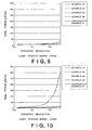
- a sample is formed by disposing the protective layer transfer sheet and an object to be transferred on top of each other, heating the thus formed assembly with a printer, which can vary gradations in the range of from 0 to 255 gradations by a gradation control method, under two levels of heating conditions of 120 gradations and 180 gradations to adhere the object to the protective layer transfer sheet, and the peel force at 180 gradations : peel force at 120 gradations ratio is preferably less than 1.4 in the peel force between the peel layer and the substrate sheet as measured when separating the sample into the protective layer transfer sheet and the object by 180 degrees.
- a printer which can vary gradations in the range of from 0 to 255 gradations by a gradation control method, under two levels of heating conditions of 120 gradations and 180 gradations to adhere the object to the protective layer transfer sheet, and the peel force at 180 gradations : peel force at 120 gradations ratio is preferably less than 1.4 in the peel force between the peel layer and the substrate sheet as measured when separating the sample into the
- Fig. 1 is a schematic cross-sectional view showing one embodiment of a protective layer transfer sheet 1 in the first aspect of the present invention.
- the construction of the protective layer transfer sheet 1 is as follows.
- a peel layer 3, a primer layer 4, and an adhesive layer 5 are laminated in this order on one side of a substrate sheet 2.
- a heat resistant slip layer 6 is provided on the other side of the substrate sheet 2.
- the three layers of the peel layer 3, the primer layer 4, and the adhesive layer 5 constitute a protective layer 7.
- the protective layer transfer sheet 1 is heated with a thermal head from the heat resistant slip layer 6 to transfer a protective layer 7 onto an object to be transferred.
- Fig. 2 is a schematic cross-sectional view showing another embodiment of the protective layer transfer sheet 1 in the first aspect of the present invention.
- the construction of the protective layer transfer sheet 1 is as follows.
- a heat resistant slip layer 6 is provided on one side of a substrate sheet 2.
- Dye layers containing sublimation dye as a thermally transferable coloring material layer are provided on the other side of the substrate sheet 2.
- the dye layers comprise three color dye layers of a yellow dye layer Y, a magenta dye layer M, and a cyan dye layer C Further, after the formation of the cyan dye layer C, a protective layer 7 comprising three layers, i.e., a peel layer 3, a primer layer 4, and an adhesive layer 5 laminated on top of each other, is formed on the other side of the substrate sheet 2 in sequence.
- the dye layers and the protective layer 7 are repeatedly provided in a side-by-side relationship with each other.
- a thermal transfer sheet comprises three color dye layers and a protective layer integrated with each other.
- Fig. 3 is a schematic cross-sectional view showing still another embodiment of the protective layer transfer sheet 1 in the first aspect of the present invention.
- the construction of the protective layer transfer sheet 1 is as follows.
- a heat resistant slip layer 6 is provided on one side of a substrate sheet 2.
- Dye layers containing sublimation dye as a thermally transferable coloring material layer are provided on the other side of the substrate sheet 2 through a primer layer 4.
- the dye layers comprise three color dye layers of a yellow dye layer Y, a magenta dye layer M, and a cyan dye layer C.
- a protective layer 7 comprising three layers, i.e., a peel layer 3, a primer layer 4, and an adhesive layer 5 laminated on top of each other, is formed on the other side of the substrate sheet 2 in sequence.
- the dye layers and the protective layer 7 are repeatedly provided in a side-by-side relationship with each other.
- This embodiment is that three color dye layers are provided on a substrate sheet through a primer layer 4, and after the formation of the cyan dye layer C, a protective layer 7 comprising three layers of a peel layer 3, a primer layer 4, and an adhesive layer 5 laminated on top of each other, is formed in sequence.
- This embodiment is also a thermal transfer sheet comprising three color dye layers and a protective layer integrated with each other.
- Fig. 4 is a schematic cross-sectional view showing a further embodiment of the protective layer transfer sheet 1 in the first aspect of the present invention.
- the construction of the protective layer transfer sheet 1 is as follows.
- a heat resistant slip layer 6 is provided on one side of a substrate sheet 2.
- Dye layers containing sublimation dye as a thermally transferable coloring material layer and a black thermal-fusion ink layer BK are provided on the other side of the substrate sheet 2.
- the dye layers comprise three color dye layers of a yellow dye layer Y, a magenta dye layer M, and a cyan dye layer C.
- a protective layer 7 comprising three layers, i.e., a peel layer 3, a primer layer 4, and an adhesive layer 5 laminated on top of each other, is formed on the other side of the substrate sheet 2 in sequence.
- the dye layers, the black thermal-fusion ink layer BK and the protective layer 7 are repeatedly provided in a side-by-side relationship with each other.
- a thermal transfer sheet comprises four-color thermally transferable coloring material layers of three dye layers and a black thermal-fusion ink layer and a protective layer integrated with each other.
- thermally transferable coloring material layer is integrated with the protective layer
- various modified embodiments are possible, for example, an embodiment wherein thermally transferable coloring material layers having other color hues in addition to Y, M, C, and BK are added, and an embodiment wherein a thermally transferable coloring material layer of BK and a protective layer are integrated with each other.
- the substrate sheet 2 of the protective layer thermal transfer sheet used in the present invention may be any conventional sheet having a certain level of heat resistance and strength.
- the thickness of the substrate sheet is, for example, from 0.5 to 50 ⁇ m, preferably from 1 to 10 ⁇ m, more preferably from 2 to 6 ⁇ m.
- polyethylene terephthalate films 1,4-polycyclohexylene dimethylene terephthalate films, polyethylene naphthalate films, polyphenylene sulfide films, polystyrene films, polypropylene films, polysulfone films, aramid films, polycarbonate films, polyvinyl alcohol films, cellophanes, cellulose derivatives such as cellulose acetate, polyethylene films, polyvinyl chloride films, nylon films, polyimide films, and ionomer films may be mentioned as specific examples of such substrate sheets.
- a polyester film formed of polyethylene terephthalate, polyethylene naphthalate, or a mixture thereof is preferred, and polyethylene terephthalate films are more preferred.
- the heat resistant slip layer 6 is provided to prevent thermal fusion of a heating device such as a thermal head to the substrate sheet and to realize smooth travelling.
- Resins usable in the heat resistant slip layer include, for example, natural resins or synthetic resins as such or in a mixture form, for example, cellulosic resins such as ethyl cellulose, hydroxy cellulose, hydroxypropyl cellulose, methyl cellulose, cellulose acetate, cellulose butyrate, and cellulose nitrate; vinyl resins such as polyvinyl alcohol, polyvinyl acetate, polyvinyl butyral, polyvinyl acetal, and polyvinyl pyrrolidone; acrylic resins such as polymethyl methacrylate, polyethyl acrylate, polyacrylamide, and acrylonitrile-styrene copolymer; aromatic polyamide resin, polyimide resin, polyamide-imide resin; polyvinyl toluene resin; coumarone-indene resin; polyester
- Slipperiness-imparting agents added to or recoated on the heat resistant slip layer formed of the above resin include phosphoric esters, metallic soaps, silicone oils, graphite powder, silicone graft polymers, fluoro graft polymers, acrylsilicone graft polymers, acrylsiloxanes, arylsiloxanes, and other silicone polymers.
- Preferred is a layer formed of a polyol, for example, a high-molecular polyalcohol compound, a polyisocyanate compound and a phosphoric ester compound. Further, the addition of a filler is more preferred.
- the heat resistant slip layer may be formed by dissolving or dispersing the above resin, slipperiness-imparting agent, and a filler in a suitable solvent to prepare a coating liquid for a heat resistant slip layer, coating the coating liquid onto a substrate sheet by forming means such as gravure printing, screen printing, or reverse roll coating using a gravure plate, and drying the coating.
- the coated amount of the heat resistant slip layer is preferably from 0.1 to 2.0 g/m 2 on a dry state.
- resins containing a reactive group of a hydroxyl group that is, a hydroxyl group-containing resin (for example, a butyral resin or an acetal resin) are used in combination with an isocyante compound or the like as a crosslinking agent to form a crosslinking resin layer.
- a hydroxyl group-containing resin for example, a butyral resin or an acetal resin
- hydroxyl group-containing resins are not particularly limited so far as they can react with the isocyanate compound.
- Such hydroxyl group-containing resins include, for example, polyvinyl butyrals, polyvinyl acetals, polyvinyl formals, polyester polyols, acryl polyols, polyether polyols, urethane polyols, and polyesters.
- polyvinyl butyrals are suitable.
- Any isocyanate compound used, for example, for conventional coating materials, adhesives, and polyurethane synthesis may be use without particular limitation.
- Such isocyanate compounds include polyisocyanates such as diisocyanate and triisocyanate.
- Specific examples of polyisocyanates used in the present invention include p-phenylene diisocyanate, 1-chloro-2,4-phenyl diisocyanate, 2-chloro-1,4-phenyl diisocyanate, 2,4-toluene diisocyanate, 2,6-toluene diisocyanate, hexamethylene diisocyanate, 4,4'-biphenylene diisocyanate, triphenylmethane triisocyanate, and 4,4,'4"-trimethyl-3,3',2'-triisocyanate-2,4,6-triphenyl cyanurate.
- the heat resistant slip layer according to the present invention is formed using a composition which is a coating liquid for a heat resistant slip layer containing an isocyanate compound and a hydroxyl group-containing resin.
- the isocyanate compound and the hdyroxyl group-containing resin contained in the heat resistant slip layer usually exist as a mutually polymerized polymer.
- the incorporation of a polyamide-imide resin in the heat resistant slip layer can improve the heat resistance and is preferred.
- the heat resistant slip layer is formed of a material comprising a mixture, as a binder, of a specific amount of a polyamide-imide resin having a Tg value of 200°C or above as measured by differential thermal analysis with a specific amount of a polyamdie-imide silicone resin and further a specific amount of a polyvalent metal salt of an alkylphosphoric ester and a specific amount of a filler mixed into the material.
- the peel layer 3 in the protective layer transfer sheet according to the present invention is formed of an acrylic copolymer resin having a solution acid value of 2 or less.
- acrylic copolymer resins include polymers produced by copolymerizing, for example, methyl methacrylate or styrene, with a monomer such as 2-hydroxyethyl methacrylate, N-methylolacrylamide, N-methylolmethacrylamide, 2-hydroxyethyl acrylate, 2-hydroxyethyl methacrylate, 2-hydroxypropyl acrylate, 2-hydroxypropyl methacrylate, 4-hydroxybutyl acrylate, 4-hydroxybutyl methacrylate, acrylic acid, methacrylic acid, 2-carboxy-1-butene, 2-carboxy-1-pentene, 2-carboxy-1-hexene, and 2-carboxy-1-heptene.
- the acid value of the acrylic copolymer resin constituting the peel layer as measured in a solution state is from 0.2 mg KOH/g to 2 mg KOH/g.
- the peel force increases between the substrate sheet and the peel layer in the protective layer transfer after long-term storage or after high-temperature storage and, consequently, separation failure takes place in the protective layer transfer.
- an acrylic copolymer resin having an acid value of from 0.2 mg KOH/g to 2 mg KOH/g a method may be adopted in which an acrylic monomer of the copolymer resin per se or an acrylic monomer composition comprising an acrylic monomer and other monomer(s) is regulated so as to have an acid value of from 0.2 mg KOH/g to 2 mg KOH/g and then polymerizing the acrylic monomer composition.
- the peel layer may contain various additives such as waxes, inorganic fine particles or organic fine particles, ultraviolet absorbers, antioxidants, and fluorescent brightening agents in such amounts that do not impair the transparency of the protective layer.
- waxes include, for example, polyethylene waxes, polyester waxes, polystyrene powders, olefin powders, microcrystalline waxes, carnauba waxes, paraffin waxes, Fischer-Tropsh waxes, various low-molecular weight polyethylenes, Japan waxes, beeswaxes, spermaceti waxes, wool waxes, shellac waxes, candelilla waxes, petrolactam, partially modified waxes, fatty acid esters, and fatty amides.
- the use of these waxes can improve the scratch resistance and layer transferability of the peel layer.
- silica, alumina, titania, and calcium carbonate are usable as the inorganic fine particle of the additive.
- Organic fine particles include styrene fine particles, acrylic fine particles, and melamine resin fine particles. The addition of these fine particles is effective in improving the layer transferability and preventing rainbow-colored unevenness.
- an ultraviolet absorber may be added to improve the lightfastness and weathering resistance of image and the like of an object covered with the protective layer.
- Ultraviolet absorbers include, for example, a wide variety of conventional organic ultraviolet absorbers, for example, salicylate, benzophenone, benzotriazole, substituted acrylonitrile, nickel chelate, or hindered amine ultraviolet absorbers.
- an ultraviolet absorbing resin produced by introducing, for example, an addition-polymerizable double bond, such as a vinyl, acryloyl, or methacryloyl group, or an alcoholic hydroxyl, amino, carboxyl, epoxy, isocyanate or other functional group, into the ultraviolet absorber may be introduced into the peel layer.
- an addition-polymerizable double bond such as a vinyl, acryloyl, or methacryloyl group
- an alcoholic hydroxyl, amino, carboxyl, epoxy, isocyanate or other functional group may be introduced into the peel layer.
- the peel layer may be formed by dissolving or dispersing the acrylic copolymer resin having a solution acid value of 2 or less in a suitable solvent such as water to prepare a coating liquid for a peel layer, coating the coating liquid, for example, by gravure printing, screen printing, or reverse roll coating using a gravure plate, on the side of the substrate sheet opposite to the side where the heat resistant slip layer is provided, and drying the coating.
- the coated amount of the peel layer is from 0.1 g/m 2 to 10 g/m 2 , preferably from 0.5 g/m 2 to 5 g/m 2 , on a dry state.
- the primer layer 4 in the present invention is provided between the peel layer and the adhesive layer on the substrate to enhance the adhesion between the peel layer and the adhesive layer.
- the primer layer used in the present invention is formed of inorganic fine particles.
- the inorganic fine particles are colloidal ultrafine particles of an inorganic pigment. Examples thereof include conventional compounds, for example, metal silicates such as aluminum silicate and magnesium silicate; metal oxides such as alumina or alumina hydrate (for example, alumina sol, colloidal alumina, cationic aluminum oxide or its hydrate, or pseudo-boehmite), silica or silica sol, magnesium oxide, and titanium oxide; carbonates such as magnesium carbonate; and the like.
- the primer layer may be formed of only one type of colloidal inorganic pigment ultrafine particles. Alternatively, two or more types of colloidal inorganic pigment ultrafine particles may be used. In any event, any colloidal inorganic pigment ultrafine particles may be used so far as they do not have a phase transition temperature up to an instantaneous highest heating temperature from a thermal head in the printing.
- the average particle diameter of the colloidal inorganic pigment ultrafine particles is generally 100 nm or less, preferably 50 nm or less, particularly preferably from 3 to 30 nm.
- a dispersion stabilizer such as hydrochloric acid or acetic acid is incorporated to bring the colloidal inorganic pigment ultrafine particles to an acidic type, fine particle charges may be rendered cationic or the colloidal inorganic pigment ultrafine particles may be surface treated.
- the colloidal inorganic pigment ultrafine particles may be commercially available products such as Aluminasol ® 100 (manufactured by Nissan Chemical Industries Ltd.) and Aluminasol ® 200 (manufactured by Nissan Chemical Industries Ltd.).
- the primer layer may be generally formed by coating a coating liquid for a primer layer, comprising colloidal inorganic pigment ultrafine particles onto a peel layer of a substrate sheet, and drying the coating. More preferably, the primer layer is formed by a sol-gel process. In the primer layer, a film is formed without use of any binder resin. Accordingly, heat resistance and toughness can be imparted to the protective layer. Further, the primer layer has good adhesion to adjacent layers (peel layer and adhesive layer). In the formation of the primer layer by the sol-gel process, the coating is dried, for example, by exposing the coating to hot air of from 90 to 130°C so that the colloidal inorganic pigment ultrafine particles are changed from a sol form to a dried gel form.
- the coating liquid for a primer layer can be prepared by dispersing colloidal inorganic pigment ultrafine particles in an aqueous medium.
- aqueous media in the coating liquid for a primer layer include water, water-soluble alcohols such as isopropyl alcohol, and mixed liquids composed of water and a water-soluble alcohol.
- aqueous media in the coating liquid for a primer layer include water, water-soluble alcohols such as isopropyl alcohol, and mixed liquids composed of water and a water-soluble alcohol.
- from 1 to 100 parts by mass of colloidal inorganic pigment ultrafine particles are contained based on 100 parts by mass of an aqueous medium.
- the primer layer according to the present invention may be composed of the above inorganic fine particles alone.
- the primer layer may comprise the above inorganic fine particles and further a water-soluble resin or an emulsifiable hydrophilic resin.
- water-soluble resins include polyvinyl pyrrolidone resins, polyvinyl alcohol resins, hydrophilic urethane resins, hydroxylalkyl substituted derivatives of cellulose, polyacrylamides, poly(meth)acrylic acids, and their metal salts.
- the addition amount of the hydrophilic resin is preferably from 0 to 50% by mass of the total solid content of the primer layer.
- the primer layer may be formed by preparing the above coating liquid, coating the coating liquid by conventional means such as gravure printing, screen printing, or reverse roll coating using a gravure plate.
- the primer layer may be coated at an amount of from 0.01 to 10 g/m 2 on a dry state.
- the coated amount on a dry state is preferably 0.05 g/m 2 or more and 1.0 g/m 2 or less from the viewpoint of imparting excellent heat resistance and toughness.
- the protective layer In addition to meeting of stable separation requirement, an improvement in "rainbow-colored unevenness" (a phenomenon in which streak unevenness of rainbow color are observed in a printing flow direction) is required in the protective layer.
- the use of the colloidal inorganic pigment ultrafine particles in the primer layer can realize better effect of preventing a printing failure of the rainbow-colored unevenness.
- the adhesive layer used in the present invention is formed on the primer layer provided in the protective layer transfer sheet according to the present invention and contains a thermoplastic resin.
- the adhesive layer has the function of adhering the protective layer to an object in the formation of a protective layer on an object such as a thermal transfer image receiving sheet using the protective layer transfer sheet according to the present invention.
- thermoplastic resin used in the adhesive layer according to the present invention is not particularly limited so far as it has adhesive properties upon heating.
- thermoplastic resins include ethylene-vinyl acetate copolymer resins, vinyl chloride-vinyl acetate copolymer resins, maleic acid-modified vinyl chloride-vinyl acetate copolymer resins, polyamide resins, polyester resins, polyethylene resins, ethylene-isobutyl acrylate copolymer resins, butyral resins, polyvinyl acetate and its copolymer resins, ionomer resins, acid-modified polyolefin resins, (meth)acrylic resins such as acrylic/methacrylic resins, acrylate resins, ethylene-(meth)acrylic acid copolymers, ethylene-(meth)acrylate copolymers, polymethyl methacrylate resins, cellulosic resins, polyvinyl ether resins, polyurethane resins, polycarbonate
- the additives described in the section of the peel layer may be used.
- the adhesive layer may be coated at an amount of from 0.1 to 10 g/m 2 on a dry state.
- the coated amount is preferably 0.5 g/m 2 or more and 5.0 g/m 2 or less on a dry state from the view point of imparting excellent adhesion.
- a protective layer having a three layer structure of the peel layer, the primer layer, and the adhesive layer, and a thermally transferable coloring material layer may be formed in sequence on an identical substrate sheet.
- This construction is advantageous in that the thermally transferable coloring material layer and the protective layer can be transferred with one head of a thermal transfer printer, the necessity of providing a plurality of units of a thermal transfer sheet feed part and a winding part can be eliminated and, thus, the size of the thermal transfer printer can be reduced, and the complication of the transfer system of the printer can be avoided.
- the thermally transferable coloring material layer may be either a coloring material layer (a thermal fusion ink layer) formed of a thermal fusion ink, or a coloring material layer (a dye layer) containing a sublimable dye.
- the thermal fusion ink used in the present invention comprises a coloring agent and a vehicle and, if necessary, various additives.
- the coloring agent among organic or inorganic pigments or dyes, those which have a color density satisfying a requirement as a recording material and do not cause color change and fading upon exposure to light, heat, temperature and the like, are preferred. Further, materials, which develop a color upon heating, and materials, which develop a color upon contact with a material coated onto an object, are also usable. Further, regarding the coloring agent, in addition to cyan, magenta, yellow, black and the like, various other color coloring agents may be used.
- the vehicle is composed mainly of wax.
- a mixture of wax with a drying oil, a resin, a mineral oil, cellulose, and a rubber derivative may also be used.
- a thermal conductive material may be incorporated in the thermally transferable coloring material layer formed of a thermal fusion ink from the view point of imparting good thermal conductivity and thermal fusion transferability.
- thermal conductive materials include carbonaceous materials such as carbon black, aluminum, copper, tin oxide, and molybdenum disulfide.
- the thermally transferable coloring material layer may be formed on the substrate film using the thermal fusion ink by conventional method such as hot melt coating, hot lacquer coating, gravure coating, gravure reverse coating, and roll coating.
- the coated amount of the thermally transferable coloring material layer formed of the thermal fusion ink may be properly determined by taking into consideration, for example, required print density and heat sensitivity and is usually from 0.1 to 30 g/m 2 on a dry state.
- the thermally transferable coloring material layer (dye layer) containing a sublimable dye is a solution or dispersion of a thermally transferable dye in a binder resin.
- the binder resin is preferably such that it has a suitable level of affinity for a dye, and, upon heating with a thermal head, the dye contained in the binder resin is sublimated and transferred (thermally transferred) onto an object. In this case, the binder resin as such is not transferred even upon heating.
- binder resins include, for example, cellulosic resins such as ethylcellulose, hydroxyethylcellulose, ethylhydroxyethylcellulose, hydroxypropylcellulose, methylcellulose, cellulose nitrate, cellulose acetate, and cellulose acetate-butyrate; vinyl resins such as polyvinyl alcohol, polyvinyl acetate, polyvinyl butyral, polyacrylamide, and polyvinylpyrrolidone; polyesters, and polyamides.
- cellulosic resins such as ethylcellulose, hydroxyethylcellulose, ethylhydroxyethylcellulose, hydroxypropylcellulose, methylcellulose, cellulose nitrate, cellulose acetate, and cellulose acetate-butyrate
- vinyl resins such as polyvinyl alcohol, polyvinyl acetate, polyvinyl butyral, polyacrylamide, and polyvinylpyrrolidone
- polyesters and polyamides.
- the content of the dye in the thermally transferable coloring material layer varies depending upon the sublimation (fusion) temperature of the dye, dyeability and the like.
- the content of the dye is preferably 30 parts or more by mass, more preferably from 30 to 300 parts by mass, based on 100 parts by mass of the binder resin.
- the content of the dye is less than 30 parts by mass, the print density and heat sensitivity are low.
- the content of the dye is more than 300 parts by mass, the storage stability and the adhesion of the thermally transferable coloring material layer onto the substrate film is lowered.
- the dye used in the thermally transferable coloring material layer is thermally fused, diffused or sublimated and is transferred onto an object, and disperse dyes are particularly preferred.
- the dye is selected by taking into consideration, for example, sublimability (fusability), hue, lightfastness, and solubility in the binder resin.
- dyes include, for example, diarylmethane dyes; triarylmethane dyes; thiazole dyes; methine dyes such as merocyanines; azomethine dyes typified by indoaniline dyes, acetophenoneazomethine dyes, pyrazoloazomethine dyes, imidazoleazomethine dyes, imidazoazomethine dyes, and pyridoneazomethine dyes; xanthene dyes; oxazine dyes; cyanomethylene dyes typified by dicyanostyrene dyes and tricyanostyrene dyes; thiazine dyes; azine dyes; acridine dyes; benzeneazo dyes; azo dyes such as pyridoneazo dyes, thiopheneazo dyes, isothiazoleazo dyes, pyrroleazo dyes, pyrrazoleazo dyes, imidazoleazo dye
- the thermally transferable coloring material layer as the dye layer may be provided on the substrate film by a conventional method, for example, by dissolving or dispersing a dye and a binder resin in a solvent to prepare an ink composition for a thermally transferable coloring material layer, and coating the ink composition onto a substrate film by a method properly selected from conventional printing methods or coating methods.
- the coated amount of the dye layer is suitably from 0.2 to 5.0 g/m 2 , preferably from 0.4 to 2.0 g/m 2 , on a dry state.
- thermally transferable coloring material layer at least two thermally transferable coloring material layers different from each other in hue should be formed in sequence on a substrate sheet.
- constructions of the two or more thermally transferable coloring material layers include a construction in which two or more dye layers using a sublimable dye are used, a construction in which a combination of thermally transferable coloring material layers of a dye layer(s) and a thermal fusion ink(s) is used, and a construction in which two or more thermally transferable coloring material layers of a thermal fusion ink are used.
- a method is particularly preferably adopted in which a yellow coloring material layer, a magenta coloring material layer, and a cyan coloring material layer are formed in sequence as sublimable dye-containing thermally transferable coloring material layers on a substrate sheet to form a high-quality thermally transferred image which is comparable to full-color photograph images and is sharp by virtue of the prevention of deviation of print length between hues in a full-color thermally transferred image.
- thermally transferred images of black color letter or pattern black can be provided by superimposing three colors of a yellow coloring material layer, a magenta coloring material layer, and a cyan coloring material layer as the dye layers.
- the additional provision of a coloring material layer formed of a black thermal fusion ink using a carbon black coloring agent on the substrate sheet is preferred. This construction can realize the formation of images which have a high black color density and are sharp.
- Fig. 5 is a schematic cross-sectional view showing second embodiment of a protective layer transfer sheet 11 in the second aspect of the present invention.
- the construction of the protective layer transfer sheet 11 is as follows. A peel layer 13 and an adhesive layer 14 are laminated in this order on one side of a substrate sheet 12. A heat resistant slip layer 15 is provided on the other side of the substrate sheet 12. The two layers of the peel layer 13 and the adhesive layer 14 constitute a protective layer 16.
- the protective layer transfer sheet 11 is heated with a thermal head from the heat resistant slip layer 15 to transfer a protective layer 16 onto an object with an image, a letter or the like formed thereon by thermal transfer.
- Fig. 6 is a schematic cross-sectional view showing another embodiment of the protective layer transfer sheet 11 in the second aspect of the present invention.
- the construction of the protective layer transfer sheet 11 is as follows.
- a heat resistant slip layer 15 is provided on one side of a substrate sheet 12.
- Dye layers containing sublimation dye as a thermally transferable coloring material layer are provided on the other side of the substrate sheet 12.
- the dye layers comprise three color dye layers of a yellow dye layer Y, a magenta dye layer M, and a cyan dye layer C
- a protective layer 16 comprising two layers, i.e., a peel layer 13 and an adhesive layer 14 laminated on top of each other, is formed on the other side of the substrate sheet 12 in sequence.
- the dye layers and the protective layer 16 are repeatedly provided in a side-by-side relationship with each other.
- a thermal transfer sheet comprises three-color dye layers and a protective layer integrated with each other.
- Fig. 7 is a schematic cross-sectional view showing still another embodiment of the protective layer transfer sheet 11 in the second aspect of the present invention.
- the construction of the protective layer transfer sheet 11 is as follows.
- a heat resistant slip layer 15 is provided on one side of a substrate sheet 12.
- Dye layers containing sublimation dye as a thermally transferable coloring material layer are provided on the other side of the substrate sheet 12 through a primer layer 17.
- the dye layers comprise three color dye layers of a yellow dye layer Y, a magenta dye layer M, and a cyan dye layer C.
- a protective layer 16 comprising three layers, i.e., a peel layer 13 and an adhesive layer 14 laminated on top of each other, is formed on the other side of the substrate sheet 12 in sequence.
- the dye layers and the protective layer 16 are repeatedly provided in a side-by-side relationship with each other.
- This embodiment is that three color dye layers are provided on a substrate sheet through a primer layer 17, and after the formation of the cyan dye layer C, a protective layer 16 comprising two layers of a peel layer 13 and an adhesive layer 14 laminated on top of each other, is formed in sequence.
- This embodiment is also a thermal transfer sheet comprising three color dye layers and a protective layer integrated with each other.
- Fig. 8 is a schematic cross-sectional view showing a further embodiment of the protective layer thermal transfer sheet 11 in the second aspect of the present invention.
- the construction of the protective layer transfer sheet 11 is as follows.
- a heat resistant slip layer 15 is provided on one side of a substrate sheet 12.
- Dye layers containing sublimation dye as a thermally transferable coloring material layer and a black thermal-fusion ink layer BK are provided on the other side of the substrate sheet 12.
- the dye layers comprise three color dye layers of a yellow dye layer Y, a magenta dye layer M, and a cyan dye layer C.
- a protective layer 16 comprising two layers, i.e., a peel layer 13 and an adhesive layer 14 laminated on top of each other, is formed on the other side of the substrate sheet 12 in sequence.
- the dye layers and the protective layer 16 are repeatedly provided in a side-by-side relationship with each other.
- a thermal transfer sheet comprises four-color thermally transferable coloring material layers of three dye layers and a black thermal-fusion ink layer and a protective layer integrated with each other.
- thermally transferable coloring material layer is integrated with the protective layer
- various modified embodiments are possible, for example, an embodiment wherein thermally transferable coloring material layers having other color hues in addition to Y, M, C, and BK are added, and an embodiment wherein a thermally transferable coloring material layer of BK and a protective layer are integrated with each other.
- the substrate sheet 12 in the protective layer thermal transfer sheet used in the present invention may be any conventional sheet having a certain level of heat resistance and strength.
- the thickness of the substrate sheet is, for example, from 0.5 to 50 ⁇ m, preferably from 1 to 10 ⁇ m, more preferably from 2 to 6 ⁇ m.
- polyethylene terephthalate films 1,4-polycyclohexylene dimethylene terephthalate films, polyethylene naphthalate films, polyphenylene sulfide films, polystyrene films, polypropylene films, polysulfone films, aramid films, polycarbonate films, polyvinyl alcohol films, cellophanes, cellulose derivatives such as cellulose acetate, polyethylene films, polyvinyl chloride films, nylon films, polyimide films, and ionomer films may be mentioned as specific examples of such substrate sheets.
- a polyester film formed of polyethylene terephthalate, polyethylene naphthalate, or a mixture thereof is preferred, and polyethylene terephthalate films are more preferred.
- the heat resistant slip layer 15 is provided on the side of the substrate sheet opposite to the side where the dye layer is provided to prevent thermal fusion of a heating device such as a thermal head to the substrate sheet and to realize smooth travelling.
- Resins usable in the heat resistant slip layer include conventional resins, for example, polyvinyl butyral resins, polyvinyl acetacetal resins, polyester resins, vinyl chloride-vinyl acetate copolymers, polyether resins, polybutadiene resins, styrene-butadiene copolymers, acryl polyols, polyurethane acrylates, polyester acrylates, polyether acrylates, epoxy acrylates, prepolymers of urethane or epoxy, nitrocellulose resins, cellulose nitrate resins, cellulose acetate propionate resins, cellulose acetate butyrate resins, cellulose acetate hydrogenphthalate resins, acetylcellulose resins, aromatic polyamide resins, polyimide resins,
- Slipperiness-imparting agents added to or recoated on the heat resistant slip layer formed of the above resin include phosphoric esters, metallic soaps, silicone oils, graphite powder, silicone graft polymers, fluoro graft polymers, acrylsilicone graft polymers, acrylsiloxanes, arylsiloxanes, and other silicone polymers.
- Preferred is a layer formed of a polyol, for example, a high-molecular polyalcohol compound, a polyisocyanate compound and a phosphoric ester compound. Further, the addition of a filler is more preferred.
- the heat resistant slip layer may be formed by dissolving or dispersing the above resin, slipperiness-imparting agent, and a filler in a suitable solvent to prepare a coating liquid for a heat resistant slip layer, coating the coating liquid onto a substrate sheet by forming means such as gravure printing, screen printing, or reverse roll coating using a gravure plate, and drying the coating.
- the coated amount of the heat resistant slip layer is preferably from 0.1 to 2.0 g/m 2 on a dry state.
- the peel layer 13 in the protective layer transfer sheet according to the present invention is formed of an acrylic copolymer resin having a solution acid value of 2 or less.
- acrylic copolymer resin having a solution acid value of 2 or less.
- resins include polymers produced by copolymerizing, for example, methyl methacrylate or styrene, with a monomer such as 2-hydroxyethyl methacrylate, N-methylolacrylamide, N-methylolmethacrylamide, 2-hydroxyethyl acrylate, 2-hydroxyethyl methacrylate, 2-hydroxypropyl acrylate, 2-hydroxypropyl methacrylate, 4-hydroxybutyl acrylate, 4-hydroxybutyl methacrylate, acrylic acid, methacrylic acid, 2-carboxy-1-butene, 2-carboxy-1-pentene, 2-carboxy-1-hexene, and 2-carboxy-1-heptene.
- the acid value of the acrylic copolymer resin constituting the peel layer as measured in a solution state is from 0.2 mg KOH/g to 2 mg KOH/g .
- the acid value is more than 2 mg KOH/g, a change in peel force between the substrate sheet and the peel layer in the protective layer transfer due to a variation in energy applied in the protective layer transfer is so large that separation failure takes place in the protective layer transfer.
- an acrylic copolymer resin having an acid value of from 0.2 mg KOH/g to 2 mg KOH/g a method may be adopted in which an acrylic monomer of the copolymer resin per se or an acrylic monomer composition comprising an acrylic monomer and other monomer(s) is regulated so as to have an acid value of from 0.2 mg KOH/g to 2 mg KOH/g and then polymerizing the acrylic monomer composition.
- the peel layer may contain various additives such as waxes, inorganic fine particles or organic fine particles, ultraviolet absorbers, antioxidants, and fluorescent brightening agents in such amounts that do not impair the transparency of the protective layer.
- waxes include, for example, polyethylene waxes, polyester waxes, polystyrene powders, olefin powders, microcrystalline waxes, carnauba waxes, paraffin waxes, Fischer-Tropsh waxes, various low-molecular weight polyethylenes, Japan waxes, beeswaxes, spermaceti waxes, wool waxes, shellac waxes, candelilla waxes, petrolactam, partially modified waxes, fatty acid esters, and fatty amides.
- the use of these waxes can improve the scratch resistance and layer transferability of the peel layer.
- silica, alumina, titania, and calcium carbonate are usable as the inorganic fine particle of the additive.
- Organic fine particles include styrene fine particles, acrylic fine particles, and melamine resin fine particles. The addition of these fine particles is effective in improving the layer transferability and preventing rainbow-colored unevenness.
- an ultraviolet absorber may be added to improve the lightfastness and weathering resistance of image and the like of an object covered with the protective layer.
- Ultraviolet absorbers include, for example, a wide variety of conventional organic ultraviolet absorbers, for example, salicylate, benzophenone, benzotriazole, substituted acrylonitrile, nickel chelate, or hindered amine ultraviolet absorbers.
- an ultraviolet absorbing resin produced by introducing, for example, an addition-polymerizable double bond, such as a vinyl, acryloyl, or methacryloyl group, or an alcoholic hydroxyl, amino, carboxyl, epoxy, isocyanate or other functional group, into the ultraviolet absorber may be introduced into the peel layer.
- an addition-polymerizable double bond such as a vinyl, acryloyl, or methacryloyl group
- an alcoholic hydroxyl, amino, carboxyl, epoxy, isocyanate or other functional group may be introduced into the peel layer.
- the peel layer may be formed by dissolving or dispersing the acrylic copolymer resin having a solution acid value of 2 or less in a suitable solvent such as water to prepare a coating liquid for a peel layer, coating the coating liquid on the side of the substrate sheet opposite to the side where the heat resistant slip layer is provided, for example, by gravure printing, screen printing, or reverse roll coating using a gravure plate, and drying the coating.
- the coated amount of the peel layer is from 0.1 g/m 2 to 10 g/m 2 , preferably from 0.5 g/m 2 to 5 g/m 2 , on a dry state.
- the adhesive layer 14 used in the present invention is formed on the peel layer provided in the protective layer transfer sheet according to the present invention and contains a thermoplastic resin.
- the adhesive layer has the function of adhering the protective layer to an object in the formation of a protective layer on an object such as a thermal transfer image receiving sheet using the protective layer transfer sheet according to the present invention.
- thermoplastic resin used in the adhesive layer according to the present invention is not particularly limited so far as it has adhesive properties upon heating.
- thermoplastic resins include, for example, ethylene-vinyl acetate copolymer resins, vinyl chloride-vinyl acetate copolymer resins, maleic acid-modified vinyl chloride-vinyl acetate copolymer resins, polyamide resins, polyester resins, polyethylene resins, ethylene-isobutyl acrylate copolymer resins, butyral resins, polyvinyl acetate and its copolymer resins, ionomer resins, acid-modified polyolefin resins, (meth)acrylic resins such as acrylic/methacrylic resins, acrylate resins, ethylene-(meth)acrylic acid copolymers, ethylene-(meth)acrylate copolymers, polymethyl methacrylate resins, cellulosic resins, polyvinyl ether resins, polyurethane resins
- the additives described in the section of the peel layer may be used.
- the adhesive layer may be coated at an amount of from 0.1 to 10 g/m 2 on a dry state.
- the coated amount is preferably 0.5 g/m 2 or more and 5.0 g/m 2 or less on a dry state from the view point of imparting excellent adhesion and the like.
- a protective layer having a two layer structure of the peel layer and the adhesive layer, and a thermally transferable coloring material layer may be formed in sequence on an identical substrate sheet.
- This construction is advantageous in that the thermally transferable coloring material layer and the protective layer can be transferred with one head of a thermal transfer printer, the necessity of providing a plurality of units of a thermal transfer sheet feed part and a winding part can be eliminated and, thus, the size of the thermal transfer printer can be reduced, and the complication of the transfer system of the printer can be avoided.
- the thermally transferable coloring material layer may be either a coloring material layer (a thermal fusion ink layer) formed of a thermal fusion ink, or a coloring material layer (a dye layer) containing a sublimable dye.
- the thermal fusion ink used in the present invention comprises a coloring agent and a vehicle and, if necessary, various additives.
- the coloring agent among organic or inorganic pigments or dyes, those which have a color density satisfying a requirement as a recording material and do not cause color change and fading upon exposure to light, heat, temperature and the like, are preferred. Further, materials, which develop a color upon heating, and materials, which develop a color upon contact with a material coated onto an object, are also usable. Further, regarding the coloring agent, in addition to cyan, magenta, yellow, black and the like, various other color coloring agents may be used.
- the vehicle is composed mainly of wax.
- a mixture of wax with a drying oil, a resin, a mineral oil, cellulose, a rubber derivative or the like may also be used.
- a thermal conductive material may be incorporated in the thermally transferable coloring material layer formed of a thermal fusion ink from the view point of imparting good thermal conductivity and thermal fusion transferability.
- thermal conductive materials include carbonaceous materials such as carbon black, aluminum, copper, tin oxide, and molybdenum disulfide.
- the thermally transferable coloring material layer may be formed on the substrate film using the thermal fusion ink by conventional method such as hot melt coating, hot lacquer coating, gravure coating, gravure reverse coating, and roll coating.
- the coated amount of the thermally transferable coloring material layer formed of the thermal fusion ink may be properly determined by taking into consideration, for example, required print density and heat sensitivity and is usually from 0.1 to 30 g/m 2 on a dry state.
- the thermally transferable coloring material layer (dye layer) containing a sublimable dye is a dispersion or solution of a thermally transferable dye in a binder resin.
- the binder resin is preferably such that it has a suitable level of affinity for a dye, and, upon heating with a thermal head, the dye contained in the binder resin is sublimated and transferred (thermally transferred) onto an object. In this case, the binder resin as such is not transferred even upon heating.
- binder resins include, for example, cellulosic resins such as ethylcellulose, hydroxyethylcellulose, ethyl hyd roxyethylcellu lose, hydroxypropylcellulose, methylcellulose, cellulose nitrate, cellulose acetate, and cellulose acetate butyrate; vinyl resins such as polyvinyl alcohol, polyvinyl acetate, polyvinyl butyral, polyacrylamide, and polyvinylpyrrolidone; polyesters, and polyamides.
- cellulosic resins such as ethylcellulose, hydroxyethylcellulose, ethyl hyd roxyethylcellu lose, hydroxypropylcellulose, methylcellulose, cellulose nitrate, cellulose acetate, and cellulose acetate butyrate
- vinyl resins such as polyvinyl alcohol, polyvinyl acetate, polyvinyl butyral, polyacrylamide, and polyvinyl
- the content of the dye in the thermally transferable coloring material layer varies depending upon the sublimation (fusion) temperature of the dye, dyeability and the like.
- the content of the dye is preferably 30 parts or more by mass, more preferably from 30 to 300 parts by mass, based on 100 parts by mass of the binder resin.
- the content of the dye is less than 30 parts by mass, the print density and heat sensitivity are low.
- the content of the dye is more than 300 parts by mass, the storage stability and the adhesion of the thermally transferable coloring material layer onto the substrate film is lowered.
- the dye used in the thermally transferable coloring material layer is thermally fused, diffused or sublimated and is transferred onto an object, and disperse dyes are particularly preferred.
- the dye is selected by taking into consideration, for example, sublimability (fusability), hue, lightfastness, and solubility in the binder resin.
- dyes include, for example, diarylmethane dyes; triarylmethane dyes; thiazole dyes; methine dyes such as merocyanines; azomethine dyes typified by indoaniline dyes, acetophenoneazomethine dyes, pyrazoloazomethine dyes, imidazoleazomethine dyes, imidazoazomethine dyes, and pyridoneazomethine dyes; xanthene dyes; oxazine dyes; cyanomethylene dyes typified by dicyanostyrene dyes and tricyanostyrene dyes; thiazine dyes; azine dyes; acridine dyes; benzeneazo dyes; azo dyes such as pyridoneazo dyes, thiopheneazo dyes, isothiazoleazo dyes, pyrroleazo dyes, pyrrazoleazo dyes, imidazoleazo dye
- the thermally transferable coloring material layer as the dye layer may be provided on the substrate film by a conventional method, for example, by dissolving or dispersing a dye and a binder resin in a solvent to prepare an ink composition for a thermally transferable coloring material layer, and coating the ink composition onto a substrate film by a method properly selected from conventional printing methods or coating methods.
- the coated amount of the dye layer is suitably from 0.2 to 5.0 g/m 2 , preferably from 0.4 to 2.0 g/m 2 , on a dry state.
- thermally transferable coloring material layer at least two thermally transferable coloring material layers different from each other in hue should be formed in sequence on a substrate sheet.
- constructions of the two or more thermally transferable coloring material layers include a construction in which two or more dye layers using a sublimable dye are used, a construction in which a combination of thermally transferable coloring material layers of a dye layer(s) and a thermal fusion ink(s) is used, and a construction in which two or more thermally transferable coloring material layers of a thermal fusion ink are used.
- a method is particularly preferably adopted in which a yellow coloring material layer, a magenta coloring material layer, and a cyan coloring material layer are formed in sequence as sublimable dye-containing thermally transferable coloring material layers on a substrate sheet to form a high-quality thermally transferred image which is comparable to full-color photograph images and is sharp by virtue of the prevention of deviation of print length between hues in a full-color thermally transferred image.
- thermally transferred images of black color letter or pattern black can be provided by superimposing three colors of a yellow coloring material layer, a magenta coloring material layer, and a cyan coloring material layer as the dye layers.
- the additional provision of a coloring material layer formed of a black thermal fusion ink using a carbon black coloring agent on the substrate sheet is preferred. This construction can realize the formation of images which have a high black color density and are sharp.
- a primer layer 17 can also be formed by coating between the substrate sheet and the thermally transferable coloring material layer and/or between the substrate sheet and the heat resistant slip layer.
- the primer layer may be formed of the following resin.
- resins include polyester resins, plyacrylic ester resins, polyvinyl acetate resins, polyurethane resins, styrene acrylate resins, polyacrylamide resins, polyamide resins, polyether resins, polystyrene resins, polyethylene resins, polypropylene resins, vinyl resins such as polyvinyl chloride resins, polyvinyl alcohol resins and polyvinylidene chloride resins, polyvinyl acetal resins such as polyvinyl acetoacetal and polyvinyl butyral, and cellulosic resins.
- the primer layer may be formed by a method properly selected from conventional printing methods and coating methods.
- the coated amount of the primer layer is from 0.2 to 5.0 g/m 2 , preferably from
- a protective layer may be transferred onto any object so far as a thermally transferred image can be formed on the object.
- the object and the protective layer transfer sheet are disposed on top of each other followed by heating to adhere both the object and the protective layer transfer sheet to each other and thus to prepare an assembly.
- the protective layer transfer sheet is then separated from the object.
- the heating is performed with a test printer of a multi-pulse system, which has such a pulse length that one line period has been divided into 256 equal parts and wherein the number of divided pulses could be varied from 0 to 255 during one line period, by a gradation control method, under two levels of heating conditions of 120 pulse number (gradations) and 180 pulse number (gradations).
- the peel force at 180 gradations peel force at 120 gradations ratio is less than 1.4 in the peel force between the peel layer and the substrate sheet as measured when separating the sample into the protective layer transfer sheet and the object by 180 degrees.
- An example of the object is one having a construction comprising a conventional (dye) receptive layer provided on a substrate formed of various papers or plastic sheets.
- the substrate has dyeing property with a dye, that is, when the substrate is formed of, for example, a flexible polyvinyl chloride resin, there is no need to provide any receptive layer and, in this case, the substrate as such may be used as the object.
- Such various papers include, for example, capacitor papers, glassine papers, parchment papers, or papers having a high sizing degree, synthetic papers (polyolefin or polystyrene papers), woodfree papers, art papers, coated papers, cast coated papers, wall papers, backing papers, synthetic resin- or emulsion-impregnated papers, synthetic rubber latex impregnated papers, synthetic resin internally added papers, board papers, and cellulose fiber papers.
- synthetic papers polyolefin or polystyrene papers
- woodfree papers art papers
- coated papers coated papers
- cast coated papers wall papers
- backing papers synthetic resin- or emulsion-impregnated papers
- synthetic rubber latex impregnated papers synthetic resin internally added papers
- board papers and cellulose fiber papers.
- Such various plastic sheets include, for example, polyesters, polyacrylates, polycarbonates, polyurethanes, polyimides, polyetherimides, cellulose derivatives, polyethylenes, ethylene-vinyl acetate copolymers, polypropylenes, polystyrenes, acrylic resins, polyvinyl chlorides, polyvinylidene chlorides, polyvinyl alcohols, polyvinyl butyrals, nylons, polyether ether ketones, polysulfones, polyether sulfones, tetrafluoroethylene/perfluoroalkyl vinyl ethers, polyvinyl fluorides, tetrafluoroethylene/ethylenes, tetrafluoroethylene/hexafluoropropylenes, polychlorotrifluoroethylenes, and polyvinylidene fluorides.
- White opaque sheets (films) obtained by adding a white pigment or a filler to the synthetic resin and forming a film from the mixture, or porous sheets (films) comprising microvoids in the inside of a substrate may also be used as the plastic sheet, and the plastic sheet is not particularly limited.
- a laminate comprising any combination of substrates of the above papers and plastic sheets may also be used.
- Typical examples of such laminates include a laminate of a cellulose fiber paper and a synthetic paper or a laminate of a cellulose fiber paper and a plastic sheet.
- the thickness of the object may be optionally selected and is generally about from 10 to 300 ⁇ m.
- a sample is formed by disposing the protective layer transfer sheet and an object on top of each other, and heating the assembly to bond the object and the protective layer transfer sheet to each other with a printer, which can vary gradations in the range of 0 to 255 gradations by a gradation control method, under two levels of heating conditions of 120 gradations and 180 gradations.
- the peel force at 180 gradations peel force at 120 gradations ratio is less than 1.4 in the peel force as measured when separating the protective layer transfer sheet from the object to reduce the peel force.
- printing conditions such as electric resistance value, print density, printing voltage, printing speed, and printing start temperature of the thermal head may be varied.
- the following coating liquid for a heat resistant slip layer was coated by using a gravure coater on one side of a substrate sheet of a 6 ⁇ m-thick continuous sheet of polyethylene terephthalate (Lumirror ® , manufactured by Toray Industries, Inc.) at an amount of 1.0 g/m 2 in terms of a solid content, and the coating was dried to form a heat resistant slip layer.
- a gravure coater on one side of a substrate sheet of a 6 ⁇ m-thick continuous sheet of polyethylene terephthalate (Lumirror ® , manufactured by Toray Industries, Inc.) at an amount of 1.0 g/m 2 in terms of a solid content, and the coating was dried to form a heat resistant slip layer.
- an ink having the following composition was coated by using a gravure coater on the side of the substrate sheet opposite to the side where the heat resistant slip layer is provided to form a thermally transferable coloring material layer formed of dye layers, in which three colors constitute one set, so that each color has a size of 8 cm in length and 4 cm in width. In this case, the distance between individual sets was brought to 10 cm.
- the coated amount of the dye layer was 2.0 g/m 2 on a dry state for each of the three colors.
- the following coating liquid for a peel layer was coated by using a gravure coater between individual sets of the dye layer so that the coated amount of the peel layer was 1.0 g/m 2 on a dry state.
- the following coating liquid for a primer layer was coated by using a gravure coater on the peel layer so that the coated amount of the primer layer was 0.2 g/m 2 on a dry state.
- ⁇ Coating liquid for primer layer> Aluminasol 8.0 parts (Aluminasol 200 ® , average particle diameter: 10 to 20 nm, acetic acid stabilization type, manufactured by Nissan Chemical Industries Ltd.) Polyvinyl pyrrolidone resin 2.0 parts (PVP-K90 ® , manufactured by ISP Japan Ltd.) Water 45.0 parts Isopropyl alcohol 45.0 parts
- Example A1 The following coating liquid for an adhesive layer was coated by using a gravure coater on the primer layer so that of the coated amount of the adhesive layer was 1.0 g/m 2 on a dry state.
- a protective layer transfer sheet of Example A1 was produced.
- the positions of the protective layer and the thermally transferable coloring material layer are the same as those shown in Fig. 2 .
- ⁇ Coating liquid for adhesive layer> Vinyl chloride-vinyl acetate copolymer 50 parts (SOLVIN CNL ® , manufactured by Nisshin Chemical Industries Ltd.) Toluene 50 parts Methyl ethyl ketone 50 parts
- a protective layer transfer sheet of Example A2 was produced in the same manner as in Example A1, except that the coating liquid for a peel layer of the protective layer transfer sheet of Example A1 was changed to the following coating liquid.
- a protective layer transfer sheet of Example A3 was produced in the same manner as in Example A1, except that the coating liquid for a peel layer of the protective layer transfer sheet of Example A1 was changed to the following coating liquid.
- a protective layer transfer sheet of Example A4 was produced in the same manner as in Example A2, except that the coating liquid for a heat resistant slip layer of the protective layer transfer sheet of Example A2 was changed to the following coating liquid and the coated amount of the heat resistant slip layer was brought to 0.5 g/m 2 in terms of a solid content.
- a protective layer transfer sheet of Comparative Example A1 was produced in the same manner as in Example A1, except that the coating liquid for a peel layer of the protective layer transfer sheet of Example A1 was changed to the following coating liquid.
- ⁇ Coating liquid for peel layer> Polymethyl methacrylate resin 20 parts (acid value of solution 3.1 (mg KOH/g)) (DIANAL ® BR-87, manufactured by Mitsubishi Rayon Co., Ltd) Toluene 40 parts Methyl ethyl ketone 40 parts
- the protective layer comprising the peel layer, the primer layer, and the adhesive layer of the protective layer transfer sheet produced in the above Examples and Comparative Example was transferred on an image receiving surface of a thermal transfer image-receiving sheet to form a protective layer. In this case, the separability of the protective layer transfer sheet was evaluated.
- the evaluation was carried out by the following method.
- the peel force necessary for separating the protective layer transfer sheet from the thermal transfer image receiving sheet was measured using the sample in such a state that the thermal transfer image receiving sheet and the protective layer transfer sheet had been bonded to each other.
- the peel force was measured as a peel force necessary for 180-degree peeling with the following device.
- the peel force was measured using two samples one of which had been allowed to stand at room temperature (20°C) and the other had been stored for 30 days in an atmosphere of temperature 40°C and humidity 90% RH.
- the results of measurement of the peel force mean that the protective layer transfer sheets of the Examples can prevent separation failure of the protective layer transfer caused by increased peel force between the substrate sheet and the peel layer, whereas, for the protective layer transfer sheet of the Comparative Example, after storage at elevated temperatures, the separation failure of the protective layer transfer takes place due to increased peel force between the substrate sheet and the peel layer.
- the components in the primer layer migrate into the substrate sheet/peel layer interface to affect the peel force, that is, the components in the primer layer do not react with the peel layer and substrate sheet using an acrylic resin having a solution acid value of 2 or less to not cause a peel force change, whereas the components in the primer layer react with the peel layer and substrate sheet using an acrylic resin having a solution acid value of more than 2 to cause an increased peel force.
- Figs. 9 and 10 show the results of measurement of the peel force on two pulse number levels in the protective layer transfer, that is, a pulse number of 125 and a pulse number of 230.
- Fig. 9 shows the relationship between the pulse number (transfer gradation) in the protective layer transfer in the sample which had been allowed to stand at room temperature (20°C), and the peel force, that is, a change of peel force upon a continuous variation of pulse number.
- Fig. 10 shows the relationship between the pulse number (transfer gradation) of the protective layer transfer in the sample stored in an atmosphere of temperature 40°C and humidity 90% RH for 30 days and the peel force, that is, a change of peel force upon a continuous variation of pulse number.
- the following coating liquid for a heat resistant slip layer was coated by using a gravure coater on one side of a substrate sheet of a 6 ⁇ m-thick continuous sheet of polyethylene terephthalate (Lumirror ® , manufactured by Toray Industries, Inc.) at an amount of 1.0 g/m 2 in terms of a solid content, and the coating was dried to form a heat resistant slip layer.
- a gravure coater on one side of a substrate sheet of a 6 ⁇ m-thick continuous sheet of polyethylene terephthalate (Lumirror ® , manufactured by Toray Industries, Inc.) at an amount of 1.0 g/m 2 in terms of a solid content, and the coating was dried to form a heat resistant slip layer.
- an ink having the following composition was coated by using a gravure coater on the side of the substrate sheet opposite to the side where the heat resistant slip layer is provided to form a thermally transferable coloring material layer formed of dye layers, in which three colors constitute one set, so that each color has a size of 8 cm in length and 4 cm in width. In this case, the distance between individual sets was brought to 10 cm.
- the coated amount of the dye layer was 2.0 g/m 2 on a dry state for each of the three colors.
- the following coating liquid for a peel layer was coated by using a gravure coater between individual sets of the dye layer so that the coated amount of the peel layer was 1.0 g/m 2 on a dry state.
- Example B1 The following coating liquid for an adhesive layer was coated by using a gravure coater on the peel layer so that the coated amount of the adhesive layer was 1.0 g/m 2 on a dry state.
- a protective layer transfer sheet of Example B1 was produced.
- the positions of the protective layer and the thermally transferable coloring material layer are the same as those shown in Fig. 6 .
- ⁇ Coating liquid for adhesive layer> Vinyl chloride-vinyl acetate copolymer 50 parts (SOLVIN ® CNL, manufactured by Nisshin Chemical Industries Ltd.) Toluene 50 parts Methyl ethyl ketone 50 parts
- a protective layer transfer sheet of Example B2 was produced in the same manner as in Example B1, except that the coating liquid for a peel layer of the protective layer transfer sheet of Example B1 was changed to the following coating liquid.
- a protective layer transfer sheet of Example B3 was produced in the same manner as in Example B1, except that the coating liquid for a peel layer of the protective layer transfer sheet of Example B1 was changed to the following coating liquid.
- a protective layer transfer sheet of Comparative Example B1 was produced in the same manner as in Example B1, except that the coating liquid for a peel layer in the protective layer transfer sheet of Example B1 was changed to the following coating liquid.
- ⁇ Coating liquid for peel layer> Polymethyl methacrylate resin 20 parts (acid value of solution 3.1 (mg KOH/g)) (DIANAL ® BR-87, manufactured by Mitsubishi Rayon Co., Ltd) Toluene 40 parts Methyl ethyl ketone 40 parts
- the protective layer comprising a peel layer and an adhesive layer in each of the protective layer transfer sheets produced in the Examples and Comparative Examples was transferred onto a receptive layer of a thermal transfer image receiving sheet (a sheet obtained by cutting an image receiving sheet for a Canon ® compact photoprinter CP 710 into an arbitrary size) with a test printer under the following conditions to prepare a "sample composed of the protective layer transfer sheet and the thermal transfer image receiving sheet bonded to each other," and the peel force was measured under the following conditions.
- a thermal transfer image receiving sheet a sheet obtained by cutting an image receiving sheet for a Canon ® compact photoprinter CP 710 into an arbitrary size
- the peel force necessary for separating the protective layer transfer sheet from the object was measured using the sample in such a state that the object and the protective layer transfer sheet had been bonded to each other.
- the peel force was measured as a peel force necessary for 180-degree peeling with the following device.
- a tape (Scotch ® Mending Tape MP-18) was applied onto the surface of the protective layer (adhesive layer). 10 min after the application, the tape was separated in a 90-degree direction at a rate of 0.6 m/min to inspect the sample for abnormal separation and thus to examine the adhesion between the protective layer and the substrate sheet, and the results were evaluated according to the following criteria.
- a protective layer was transferred onto an object with an image formed by thermal transfer using each of the protective layer transfer sheets of the Examples and the Comparative Example under the following conditions.
- the print with the protective layer transferred thereon was superimposed on a flexible vinyl chloride sheet containing a plasticizer added thereto (manufactured by Mitsubishi Chemical Corporation, Arutoron#480 ® , thickness 400 ⁇ m) so that the image face of the print faced the vinyl chloride sheet.
- a load of 70.2 g/cm 2 was applied to the assembly followed by storage under an environment of 50°C for 48 hr. Thereafter, a deterioration in image by the plasticizer was visually evaluated according to the following criteria.
- the peel force at 180 gradations is 1.3 times the peel force at 120 gradations and does not reach 1.4 times the peel force at 120 gradations. This indicates that, even when the applied energy in the protective layer transfer is increased, suppressed peel force, freedom from transfer failure of the protective layer, and stable transfer of the protective layer can be realized.
- the peel force at 180 gradations is 1.5 times the peel force at 120 gradations, that is, is more than 1.4 times the peel force at 120 gradations. This indicates that, when the applied energy is increased in the protective layer transfer, separation failure in the protective layer transfer takes place due to increased peel force between the substrate sheet and the peel layer.
- the evaluation of the adhesion and the plasticizer resistance was good.
- the peel layer of each of the protective layer transfer sheets of Examples B1, B2 and B3 is formed of an acrylic copolymer resin having a solution acid value of 2 or less, even when the applied energy in the protective layer transfer is increased, the peel layer does not react with the substrate sheet and an increase in peel force is suppressed.
- the peel layer in the protective layer transfer sheet of Comparative Example B1 is formed of an acrylic resin having a solution acid value of more than 2, and it is considered that, when the applied energy in the protective layer transfer is increased, the peel layer reacts with the substrate sheet resulting in increased peel force.
Claims (5)
- Schutzschichtübertragungsfolie (1, 11), umfassend: eine Substratfolie (2, 12), eine wärmebeständige Gleitschicht (6, 15), die auf einer Seite der Substratfolie (2, 12) bereitgestellt ist, und eine thermisch übertragbare Schutzschicht (7, 16), die auf mindestens einem Teil der anderen Seite der Substratfolie (2, 12) gegenüber der einen Seite bereitgestellt ist, auf der die wärmebeständige Gleitschicht (6, 15) bereitgestellt ist,
wobei die Schutzschicht (7, 16) eine Ablöseschicht (3, 13) und eine Haftschicht (5, 14) umfasst, die in dieser Reihenfolge ausgehend von der Seite der Substratfolie ausgebildet sind, und die Ablöseschicht (3, 13) ein Acrylcopolymerharz mit einem Lösungssäurewert von 0,2 mg KOH/g bis 2 mg KOH/g aufweist. - Schutzschichtübertragungsfolie (1, 11) nach Anspruch 1, die ferner eine Haftvermittlerschicht (4) umfasst, die zwischen der Ablöseschicht (3, 13) und der Haftschicht (5, 14) ausgebildet ist.
- Schutzschichtübertragungsfolie (1, 11) nach Anspruch 2, bei der die Haftvermittlerschicht (4) unter Verwendung einer Zusammensetzung ausgebildet worden ist, die kolloidale ultrafeine Teilchen eines Aluminiumoxidsols enthält.
- Schutzschichtübertragungsfolie (1, 11) nach einem der Ansprüche 1 bis 3, bei der die wärmebeständige Gleitschicht (6, 15) unter Verwendung einer Zusammensetzung ausgebildet worden ist, die eine Isocyanatverbindung und ein Hydroxylgruppe-enthaltendes Harz enthält.
- Schutzschichtübertragungsfolie (1, 11) nach einem der Ansprüche 1 bis 3, bei der die wärmebeständige Gleitschicht (6, 15) ein Polyamidimidharz enthält.
Applications Claiming Priority (2)
| Application Number | Priority Date | Filing Date | Title |
|---|---|---|---|
| JP2007231676A JP5104138B2 (ja) | 2007-09-06 | 2007-09-06 | 保護層転写シート |
| JP2007252394A JP2009083137A (ja) | 2007-09-27 | 2007-09-27 | 保護層転写シート |
Publications (2)
| Publication Number | Publication Date |
|---|---|
| EP2033803A1 EP2033803A1 (de) | 2009-03-11 |
| EP2033803B1 true EP2033803B1 (de) | 2014-03-19 |
Family
ID=40044073
Family Applications (1)
| Application Number | Title | Priority Date | Filing Date |
|---|---|---|---|
| EP08015704.3A Active EP2033803B1 (de) | 2007-09-06 | 2008-09-05 | Schutzschichtübertragungsfolie |
Country Status (2)
| Country | Link |
|---|---|
| US (1) | US20090068456A1 (de) |
| EP (1) | EP2033803B1 (de) |
Families Citing this family (6)
| Publication number | Priority date | Publication date | Assignee | Title |
|---|---|---|---|---|
| CA2620845C (en) * | 2005-08-31 | 2013-11-19 | Transilwrap Company, Inc. | Intrusion resistant thermal laminating film |
| CN103253015B (zh) * | 2013-05-24 | 2015-09-30 | 云南玉溪东魅包装材料有限公司 | 一种镭射热转印碳带及其制备方法 |
| KR101665164B1 (ko) * | 2013-11-29 | 2016-10-12 | 제일모직주식회사 | 편광판용 점착 필름, 이를 포함하는 편광판 및 이를 포함하는 광학표시장치 |
| WO2016043236A1 (ja) * | 2014-09-16 | 2016-03-24 | 大日本印刷株式会社 | 転写シート |
| JP6213857B1 (ja) | 2016-03-31 | 2017-10-18 | 大日本印刷株式会社 | 熱転写シート |
| US20220333309A1 (en) * | 2021-04-20 | 2022-10-20 | Celanese International Corporation | Coated Film For Laminating Substrates Made From Biodegradable Materials |
Family Cites Families (12)
| Publication number | Priority date | Publication date | Assignee | Title |
|---|---|---|---|---|
| US3502497A (en) * | 1964-08-26 | 1970-03-24 | Johnson & Johnson | Pressure-sensitive adhesive product |
| JP2999515B2 (ja) | 1990-05-31 | 2000-01-17 | 大日本印刷株式会社 | 熱転写カバーフイルム |
| JP3096691B2 (ja) | 1990-10-04 | 2000-10-10 | 大日本印刷株式会社 | 熱転写カバーフイルム |
| JP3486050B2 (ja) * | 1996-04-23 | 2004-01-13 | 株式会社リンレイ | 可剥離性コーティング剤水分散物 |
| JP3776715B2 (ja) * | 2000-03-24 | 2006-05-17 | 大日本印刷株式会社 | 熱転写シート |
| JP4336176B2 (ja) * | 2003-09-30 | 2009-09-30 | 大日本印刷株式会社 | 熱転写シート |
| TWI275110B (en) * | 2004-08-10 | 2007-03-01 | Tdk Corp | Paste for releasable layer, and method of manufacturing laminated electronic component |
| WO2006046566A1 (ja) * | 2004-10-25 | 2006-05-04 | Dai Nippon Printing Co., Ltd. | 熱転写シート及び保護層転写シート |
| JP4542458B2 (ja) | 2005-03-30 | 2010-09-15 | 大日本印刷株式会社 | 保護層熱転写シート |
| US8187999B2 (en) * | 2005-03-31 | 2012-05-29 | Dai Nippon Printing Co., Ltd. | Thermal transfer sheet |
| JP4743417B2 (ja) | 2006-03-02 | 2011-08-10 | 清水建設株式会社 | 止水装置と貫通孔の形成方法 |
| JP2007252394A (ja) | 2006-03-20 | 2007-10-04 | Samii Kk | 回胴式遊技機 |
-
2008
- 2008-09-02 US US12/202,512 patent/US20090068456A1/en not_active Abandoned
- 2008-09-05 EP EP08015704.3A patent/EP2033803B1/de active Active
Also Published As
| Publication number | Publication date |
|---|---|
| US20090068456A1 (en) | 2009-03-12 |
| EP2033803A1 (de) | 2009-03-11 |
Similar Documents
| Publication | Publication Date | Title |
|---|---|---|
| EP1637340B1 (de) | Thermisches Transferblatt | |
| EP1958787B1 (de) | Wärmeübertragungsblatt | |
| JP4816518B2 (ja) | 熱転写シート | |
| EP2679394B1 (de) | Wärmeübertragungsfolie | |
| EP2902191B1 (de) | Übertragungsblatt mit schutzschicht | |
| EP2033803B1 (de) | Schutzschichtübertragungsfolie | |
| EP2937222B1 (de) | Thermotransferfolie | |
| US10737520B2 (en) | Thermal transfer sheet | |
| JP2012006342A (ja) | 熱転写シート | |
| JP5104138B2 (ja) | 保護層転写シート | |
| EP0927644A1 (de) | Wärmeübertragungsbild aufnehmendes Blatt | |
| EP1228894B1 (de) | Schutzschichtübertragungsfilm und Bilddruckmaterial | |
| EP3263352B1 (de) | Sublimationswärmeübertragungsfolie | |
| JP5297741B2 (ja) | 保護層転写シート | |
| EP1219461B1 (de) | Wärmeempfindliches Übertragungsblatt | |
| EP1092562B1 (de) | Schutzschichtübertragungsblatt | |
| JP2009083137A (ja) | 保護層転写シート | |
| CN111683819B (zh) | 热转印片、中间转印介质与热转印片的组合、印相物的制造方法以及装饰物 | |
| JP2015066781A (ja) | 熱転写シートと熱転写受像シートとの組合せ、及び画像形成方法 | |
| JP2019177666A (ja) | 熱転写受像シート、熱転写受像シートの製造に用いる熱転写シート | |
| JP2015066775A (ja) | 熱転写シートと熱転写受像シートとの組合せ、及び画像形成方法 |
Legal Events
| Date | Code | Title | Description |
|---|---|---|---|
| PUAI | Public reference made under article 153(3) epc to a published international application that has entered the european phase |
Free format text: ORIGINAL CODE: 0009012 |
|
| AK | Designated contracting states |
Kind code of ref document: A1 Designated state(s): AT BE BG CH CY CZ DE DK EE ES FI FR GB GR HR HU IE IS IT LI LT LU LV MC MT NL NO PL PT RO SE SI SK TR |
|
| AX | Request for extension of the european patent |
Extension state: AL BA MK RS |
|
| 17P | Request for examination filed |
Effective date: 20090604 |
|
| AKX | Designation fees paid |
Designated state(s): DE FR GB |
|
| 17Q | First examination report despatched |
Effective date: 20091210 |
|
| GRAP | Despatch of communication of intention to grant a patent |
Free format text: ORIGINAL CODE: EPIDOSNIGR1 |
|
| RIC1 | Information provided on ipc code assigned before grant |
Ipc: B41M 5/44 20060101AFI20131008BHEP Ipc: B41M 7/00 20060101ALI20131008BHEP |
|
| INTG | Intention to grant announced |
Effective date: 20131105 |
|
| GRAS | Grant fee paid |
Free format text: ORIGINAL CODE: EPIDOSNIGR3 |
|
| GRAA | (expected) grant |
Free format text: ORIGINAL CODE: 0009210 |
|
| AK | Designated contracting states |
Kind code of ref document: B1 Designated state(s): DE FR GB |
|
| REG | Reference to a national code |
Ref country code: GB Ref legal event code: FG4D |
|
| REG | Reference to a national code |
Ref country code: DE Ref legal event code: R096 Ref document number: 602008030929 Country of ref document: DE Effective date: 20140430 |
|
| REG | Reference to a national code |
Ref country code: DE Ref legal event code: R097 Ref document number: 602008030929 Country of ref document: DE |
|
| PLBE | No opposition filed within time limit |
Free format text: ORIGINAL CODE: 0009261 |
|
| STAA | Information on the status of an ep patent application or granted ep patent |
Free format text: STATUS: NO OPPOSITION FILED WITHIN TIME LIMIT |
|
| 26N | No opposition filed |
Effective date: 20141222 |
|
| REG | Reference to a national code |
Ref country code: DE Ref legal event code: R097 Ref document number: 602008030929 Country of ref document: DE Effective date: 20141222 |
|
| REG | Reference to a national code |
Ref country code: FR Ref legal event code: PLFP Year of fee payment: 9 |
|
| REG | Reference to a national code |
Ref country code: FR Ref legal event code: PLFP Year of fee payment: 10 |
|
| REG | Reference to a national code |
Ref country code: FR Ref legal event code: PLFP Year of fee payment: 11 |
|
| P01 | Opt-out of the competence of the unified patent court (upc) registered |
Effective date: 20230524 |
|
| PGFP | Annual fee paid to national office [announced via postgrant information from national office to epo] |
Ref country code: GB Payment date: 20230920 Year of fee payment: 16 |
|
| PGFP | Annual fee paid to national office [announced via postgrant information from national office to epo] |
Ref country code: FR Payment date: 20230928 Year of fee payment: 16 Ref country code: DE Payment date: 20230920 Year of fee payment: 16 |