EP0647535A1 - Verfahren zum Erkennen eines leeren Reifens an einem Fahrzeug - Google Patents
Verfahren zum Erkennen eines leeren Reifens an einem Fahrzeug Download PDFInfo
- Publication number
- EP0647535A1 EP0647535A1 EP94307340A EP94307340A EP0647535A1 EP 0647535 A1 EP0647535 A1 EP 0647535A1 EP 94307340 A EP94307340 A EP 94307340A EP 94307340 A EP94307340 A EP 94307340A EP 0647535 A1 EP0647535 A1 EP 0647535A1
- Authority
- EP
- European Patent Office
- Prior art keywords
- vehicle
- del
- factor
- wheel
- clockwise
- Prior art date
- Legal status (The legal status is an assumption and is not a legal conclusion. Google has not performed a legal analysis and makes no representation as to the accuracy of the status listed.)
- Granted
Links
Images

Classifications
-
- B—PERFORMING OPERATIONS; TRANSPORTING
- B60—VEHICLES IN GENERAL
- B60C—VEHICLE TYRES; TYRE INFLATION; TYRE CHANGING; CONNECTING VALVES TO INFLATABLE ELASTIC BODIES IN GENERAL; DEVICES OR ARRANGEMENTS RELATED TO TYRES
- B60C23/00—Devices for measuring, signalling, controlling, or distributing tyre pressure or temperature, specially adapted for mounting on vehicles; Arrangement of tyre inflating devices on vehicles, e.g. of pumps or of tanks; Tyre cooling arrangements
- B60C23/06—Signalling devices actuated by deformation of the tyre, e.g. tyre mounted deformation sensors or indirect determination of tyre deformation based on wheel speed, wheel-centre to ground distance or inclination of wheel axle
- B60C23/061—Signalling devices actuated by deformation of the tyre, e.g. tyre mounted deformation sensors or indirect determination of tyre deformation based on wheel speed, wheel-centre to ground distance or inclination of wheel axle by monitoring wheel speed
-
- B—PERFORMING OPERATIONS; TRANSPORTING
- B60—VEHICLES IN GENERAL
- B60C—VEHICLE TYRES; TYRE INFLATION; TYRE CHANGING; CONNECTING VALVES TO INFLATABLE ELASTIC BODIES IN GENERAL; DEVICES OR ARRANGEMENTS RELATED TO TYRES
- B60C19/00—Tyre parts or constructions not otherwise provided for
- B60C2019/006—Warning devices, e.g. devices generating noise due to flat or worn tyres
- B60C2019/007—Warning devices, e.g. devices generating noise due to flat or worn tyres triggered by sensors
Definitions
- This invention relates to a method of detecting a deflated tyre on a vehicle suitable for cars, trucks or the like.
- Prior applications such as French Patent Publication No 2568519 and European Patent Publication No 291 217 propose using wheel speed signals from the vehicle wheels such as for example the signals from an anti-lock braking system which are multi-pulse signals of typically 48 to 96 pulses per revolution of each wheel.
- the prior art system compares the speed derived signals in various ways, and also attempt to overcome errors due to vehicle factors such as cornering, braking, accelerating, uneven or changing loads, which can cause changes in the speed signals which are larger than those caused by a tyre deflation of for example 0.4 bar.
- French Patent Publication 2568519 avoided errors of this type by monitoring the speeds of the diagonally opposed pairs of wheels for a long time or distance period so that it averaged out effectively cornering of the vehicle. The result however was that the device operated very slowly taking many Kilometres to sense a pressure loss.
- European Patent Publication No 291 217 improved the situation by calculating the lateral and longitudinal acceleration of the vehicle using the same four wheel speed signals and setting fixed limits above which the detection system was inhibited to avoid false signals due to cornering and acceleration. This inhibition of detection however meant that for a proportion of the time of vehicle running the system was not sensing punctures, the actual proportion depending upon the type of roads and the way the vehicle was being driven.
- each vehicle has different characteristics due to the position of the centre of gravity and the type of suspension and these different characteristics when cornering produce additional deflections in the outer pairs of tyres with regard to the inner pairs of tyres.
- the vehicle related constants A,B,C,E,F,G may be determined by any suitable mathematical, statistical or graphical method.
- the unit of speed for calculating KPHFAC may be 1kph.
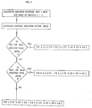
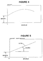
- the vehicle related constants may be determined graphically by plotting for each of the sets of values SVn the curve of SETUPQOT against the actual setup lateral acceleration SETUPLAT and then taking the values of the vehicle related constants A and E to be equal to the intercepts of the curve on the SETUPQOT axis for the clockwise and anti-clockwise data respectively and then plotting graphically for each set of values SVn the quotient of (SETUPQOT - A) or (SETUPQOT - E) divided by SETUPLATn against SETUPLAT, drawing the best straight line through the graphical points according to a suitable method and then taking the vehicle related constants B and F to be equal to the intercept of the best straight line on the (SETUPQOT-A) or (SETUPQOT-E) axis and taking the vehicle related constants C and G to be equal to the slope of the best straight line for the clockwise and anti-clockwise data respectively.
- the best straight line may be drawn through the data points by the Method of Least Squares.
- the tyre warning indicator is operated when the magnitude of the corrected error value is in the range 0.05 to 0.2.
- the centralising constant used in the derivation of the central deciding factor MPSD may be in the range of 0.250125 to 0.250625 and preferably has a value of 0.25025.
- FAC(W) DEL'FAC(W)/DEL'FAC(1) and if the value of the corrected error value DEL divided by the wheel factor FAC(W) for the wheel having numerically the greater deflation indicating factor (IMC1-IMC4) is in the range 0.05 to 0.5 then operating a tyre warning indicator provided in the vehicle to indicate that wheel has a deflated tyre.
- an initialisation procedure may be carried out. This monitors the signals under normal driving conditions and enables constants for each wheel to be determined to allow for variations.
- the apparatus shown in Figure 1 provides a deflation warning device for a vehicle having four wheels 1, 2, 3 and 4.
- Wheels 1 and 2 are the left- and right-hand front wheels respectively and wheels 3 and 4 are the left- and right-hand rear wheels respectively.
- Each wheel has a toothed wheel device associated with it of the type designed and fitted to provide a digital signal comprising a magnetic pick-up of the type used for a vehicle anti-skid system of the electronic type - often commonly known as ABS braking system.
- Each pick-up is additionally connected in this case to a deflation warning detection system which uses the same digital signal as the ABS system.
- the electronic signals from each of the four wheels are carried through cables 5 to four separate inputs 6, 7, 8 and 9 of a central processing unit 10.
- Four separate indicator lights 12, 13, 14 and 15 are provided one for each wheel 1, 2, 3 and 4. These indicator lights may be most conveniently mounted on the vehicle dashboard.
- the central processing unit 10 is basically a microprocessor which monitors the four signals and compares them to determine if an outward signal is to be sent to operate an indicator light to warn of a deflated tyre.
- the microprocessor 10 may be the same microprocessor as the ABS system. Alternatively a separate microprocessor may be provided.
- the respective values of the total digital pulse signals from each of the wheels 1, 2, 3 and 4 in a five second period are C1, C2, C3 and C4 respectively.
- the central processing unit 10 computes these frequency values as will be described below to determine whether or not to send a deflation warning signal to one of the warning lights 12, 13, 14 or 15.
- Speeds which have been used start at 20kph and increase in intervals of 5kph, i.e. SV1 is measured at 20kph and SVn is measured at 20 + (5 x (n-1))kph.
- the next step is then to plot graphically for each set of values SVn the quotient of (SETUPQOT - A) or (SETUPQOT - E) divided by SETUPLATn against SETUPLATn. This is shown in Figure 5.
- the method then proceeds by drawing the best straight line (BSTRL) through the graphical points according to the method of least squares or any other suitable method and then taking the vehicle related constants B and F to be equal to the intercept (INTCPT2) of the best straight line on the (SETUPQOT-A) or (SETUPQOT-E) axis and taking the vehicle related constant C and G to be equal to the slope (SLOPE2) of the best straight line for the clockwise and anti-clockwise data respectively.
- a detailed description of the method of least squares can be seen for example in "Statistics for Technologists", Chapter X, Paradine and Rivett, first published 1953 by English Universities Press Limited, London.
- the values of the vehicle related constants may be determined mathematically.
- One such method is by deriving curvilinear regression equation relating SETUPDEL to SETUPLAT and setting the pairs of constants A and E, B and F, and c and G equal to respectively the coefficients of the linear, square and cubic terms in SETUPLAT for the clockwise and anti-clockwise data respectively.
- Another such method is by deriving the curvilinear regression equation of SETUPQOT on SETUPLAT and then setting the pairs of constants A and E, B and f, and C and G equal to respectively the constant term and the coefficients of the linear and squared terms in SETUPLAT for the clockwise and anticlockwise data respectively.
- DEL' [(C1+C4)/2-(C2+C3)/2] (C1 + C2 + C3 + C4)/4 x 100
- the actual wheel speed values may be distorted due to vehicle factors such as cornering, braking, accelerating or uneven loads which give rise to a greater effect than that caused by a tyre deflation it is necessary to correct this calculated error value to remove these vehicle effects.
- a correction factor LAT is calculated according to the magnitude of respective deciding factors MC1-MC4 for each wheel in comparison to a central deciding factor MPSD.
- the central deciding factor is equal to the sum for the four deciding factors MC1-MC2 multiplied by a centralising constant K which in this embodiment is selected to be 0.25025.
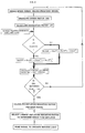
- the central processing unit 10 decides if the value of DEL is in the range of 0.05 to 0.5 which indicates the presence of a deflated tyre.
- Values of DEL below 0.05 are the result of minor statistical variation in the counts from each wheel whereas values of DEL greater than 0.5 indicate a relatively uncommon occurrence such as wheel spin or a locked wheel and are greater than the effect of a punctured tyre.
- the central processing unit 10 finds that the corrected error value is between 0.05 and 0.5 then the method of the invention moves on to the next stage which is to determine which tyre is deflated. Otherwise the system continues to monitor wheel speeds.
- the central processing unit compares these to determine which wheel has the factor of the largest magnitude.
- a signal is then sent to operate the indicator light corresponding to that wheel in order to alert the driver that the tyre concerned has deflated.
- the warning signal is only sent after three sets of deflation indicating factors, calculated from successive sets of wheel speed data, all indicate that a particular tyre is deflated.
- the corrected error factor DEL is further corrected for differences between each of the four wheels 1-4 by dividing its value by a wheel factor FAC(1)-FAC(4) for the particular wheel which is indicated as having a deflated tyre.
- the tyre warning indicator provided in the vehicle is operated to indicate that the particular wheel has a deflated tyre.
- the above embodiment has illustrated the method of the invention using the signal data from a multi-toothed wheel system typically producing 48 or 96 pulses per wheel revolution
- the invention can equally be used with other wheel speed sensing systems.
- the method may be used with a simple system which uses a single pulse per revolution to compute the time period for one rotation of each wheel, in which case it will be necessary to multiply the wheel speeds by a constant factor to obtain data in the necessary form.
Applications Claiming Priority (2)
| Application Number | Priority Date | Filing Date | Title |
|---|---|---|---|
| GB9320821 | 1993-10-09 | ||
| GB939320821A GB9320821D0 (en) | 1993-10-09 | 1993-10-09 | Method of setecting a deflated tyre on a vehicle |
Publications (2)
| Publication Number | Publication Date |
|---|---|
| EP0647535A1 true EP0647535A1 (de) | 1995-04-12 |
| EP0647535B1 EP0647535B1 (de) | 1997-03-19 |
Family
ID=10743252
Family Applications (1)
| Application Number | Title | Priority Date | Filing Date |
|---|---|---|---|
| EP94307340A Expired - Lifetime EP0647535B1 (de) | 1993-10-09 | 1994-10-06 | Verfahren zum Erkennen eines leeren Reifens an einem Fahrzeug |
Country Status (7)
| Country | Link |
|---|---|
| US (1) | US5552760A (de) |
| EP (1) | EP0647535B1 (de) |
| JP (1) | JP3095956B2 (de) |
| KR (1) | KR100306445B1 (de) |
| DE (1) | DE69402146T2 (de) |
| GB (1) | GB9320821D0 (de) |
| TW (1) | TW287989B (de) |
Cited By (1)
| Publication number | Priority date | Publication date | Assignee | Title |
|---|---|---|---|---|
| US6137400A (en) * | 1997-08-22 | 2000-10-24 | Sumitomo Rubber Industries, Ltd. | Apparatus and method for detecting decrease in tire air-pressure |
Families Citing this family (16)
| Publication number | Priority date | Publication date | Assignee | Title |
|---|---|---|---|---|
| GB9504217D0 (en) * | 1995-03-02 | 1995-04-19 | Sumitomo Rubber Ind | A method of determining the inflation pressure of a tyre on a moving vehicle |
| JP3509331B2 (ja) * | 1995-10-11 | 2004-03-22 | 本田技研工業株式会社 | 車両の車輪減圧判定装置 |
| US5721528A (en) * | 1996-12-23 | 1998-02-24 | Ford Global Technologies, Inc. | Low tire warning system |
| US5801556A (en) * | 1997-02-11 | 1998-09-01 | Hughes Electronics | Low voltage CMOS FPA interface |
| JPH1159148A (ja) | 1997-08-12 | 1999-03-02 | Sumitomo Rubber Ind Ltd | タイヤ空気圧異常警報装置および方法 |
| US6339957B1 (en) | 1998-07-09 | 2002-01-22 | Sumitomo Rubber Industries, Ltd. | Apparatus for identifying tires and method thereof |
| KR100689411B1 (ko) * | 2000-03-17 | 2007-03-08 | 베루 악티엔게젤샤프트 | 송신기가 설치된 바퀴에, 타이어 공기압 감시 시스템에 있는 송신기에서 구한 신호에 함유된 식별자를 할당하는 방법 |
| US6222444B1 (en) | 2000-04-03 | 2001-04-24 | Robert Bosch Corporation | Method for detecting a deflated tire on a vehicle |
| JP4534072B2 (ja) | 2000-04-11 | 2010-09-01 | 住友ゴム工業株式会社 | タイヤ空気圧低下警報装置および方法、ならびにタイヤの内圧低下判定消去プログラム |
| US6285280B1 (en) | 2000-06-26 | 2001-09-04 | Robert Bosch Corporation | Method for detecting a deflated tire on a vehicle |
| JP3561213B2 (ja) | 2000-07-18 | 2004-09-02 | 住友ゴム工業株式会社 | タイヤ空気圧低下警報装置および方法 |
| US6459369B1 (en) | 2000-11-22 | 2002-10-01 | Robert Bosch Corporation | Tire deflation detection system with feedback component |
| JP4171174B2 (ja) * | 2000-12-14 | 2008-10-22 | 住友ゴム工業株式会社 | タイヤ識別装置および方法 |
| DE60144364D1 (de) | 2000-12-14 | 2011-05-19 | Sumitomo Rubber Ind | Vorrichtung und Verfahren zur Reifenidentifizierung sowie Vorrichtung und Verfahren zur Fahrbahnzustandsauswertung |
| JP2007147520A (ja) * | 2005-11-29 | 2007-06-14 | Toyota Motor Corp | 車輪状態推定装置および車両制御装置 |
| CN104709002B (zh) * | 2013-12-13 | 2017-02-15 | 北汽福田汽车股份有限公司 | 胎压报警方法、胎压报警装置和车辆 |
Citations (5)
| Publication number | Priority date | Publication date | Assignee | Title |
|---|---|---|---|---|
| EP0489562A1 (de) * | 1990-12-06 | 1992-06-10 | Sumitomo Rubber Industries Limited | Verfahren zur Feststellung eines leeren Reifens an einem Fahrzeug |
| EP0497120A1 (de) * | 1991-01-31 | 1992-08-05 | TEMIC TELEFUNKEN microelectronic GmbH | System zur Luftdruckkontrolle von Kfz-Reifen |
| EP0552827A1 (de) * | 1992-01-21 | 1993-07-28 | General Motors Corporation | Reifendrücküberwachungssystem |
| EP0564285A1 (de) * | 1992-04-02 | 1993-10-06 | Sumitomo Rubber Industries Limited | Verfahren zum Erkennen eines leeren Reifens an einem Fahrzeug |
| EP0607690A1 (de) * | 1992-12-21 | 1994-07-27 | Sumitomo Rubber Industries Limited | Verfahren und Vorrichtung zur Erkennen von Reifenfehlern |
Family Cites Families (5)
| Publication number | Priority date | Publication date | Assignee | Title |
|---|---|---|---|---|
| GB8711310D0 (en) * | 1987-05-13 | 1987-06-17 | Sp Tyres Uk Ltd | Tyres deflation warning device |
| GB9002925D0 (en) * | 1990-02-09 | 1990-04-04 | Sumitomo Rubber Ind | Method of detecting a deflated tyre on a vehicle |
| GB9002924D0 (en) * | 1990-02-09 | 1990-04-04 | Sumitomo Rubber Ind | Method of detecting a delfated tyre on a vehicle |
| GB9026558D0 (en) * | 1990-12-06 | 1991-01-23 | Sumitomo Rubber Ind | Method of detecting a deflated tyre on a vehicle |
| GB9109466D0 (en) * | 1991-05-02 | 1991-06-26 | Sumitomo Rubber Ind | A method of detecting a deflated tyre on a vehicle |
-
1993
- 1993-10-09 GB GB939320821A patent/GB9320821D0/en active Pending
-
1994
- 1994-10-01 TW TW083109085A patent/TW287989B/zh not_active IP Right Cessation
- 1994-10-03 US US08/316,488 patent/US5552760A/en not_active Expired - Lifetime
- 1994-10-05 JP JP06241322A patent/JP3095956B2/ja not_active Expired - Lifetime
- 1994-10-06 EP EP94307340A patent/EP0647535B1/de not_active Expired - Lifetime
- 1994-10-06 DE DE69402146T patent/DE69402146T2/de not_active Expired - Lifetime
- 1994-10-07 KR KR1019940025678A patent/KR100306445B1/ko not_active IP Right Cessation
Patent Citations (5)
| Publication number | Priority date | Publication date | Assignee | Title |
|---|---|---|---|---|
| EP0489562A1 (de) * | 1990-12-06 | 1992-06-10 | Sumitomo Rubber Industries Limited | Verfahren zur Feststellung eines leeren Reifens an einem Fahrzeug |
| EP0497120A1 (de) * | 1991-01-31 | 1992-08-05 | TEMIC TELEFUNKEN microelectronic GmbH | System zur Luftdruckkontrolle von Kfz-Reifen |
| EP0552827A1 (de) * | 1992-01-21 | 1993-07-28 | General Motors Corporation | Reifendrücküberwachungssystem |
| EP0564285A1 (de) * | 1992-04-02 | 1993-10-06 | Sumitomo Rubber Industries Limited | Verfahren zum Erkennen eines leeren Reifens an einem Fahrzeug |
| EP0607690A1 (de) * | 1992-12-21 | 1994-07-27 | Sumitomo Rubber Industries Limited | Verfahren und Vorrichtung zur Erkennen von Reifenfehlern |
Cited By (1)
| Publication number | Priority date | Publication date | Assignee | Title |
|---|---|---|---|---|
| US6137400A (en) * | 1997-08-22 | 2000-10-24 | Sumitomo Rubber Industries, Ltd. | Apparatus and method for detecting decrease in tire air-pressure |
Also Published As
| Publication number | Publication date |
|---|---|
| KR950011153A (ko) | 1995-05-15 |
| DE69402146D1 (de) | 1997-04-24 |
| EP0647535B1 (de) | 1997-03-19 |
| JP3095956B2 (ja) | 2000-10-10 |
| US5552760A (en) | 1996-09-03 |
| GB9320821D0 (en) | 1993-12-01 |
| KR100306445B1 (ko) | 2002-04-06 |
| JPH07149119A (ja) | 1995-06-13 |
| DE69402146T2 (de) | 1997-06-26 |
| TW287989B (de) | 1996-10-11 |
Similar Documents
| Publication | Publication Date | Title |
|---|---|---|
| EP0564285B1 (de) | Verfahren zum Erkennen eines leeren Reifens an einem Fahrzeug | |
| EP0647536B1 (de) | Verfahren zum Erkennen eines leeren Reifens an einem Fahrzeug | |
| EP0647535B1 (de) | Verfahren zum Erkennen eines leeren Reifens an einem Fahrzeug | |
| EP0489562B1 (de) | Verfahren zur Feststellung eines leeren Reifens an einem Fahrzeug | |
| EP0512745B1 (de) | Verfahren zum Erkennen eines leeren Reifens an einem Fahrzeug | |
| EP0489563B1 (de) | Verfahren zur Feststellung eines leeren Reifens an einem Fahrzeug | |
| EP1167086B1 (de) | Gerät und Verfahren zum Detektieren eines Druckabfalls im Reifen | |
| EP0908331B1 (de) | Gerät und Verfahren zum Detektieren eines Druckabfalles im Reifen | |
| US5589816A (en) | Method and device for detecting a deflated tire on a vehicle | |
| US6501373B2 (en) | Apparatus and method for alarming decrease in tire air-pressure | |
| EP0579446B1 (de) | Verfahren zum Erkennen eines leeren Reifens an einem Fahrzeug | |
| EP0787606B1 (de) | Verfahren zum Erkennen eines platten Reifens an einem Fahrzeug | |
| JP3626076B2 (ja) | タイヤ空気圧低下警報装置および方法 | |
| JPH06166308A (ja) | 車両に装着されたタイヤの減圧検出方法 | |
| JPH06286428A (ja) | 車両に装着されたタイヤの減圧検出方法 |
Legal Events
| Date | Code | Title | Description |
|---|---|---|---|
| PUAI | Public reference made under article 153(3) epc to a published international application that has entered the european phase |
Free format text: ORIGINAL CODE: 0009012 |
|
| AK | Designated contracting states |
Kind code of ref document: A1 Designated state(s): DE FR GB |
|
| 17P | Request for examination filed |
Effective date: 19950502 |
|
| GRAG | Despatch of communication of intention to grant |
Free format text: ORIGINAL CODE: EPIDOS AGRA |
|
| GRAH | Despatch of communication of intention to grant a patent |
Free format text: ORIGINAL CODE: EPIDOS IGRA |
|
| 17Q | First examination report despatched |
Effective date: 19960801 |
|
| GRAH | Despatch of communication of intention to grant a patent |
Free format text: ORIGINAL CODE: EPIDOS IGRA |
|
| GRAA | (expected) grant |
Free format text: ORIGINAL CODE: 0009210 |
|
| AK | Designated contracting states |
Kind code of ref document: B1 Designated state(s): DE FR GB |
|
| REF | Corresponds to: |
Ref document number: 69402146 Country of ref document: DE Date of ref document: 19970424 |
|
| ET | Fr: translation filed | ||
| PLBE | No opposition filed within time limit |
Free format text: ORIGINAL CODE: 0009261 |
|
| STAA | Information on the status of an ep patent application or granted ep patent |
Free format text: STATUS: NO OPPOSITION FILED WITHIN TIME LIMIT |
|
| 26N | No opposition filed | ||
| REG | Reference to a national code |
Ref country code: GB Ref legal event code: IF02 |
|
| PGFP | Annual fee paid to national office [announced via postgrant information from national office to epo] |
Ref country code: GB Payment date: 20131002 Year of fee payment: 20 Ref country code: DE Payment date: 20131002 Year of fee payment: 20 Ref country code: FR Payment date: 20131009 Year of fee payment: 20 |
|
| REG | Reference to a national code |
Ref country code: DE Ref legal event code: R071 Ref document number: 69402146 Country of ref document: DE |
|
| REG | Reference to a national code |
Ref country code: DE Ref legal event code: R071 Ref document number: 69402146 Country of ref document: DE |
|
| REG | Reference to a national code |
Ref country code: GB Ref legal event code: PE20 Expiry date: 20141005 |
|
| PG25 | Lapsed in a contracting state [announced via postgrant information from national office to epo] |
Ref country code: GB Free format text: LAPSE BECAUSE OF EXPIRATION OF PROTECTION Effective date: 20141005 |