EP0647476A1 - Construction de parois pour une cabine d'une installation de peinture - Google Patents
Construction de parois pour une cabine d'une installation de peinture Download PDFInfo
- Publication number
- EP0647476A1 EP0647476A1 EP94114468A EP94114468A EP0647476A1 EP 0647476 A1 EP0647476 A1 EP 0647476A1 EP 94114468 A EP94114468 A EP 94114468A EP 94114468 A EP94114468 A EP 94114468A EP 0647476 A1 EP0647476 A1 EP 0647476A1
- Authority
- EP
- European Patent Office
- Prior art keywords
- wall construction
- construction according
- wall
- cabin
- framework
- Prior art date
- Legal status (The legal status is an assumption and is not a legal conclusion. Google has not performed a legal analysis and makes no representation as to the accuracy of the status listed.)
- Withdrawn
Links
Images


Classifications
-
- B—PERFORMING OPERATIONS; TRANSPORTING
- B05—SPRAYING OR ATOMISING IN GENERAL; APPLYING FLUENT MATERIALS TO SURFACES, IN GENERAL
- B05B—SPRAYING APPARATUS; ATOMISING APPARATUS; NOZZLES
- B05B16/00—Spray booths
- B05B16/40—Construction elements specially adapted therefor, e.g. floors, walls or ceilings
Definitions
- the invention relates to a wall construction for a side wall or the side walls of a cabin of a painting system, in particular a system for painting vehicle bodies.
- B. can be a cabin in which a painting process takes place, but also another cabin of a painting system, such as. B. the so-called preparation zone, in which the objects to be painted are cleaned.
- the invention is concerned with the design of the cabin side walls in the area which lies between a so-called filter ceiling which delimits the cabin space upwards and a cabin floor which delimits the cabin space downwards, the latter usually having the shape of a grating floor.
- a known such wall construction as described and shown in DE-A-35 10 860, consists essentially of vertical supports arranged at a distance from one another in the longitudinal direction of the cabin and components arranged between them and fastened to the supports, each of which is formed by profiled strips Has frame and a tabular wall element held by the latter.
- the vertical supports and the profile strips that form the frames are extruded aluminum profile strips, and the panel-shaped wall elements are glass plates and plates made of aluminum or stainless steel sheet.
- the tabular wall elements are held in circumferential grooves formed by the profile frame, and the supports and the components located between them and fastened to the supports are arranged in such a way that the wall construction forms a substantially smooth surface on its side facing the interior of the cabin, apart from the fact that at the transition from the tabular wall elements to the profile strips holding them. Frame due to the type of mounting of the tabular wall elements, one step each.
- the invention had for its object to provide such a wall structure, which includes vertical supports and tabular wall elements, which can be produced more cost-effectively than the known wall construction described above, and to solve this problem, the invention proposes to design the wall construction in such a way that the vertical supports together with attached to them, in the vertical direction at a distance from each other form a load-bearing frame truss, the supports and cross struts form compartments closed by a panel-shaped wall element in such a way that the frame truss is covered on its side facing the cabin interior by the panel-shaped wall elements and that the wall elements have plates made of a material which is more corrosion-resistant than the material of the framework.
- the parts of the framework that is to say its supports and cross struts, can be produced inexpensively from relatively inexpensive material, in particular from normal steel, since they are covered by the tabular wall elements to the interior of the cabin, so that it is sufficient if more expensive for the latter Materials such as glass, stainless steel and aluminum can be used.
- the invention therefore opens up a further possibility to save costs by designing the framework truss alone as a load-bearing part of the wall construction, which enables savings in the more expensive materials for the panel-shaped wall elements.
- the latter can be frameless, as is the case with preferred embodiments of the invention.
- the supporting function is taken over alone or at least essentially by the framework, a completely flat surface can be brought about on the side of the wall construction facing the cabin in a simple manner by placing the glass plates in the compartments formed by the framework be glued and sheet metal wall elements formed by sheet metal are screwed or welded to the framework, because then, with a corresponding arrangement of the plate wall elements, those steps can be avoided which are unavoidable in the known wall construction described above at the transition of the plate wall elements to the profile strip frames holding them are.
- the glass plates are held by metallic holding elements which are detachably fastened to the framework, so that the adhesive or sealing compound only has to serve the purpose of producing as smooth, seamless and flat a surface as possible on the side of the wall construction facing the cabin .
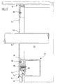
- Fig. 1 shows a part of a filter cover 10, the z. B. a paint spray booth limited upwards, wherein the part of the filter cover 10 shown in FIG. 1 is formed by two filter ceiling elements 12 and 14. 1 also shows two modules 16 and 18 of a cabin side wall with a wall construction according to the invention. The interior of the cabin is therefore under the filter ceiling 10 and to the left of or behind the wall modules 16 and 18.
- FIG. 1 there is a second painting system on the right in front of the painting system to which the parts shown in FIG. 1 belong, the two painting systems being arranged parallel to one another and at a transverse distance from one another and between them a so-called cleanroom is located, which is bounded at the top by a cleanroom ceiling 20, of which FIG. 1 only shows a ceiling element.
- the framework consisting of two vertical supports 22 and 24 and cross struts 26, 28, 30, 32 and 34, the ends of which are fastened to the supports 22 and 24, for example by screws or by welding, so that these elements form a load-bearing framework form.
- the supports as well as the cross struts are designed according to the invention as metallic hollow profiles and consist in particular of normal steel.
- the supports 22 and 24 are designed as cable ducts and have large openings 36 and 38, which can be closed by covers 40 and 42 shown in the released and lifted-off state in FIG. 1, so that the cable ducts are easily accessible can be.
- connection profile 44 obtained from a bent sheet metal strip is fastened, in particular by welding, on which the cleanroom ceiling 20 can be placed; In this way it is possible to connect the cleanroom ceiling in a dust-tight manner to the cabin side wall constructions of two adjacent painting systems.
- FIG. 1 shows on the basis of the wall module 16 one of the various possibilities for the infill of the frame framework of the wall construction according to the invention with different panel-shaped wall elements.
- a glass plate 46 between the cross struts 26 and 28 there is a glass plate 46 between the cross struts 26 and 28, a sheet metal plate 48 between the cross struts 28 and 30, a glass plate 50 between the cross struts 30 and 32 and a sheet metal plate 52 again between the cross struts 32 and 34.
- the sheet metal plates 48 and 52 can be plates made of aluminum sheet or stainless steel sheet.
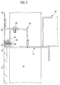
- FIGS. 1 and 2 show that, according to the invention, the uppermost cross struts 26 are arranged at a distance below the filter ceiling 10 and the connection of the wall modules of the wall construction according to the invention to the filter ceiling 10 takes place by means of a plate-shaped wall element, which in the preferred embodiment of the wall construction according to the invention shown is an installation plate 54 made of a corrosion-resistant material, in particular made of aluminum plate or stainless steel plate, which is firmly connected on the one hand to the cross strut and on the other hand to the filter ceiling 10 .
- a construction is preferred in which such an installation plate 54 is assigned to each wall module, so that the upper connection of the wall modules to the filter ceiling is made by a series of such installation plates.
- a further metallic hollow profile strip 56 is welded to the metallic hollow profile forming the cross strut 26, which in particular is a profile strip made of normal steel and to which the installation plate 54 is fastened by means of screws 58.
- the connection of the installation plate 54 to the filter cover 10 by means of screws 60 can be seen in the fact that they can be easily removed at any time to carry out subsequent installations, for. B. the introduction of a carbon dioxide line 62 indicated in FIG. 2 as part of a fire extinguishing system. It is particularly advantageous that through openings 64 for such subsequent installations do not have to be made in the installed state of the installation plates 54, but can be produced on the removed installation plates.
- FIG. 2 also shows in detail how the glass plate 46 adjoining the installation plate 54 downward is held on the framework truss according to the invention.
- a metallic profile retaining strip on the cross strut 26 66 fastened by means of screws 68, which has a retaining groove 70 for engaging the upper edge of the glass plate 46.
- screws 68 When the screws 68 are tightened, the glass plate 46 is pressed against an elastic sealing strip 72 which has been inserted between the glass plate and the cross strut 26.
- the upper edge of the glass plate 46 is covered by the lower edge region of the installation plate 54.
- a step 74 between the glass plate 46 and the lower edge of the installation plate 54 represents the only unevenness on the side of the wall construction according to the invention facing the cabin interior.
- FIG 3 shows, in addition to the connection of the cleanroom ceiling 20 to the wall construction according to the invention, particularly advantageous designs of the planking according to the invention on the side of the framework of the wall construction according to the invention facing the cabin interior.
- the sheet metal plate 48 overlaps the side of the cross strut 30 facing the interior of the cabin and is connected to the latter by means of a screw connection;
- a bracket 80 is welded to the sheet metal plate 48, which is fastened to the cross strut 30 by means of screws 82.
- the sheet metal plate 48 bears with a bent lower edge 84 against the cross strut 30, and below this bent edge, in particular at a distance from it, a metallic profile holding strip 86 is fastened to the cross strut 30 by means of screws 88.
- the latter has a holding groove 90 for holding the upper edge of the glass plate designed according to the invention as a laminated glass pane 50, wherein the retaining groove 90 and the edge of the glass plate are designed in cross section so that the glass plate cannot fall out of the frame framework even in the event of fire.
- the area between the lower edge of the sheet metal plate 48 and the upper edge of the glass plate 50 is filled with a sealing compound 92 such that a flat surface is obtained on the side of the wall construction according to the invention facing the cabin interior.
- the sealing compound 92 is preferably a possibly similarly temperature-resistant adhesive-like compound.
- connection profile 44 welded to the cross strut 30 has been omitted in order to clarify that plate-shaped wall elements of the wall construction according to the invention, which are designed as glass plates or sheet metal plates, are fastened to the framework truss in the same way everywhere, as can be seen from the installation plates 54 designed wall elements that accomplish the connection of the wall construction according to the invention to the filter ceiling 10. Therefore, elements used in FIG. 4 for connecting the sheet metal plate 52 and the glass plate 50 to the cross strut 32 have been given the same reference numerals as the elements shown in FIG. 3 and used to connect the sheet metal plate 48 and the glass plate 50 to the cross strut 30.
- a support structure 100 which carries a grating floor 102 of the cabin and between which and the cross strut 34 and the sheet metal plate 52 sealing cords 104 and 106 are inserted. Joints resulting on both sides of these sealing cords were in turn sealed with the sealing compound 92.
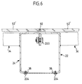
- FIG. 6 now shows how, according to the invention, the mutually adjacent supports of two wall modules which follow one another in the longitudinal direction of the cabin are connected to one another and connect the tabular wall elements of these modules to one another in the region of this connection.
- the two plate-shaped wall elements shown in FIG. 6 would be sheet metal plates 52, but to clarify that the sheet metal plates and the glass plates can be interchanged, 6 shows two glass plates 52 'designed as laminated glass panes.
- FIG. 6 shows how the cross struts, here the cross struts 34, are connected at their ends to the supports 22, 24 by welding.
- the lateral edges of the tabular wall elements here the glass plates 52 ', of mutually adjacent wall modules butt against one another, the joint formed in this way being filled with the sealing compound 92.
- the tabular wall elements in the case of FIG. 6 the glass plates 52 ', thus also form a completely flat surface in this area on the side of the wall construction according to the invention facing the cabin interior.
- the framework can also be paneled with tabular wall elements, in the lower area of the wall construction installation cabinets or the like can be attached to the outside thereof, and in addition the above description shows that there are all tabular wall elements are arranged on the side of the wall construction according to the invention facing the interior of the cabin, can also be of the same kind of tabular wall elements, d. H. in all cases around glass plates or sheet metal plates.
- the plates can also be fastened according to the invention directly to the supports and cross struts using screws; it is only necessary to provide holes in the plates for the screws to be inserted. These holes are preferably provided with a countersink so that countersunk screws can be used to obtain a completely flat surface on the side of the wall construction facing the cabin interior.
Applications Claiming Priority (2)
| Application Number | Priority Date | Filing Date | Title |
|---|---|---|---|
| DE4334043 | 1993-10-06 | ||
| DE4334043A DE4334043A1 (de) | 1993-10-06 | 1993-10-06 | Wandkonstruktion für eine Kabine einer Lackieranlage |
Publications (1)
| Publication Number | Publication Date |
|---|---|
| EP0647476A1 true EP0647476A1 (fr) | 1995-04-12 |
Family
ID=6499530
Family Applications (1)
| Application Number | Title | Priority Date | Filing Date |
|---|---|---|---|
| EP94114468A Withdrawn EP0647476A1 (fr) | 1993-10-06 | 1994-09-14 | Construction de parois pour une cabine d'une installation de peinture |
Country Status (2)
| Country | Link |
|---|---|
| EP (1) | EP0647476A1 (fr) |
| DE (1) | DE4334043A1 (fr) |
Cited By (4)
| Publication number | Priority date | Publication date | Assignee | Title |
|---|---|---|---|---|
| WO1999012657A1 (fr) | 1997-09-10 | 1999-03-18 | Eisenmann Maschinenbau Kg | Paroi de cabine pour chaine de vernissage |
| WO1999012656A1 (fr) | 1997-09-10 | 1999-03-18 | Eisenmann Maschinenbau Kg | Paroi de cabine pour chaine de vernissage |
| DE102006052854A1 (de) * | 2006-11-09 | 2008-05-21 | Eisenmann Anlagenbau Gmbh & Co. Kg | Großraumkabine zur Behandlung, insbesondere zum Spritzen und/oder Trocknen, von Werkstücken |
| CN109127247A (zh) * | 2018-10-25 | 2019-01-04 | 中汽(天津)系统工程有限公司 | 一种汽车涂装生产线模锻化工作室体结构 |
Families Citing this family (2)
| Publication number | Priority date | Publication date | Assignee | Title |
|---|---|---|---|---|
| DE102007063162B3 (de) * | 2007-12-19 | 2009-03-05 | Karl-Heinz Fehr | Modulartig zusammengesetzte Beschichtungszelle |
| DE102017119129A1 (de) * | 2017-08-22 | 2019-02-28 | Eisenmann Se | Produktionsanlage zur Behandlung von Werkstücken |
Citations (3)
| Publication number | Priority date | Publication date | Assignee | Title |
|---|---|---|---|---|
| AT368037B (de) * | 1981-01-12 | 1982-08-25 | Unitherm Oesterreich Gmbh | Spritzlackier- und trockenkabine |
| FR2635801A1 (fr) * | 1988-08-30 | 1990-03-02 | Timo Ind | Cloisons fabriquees par assemblage de panneaux et de vitres |
| DE9306821U1 (fr) * | 1993-05-06 | 1993-07-15 | Eisenmann Maschinenbau Kg (Komplementaer: Eisenmann-Stiftung), 7030 Boeblingen, De |
Family Cites Families (2)
| Publication number | Priority date | Publication date | Assignee | Title |
|---|---|---|---|---|
| DE3510860A1 (de) * | 1985-03-26 | 1986-10-09 | Dürr GmbH, 7000 Stuttgart | Kabinenkonstruktion |
| DE4227889A1 (de) * | 1992-08-22 | 1994-02-24 | Goetz Metall Anlagen | Lackierkabine |
-
1993
- 1993-10-06 DE DE4334043A patent/DE4334043A1/de not_active Withdrawn
-
1994
- 1994-09-14 EP EP94114468A patent/EP0647476A1/fr not_active Withdrawn
Patent Citations (3)
| Publication number | Priority date | Publication date | Assignee | Title |
|---|---|---|---|---|
| AT368037B (de) * | 1981-01-12 | 1982-08-25 | Unitherm Oesterreich Gmbh | Spritzlackier- und trockenkabine |
| FR2635801A1 (fr) * | 1988-08-30 | 1990-03-02 | Timo Ind | Cloisons fabriquees par assemblage de panneaux et de vitres |
| DE9306821U1 (fr) * | 1993-05-06 | 1993-07-15 | Eisenmann Maschinenbau Kg (Komplementaer: Eisenmann-Stiftung), 7030 Boeblingen, De |
Cited By (13)
| Publication number | Priority date | Publication date | Assignee | Title |
|---|---|---|---|---|
| WO1999012657A1 (fr) | 1997-09-10 | 1999-03-18 | Eisenmann Maschinenbau Kg | Paroi de cabine pour chaine de vernissage |
| WO1999012656A1 (fr) | 1997-09-10 | 1999-03-18 | Eisenmann Maschinenbau Kg | Paroi de cabine pour chaine de vernissage |
| DE19739642A1 (de) * | 1997-09-10 | 1999-03-25 | Eisenmann Kg Maschbau | Wand für die Kabine einer Lackieranlage |
| DE19739644A1 (de) * | 1997-09-10 | 1999-03-25 | Eisenmann Kg Maschbau | Wand für die Kabine einer Lackieranlage |
| DE19739644C2 (de) * | 1997-09-10 | 1999-08-05 | Eisenmann Kg Maschbau | Wand für die Kabine einer Lackieranlage |
| DE19739642C2 (de) * | 1997-09-10 | 1999-12-16 | Eisenmann Kg Maschbau | Wand für die Kabine einer Lackieranlage |
| US6230470B1 (en) | 1997-09-10 | 2001-05-15 | Eisenmann Maschinenbau Kg | Wall for the booth of a coating plant |
| DE102006052854A1 (de) * | 2006-11-09 | 2008-05-21 | Eisenmann Anlagenbau Gmbh & Co. Kg | Großraumkabine zur Behandlung, insbesondere zum Spritzen und/oder Trocknen, von Werkstücken |
| US8156689B2 (en) | 2006-11-09 | 2012-04-17 | Eisenmann Ag | Large-capacity booth for the treatment, in particular the spraying and/or drying, of workpieces |
| DE102006052854B4 (de) * | 2006-11-09 | 2012-05-10 | Eisenmann Ag | Großraumkabine zur Behandlung von Werkstücken |
| EP1921230A3 (fr) * | 2006-11-09 | 2013-07-31 | Eisenmann AG | Cabine de grande taille pour le traitement, en particulier pour la pulvérisation et/ou le séchage de pièces à usiner |
| CN109127247A (zh) * | 2018-10-25 | 2019-01-04 | 中汽(天津)系统工程有限公司 | 一种汽车涂装生产线模锻化工作室体结构 |
| CN109127247B (zh) * | 2018-10-25 | 2024-04-09 | 中汽(天津)系统工程有限公司 | 一种汽车涂装生产线模锻化工作室体结构 |
Also Published As
| Publication number | Publication date |
|---|---|
| DE4334043A1 (de) | 1995-04-20 |
Similar Documents
| Publication | Publication Date | Title |
|---|---|---|
| DE3810268C2 (fr) | ||
| EP0608761B1 (fr) | Structure de caisse de voiture, notamment ferroviaire | |
| EP0236291B1 (fr) | Poutre protectrice en particulier pour le renforcement des portières de véhicule automobile | |
| DE2936866A1 (de) | Karosserie fuer ein fahrzeug und mit dieser karosserie ausgestattetes fahrzeug | |
| DE3920353A1 (de) | Geruest fuer einen schaltschrank aus mehrfach abgewinkelten profilelementen mit einseitig offenem hohlprofil | |
| DE102006052854B4 (de) | Großraumkabine zur Behandlung von Werkstücken | |
| EP0964807B1 (fr) | Cadre pour fixer des elements plats | |
| EP1285837B1 (fr) | Ossature d' une caisse de véhicule | |
| EP0185188B1 (fr) | Cabine | |
| EP0647476A1 (fr) | Construction de parois pour une cabine d'une installation de peinture | |
| EP1798186A1 (fr) | Cabine d'ascenseur et méthode de montage de panneaux d'une parroi de cabine | |
| EP0298328B1 (fr) | Mur de façade | |
| EP4039904A1 (fr) | Salle blanche | |
| EP0791528A2 (fr) | Structure de caisse pour un véhicule utilitaire notamment un véhicule d'intervention comme un fourgon de pompiers | |
| AT501334A1 (de) | Rahmenkonstruktion | |
| DE102013216821B4 (de) | Karosseriestruktur für ein Fahrzeug | |
| EP0584462B1 (fr) | Cabine de peinture | |
| DE19744832A1 (de) | Anordnung für den Einbau eines Fensterrahmens | |
| EP0664364B1 (fr) | Traverse de renforcement | |
| DE2642746C3 (de) | Aus Schaumstoff mit eingelagerten metallenen Hohlprofilen bestehender Rahmen fur Fenster | |
| EP3909826B1 (fr) | Aménagement intégral de plancher pour véhicules ferroviaires | |
| DE3404785A1 (de) | Fahrbare arbeitsmaschine mit einem aufbau | |
| DE3343264C1 (de) | Türrahmen | |
| EP0736436B1 (fr) | Véhicule ferroviaire | |
| EP0779202A2 (fr) | Véhicule d'intervention |
Legal Events
| Date | Code | Title | Description |
|---|---|---|---|
| PUAI | Public reference made under article 153(3) epc to a published international application that has entered the european phase |
Free format text: ORIGINAL CODE: 0009012 |
|
| AK | Designated contracting states |
Kind code of ref document: A1 Designated state(s): DE ES GB IT |
|
| STAA | Information on the status of an ep patent application or granted ep patent |
Free format text: STATUS: THE APPLICATION HAS BEEN WITHDRAWN |
|
| 18W | Application withdrawn |
Withdrawal date: 19950724 |