EP0643799B1 - Silencieux avec dispositif convertisseur catalytique - Google Patents
Silencieux avec dispositif convertisseur catalytique Download PDFInfo
- Publication number
- EP0643799B1 EP0643799B1 EP93914107A EP93914107A EP0643799B1 EP 0643799 B1 EP0643799 B1 EP 0643799B1 EP 93914107 A EP93914107 A EP 93914107A EP 93914107 A EP93914107 A EP 93914107A EP 0643799 B1 EP0643799 B1 EP 0643799B1
- Authority
- EP
- European Patent Office
- Prior art keywords
- catalytic converter
- arrangement
- core
- exhaust
- flow
- Prior art date
- Legal status (The legal status is an assumption and is not a legal conclusion. Google has not performed a legal analysis and makes no representation as to the accuracy of the status listed.)
- Expired - Lifetime
Links
- 230000003197 catalytic effect Effects 0.000 title claims abstract description 119
- 239000007789 gas Substances 0.000 claims description 61
- 238000009826 distribution Methods 0.000 claims description 31
- 238000011144 upstream manufacturing Methods 0.000 claims description 24
- 239000003054 catalyst Substances 0.000 claims description 18
- 239000000919 ceramic Substances 0.000 claims description 18
- 229910052751 metal Inorganic materials 0.000 claims description 10
- 239000002184 metal Substances 0.000 claims description 10
- 239000011888 foil Substances 0.000 claims description 5
- 238000009413 insulation Methods 0.000 claims 3
- 238000010276 construction Methods 0.000 description 21
- 238000006243 chemical reaction Methods 0.000 description 9
- 230000000712 assembly Effects 0.000 description 7
- 238000000429 assembly Methods 0.000 description 7
- KDLHZDBZIXYQEI-UHFFFAOYSA-N Palladium Chemical compound [Pd] KDLHZDBZIXYQEI-UHFFFAOYSA-N 0.000 description 6
- 229930195733 hydrocarbon Natural products 0.000 description 6
- 150000002430 hydrocarbons Chemical class 0.000 description 6
- BASFCYQUMIYNBI-UHFFFAOYSA-N platinum Chemical compound [Pt] BASFCYQUMIYNBI-UHFFFAOYSA-N 0.000 description 6
- 230000008901 benefit Effects 0.000 description 5
- 238000002485 combustion reaction Methods 0.000 description 5
- 239000000463 material Substances 0.000 description 5
- 238000009792 diffusion process Methods 0.000 description 4
- 239000007787 solid Substances 0.000 description 4
- 125000006850 spacer group Chemical group 0.000 description 4
- 230000000694 effects Effects 0.000 description 3
- 229910052763 palladium Inorganic materials 0.000 description 3
- 229910052697 platinum Inorganic materials 0.000 description 3
- 230000009467 reduction Effects 0.000 description 3
- 239000000758 substrate Substances 0.000 description 3
- CURLTUGMZLYLDI-UHFFFAOYSA-N Carbon dioxide Chemical compound O=C=O CURLTUGMZLYLDI-UHFFFAOYSA-N 0.000 description 2
- CPLXHLVBOLITMK-UHFFFAOYSA-N Magnesium oxide Chemical compound [Mg]=O CPLXHLVBOLITMK-UHFFFAOYSA-N 0.000 description 2
- VYPSYNLAJGMNEJ-UHFFFAOYSA-N Silicium dioxide Chemical compound O=[Si]=O VYPSYNLAJGMNEJ-UHFFFAOYSA-N 0.000 description 2
- 230000003466 anti-cipated effect Effects 0.000 description 2
- POIUWJQBRNEFGX-XAMSXPGMSA-N cathelicidin Chemical compound C([C@@H](C(=O)N[C@@H](CCCNC(N)=N)C(=O)N[C@@H](CCCCN)C(=O)N[C@@H](CO)C(=O)N[C@@H](CCCCN)C(=O)N[C@@H](CCC(O)=O)C(=O)N[C@@H](CCCCN)C(=O)N[C@@H]([C@@H](C)CC)C(=O)NCC(=O)N[C@@H](CCCCN)C(=O)N[C@@H](CCC(O)=O)C(=O)N[C@@H](CC=1C=CC=CC=1)C(=O)N[C@@H](CCCCN)C(=O)N[C@@H](CCCNC(N)=N)C(=O)N[C@@H]([C@@H](C)CC)C(=O)N[C@@H](C(C)C)C(=O)N[C@@H](CCC(N)=O)C(=O)N[C@@H](CCCNC(N)=N)C(=O)N[C@@H]([C@@H](C)CC)C(=O)N[C@@H](CCCCN)C(=O)N[C@@H](CC(O)=O)C(=O)N[C@@H](CC=1C=CC=CC=1)C(=O)N[C@@H](CC(C)C)C(=O)N[C@@H](CCCNC(N)=N)C(=O)N[C@@H](CC(N)=O)C(=O)N[C@@H](CC(C)C)C(=O)N[C@@H](C(C)C)C(=O)N1[C@@H](CCC1)C(=O)N[C@@H](CCCNC(N)=N)C(=O)N[C@@H]([C@@H](C)O)C(=O)N[C@@H](CCC(O)=O)C(=O)N[C@@H](CO)C(O)=O)NC(=O)[C@H](CC=1C=CC=CC=1)NC(=O)[C@H](CC(O)=O)NC(=O)CNC(=O)[C@H](CC(C)C)NC(=O)[C@@H](N)CC(C)C)C1=CC=CC=C1 POIUWJQBRNEFGX-XAMSXPGMSA-N 0.000 description 2
- 229910052878 cordierite Inorganic materials 0.000 description 2
- JSKIRARMQDRGJZ-UHFFFAOYSA-N dimagnesium dioxido-bis[(1-oxido-3-oxo-2,4,6,8,9-pentaoxa-1,3-disila-5,7-dialuminabicyclo[3.3.1]nonan-7-yl)oxy]silane Chemical compound [Mg++].[Mg++].[O-][Si]([O-])(O[Al]1O[Al]2O[Si](=O)O[Si]([O-])(O1)O2)O[Al]1O[Al]2O[Si](=O)O[Si]([O-])(O1)O2 JSKIRARMQDRGJZ-UHFFFAOYSA-N 0.000 description 2
- 239000012530 fluid Substances 0.000 description 2
- 238000000034 method Methods 0.000 description 2
- 230000003647 oxidation Effects 0.000 description 2
- 238000007254 oxidation reaction Methods 0.000 description 2
- 239000011148 porous material Substances 0.000 description 2
- 229910052703 rhodium Inorganic materials 0.000 description 2
- 239000010948 rhodium Substances 0.000 description 2
- MHOVAHRLVXNVSD-UHFFFAOYSA-N rhodium atom Chemical compound [Rh] MHOVAHRLVXNVSD-UHFFFAOYSA-N 0.000 description 2
- 229910052720 vanadium Inorganic materials 0.000 description 2
- LEONUFNNVUYDNQ-UHFFFAOYSA-N vanadium atom Chemical compound [V] LEONUFNNVUYDNQ-UHFFFAOYSA-N 0.000 description 2
- 239000004215 Carbon black (E152) Substances 0.000 description 1
- UGFAIRIUMAVXCW-UHFFFAOYSA-N Carbon monoxide Chemical class [O+]#[C-] UGFAIRIUMAVXCW-UHFFFAOYSA-N 0.000 description 1
- BPQQTUXANYXVAA-UHFFFAOYSA-N Orthosilicate Chemical compound [O-][Si]([O-])([O-])[O-] BPQQTUXANYXVAA-UHFFFAOYSA-N 0.000 description 1
- PNEYBMLMFCGWSK-UHFFFAOYSA-N aluminium oxide Inorganic materials [O-2].[O-2].[O-2].[Al+3].[Al+3] PNEYBMLMFCGWSK-UHFFFAOYSA-N 0.000 description 1
- 230000009286 beneficial effect Effects 0.000 description 1
- 229910002092 carbon dioxide Inorganic materials 0.000 description 1
- 239000001569 carbon dioxide Substances 0.000 description 1
- 229910002091 carbon monoxide Inorganic materials 0.000 description 1
- 239000004927 clay Substances 0.000 description 1
- 238000002788 crimping Methods 0.000 description 1
- 239000011222 crystalline ceramic Substances 0.000 description 1
- 229910002106 crystalline ceramic Inorganic materials 0.000 description 1
- 230000006866 deterioration Effects 0.000 description 1
- UAMZXLIURMNTHD-UHFFFAOYSA-N dialuminum;magnesium;oxygen(2-) Chemical compound [O-2].[O-2].[O-2].[O-2].[Mg+2].[Al+3].[Al+3] UAMZXLIURMNTHD-UHFFFAOYSA-N 0.000 description 1
- 238000007598 dipping method Methods 0.000 description 1
- 230000003628 erosive effect Effects 0.000 description 1
- 239000000446 fuel Substances 0.000 description 1
- 239000007792 gaseous phase Substances 0.000 description 1
- 239000003779 heat-resistant material Substances 0.000 description 1
- 230000006872 improvement Effects 0.000 description 1
- 238000011900 installation process Methods 0.000 description 1
- 239000000395 magnesium oxide Substances 0.000 description 1
- 238000004519 manufacturing process Methods 0.000 description 1
- 230000004048 modification Effects 0.000 description 1
- 238000012986 modification Methods 0.000 description 1
- 229910000510 noble metal Inorganic materials 0.000 description 1
- 230000001590 oxidative effect Effects 0.000 description 1
- 239000002245 particle Substances 0.000 description 1
- 239000010970 precious metal Substances 0.000 description 1
- 230000002028 premature Effects 0.000 description 1
- 230000001681 protective effect Effects 0.000 description 1
- 230000000717 retained effect Effects 0.000 description 1
- 230000035939 shock Effects 0.000 description 1
- 239000000377 silicon dioxide Substances 0.000 description 1
- 239000004071 soot Substances 0.000 description 1
- 229910052902 vermiculite Inorganic materials 0.000 description 1
- 239000010455 vermiculite Substances 0.000 description 1
- 235000019354 vermiculite Nutrition 0.000 description 1
- XLYOFNOQVPJJNP-UHFFFAOYSA-N water Chemical compound O XLYOFNOQVPJJNP-UHFFFAOYSA-N 0.000 description 1
Images


Classifications
-
- F—MECHANICAL ENGINEERING; LIGHTING; HEATING; WEAPONS; BLASTING
- F01—MACHINES OR ENGINES IN GENERAL; ENGINE PLANTS IN GENERAL; STEAM ENGINES
- F01N—GAS-FLOW SILENCERS OR EXHAUST APPARATUS FOR MACHINES OR ENGINES IN GENERAL; GAS-FLOW SILENCERS OR EXHAUST APPARATUS FOR INTERNAL COMBUSTION ENGINES
- F01N3/00—Exhaust or silencing apparatus having means for purifying, rendering innocuous, or otherwise treating exhaust
- F01N3/08—Exhaust or silencing apparatus having means for purifying, rendering innocuous, or otherwise treating exhaust for rendering innocuous
- F01N3/10—Exhaust or silencing apparatus having means for purifying, rendering innocuous, or otherwise treating exhaust for rendering innocuous by thermal or catalytic conversion of noxious components of exhaust
- F01N3/24—Exhaust or silencing apparatus having means for purifying, rendering innocuous, or otherwise treating exhaust for rendering innocuous by thermal or catalytic conversion of noxious components of exhaust characterised by constructional aspects of converting apparatus
- F01N3/28—Construction of catalytic reactors
- F01N3/2839—Arrangements for mounting catalyst support in housing, e.g. with means for compensating thermal expansion or vibration
- F01N3/2853—Arrangements for mounting catalyst support in housing, e.g. with means for compensating thermal expansion or vibration using mats or gaskets between catalyst body and housing
- F01N3/2867—Arrangements for mounting catalyst support in housing, e.g. with means for compensating thermal expansion or vibration using mats or gaskets between catalyst body and housing the mats or gaskets being placed at the front or end face of catalyst body
-
- F—MECHANICAL ENGINEERING; LIGHTING; HEATING; WEAPONS; BLASTING
- F01—MACHINES OR ENGINES IN GENERAL; ENGINE PLANTS IN GENERAL; STEAM ENGINES
- F01N—GAS-FLOW SILENCERS OR EXHAUST APPARATUS FOR MACHINES OR ENGINES IN GENERAL; GAS-FLOW SILENCERS OR EXHAUST APPARATUS FOR INTERNAL COMBUSTION ENGINES
- F01N1/00—Silencing apparatus characterised by method of silencing
- F01N1/02—Silencing apparatus characterised by method of silencing by using resonance
-
- F—MECHANICAL ENGINEERING; LIGHTING; HEATING; WEAPONS; BLASTING
- F01—MACHINES OR ENGINES IN GENERAL; ENGINE PLANTS IN GENERAL; STEAM ENGINES
- F01N—GAS-FLOW SILENCERS OR EXHAUST APPARATUS FOR MACHINES OR ENGINES IN GENERAL; GAS-FLOW SILENCERS OR EXHAUST APPARATUS FOR INTERNAL COMBUSTION ENGINES
- F01N3/00—Exhaust or silencing apparatus having means for purifying, rendering innocuous, or otherwise treating exhaust
- F01N3/08—Exhaust or silencing apparatus having means for purifying, rendering innocuous, or otherwise treating exhaust for rendering innocuous
- F01N3/10—Exhaust or silencing apparatus having means for purifying, rendering innocuous, or otherwise treating exhaust for rendering innocuous by thermal or catalytic conversion of noxious components of exhaust
- F01N3/24—Exhaust or silencing apparatus having means for purifying, rendering innocuous, or otherwise treating exhaust for rendering innocuous by thermal or catalytic conversion of noxious components of exhaust characterised by constructional aspects of converting apparatus
- F01N3/28—Construction of catalytic reactors
- F01N3/2803—Construction of catalytic reactors characterised by structure, by material or by manufacturing of catalyst support
- F01N3/2807—Metal other than sintered metal
- F01N3/281—Metallic honeycomb monoliths made of stacked or rolled sheets, foils or plates
- F01N3/2817—Metallic honeycomb monoliths made of stacked or rolled sheets, foils or plates only with non-corrugated sheets, plates or foils
-
- F—MECHANICAL ENGINEERING; LIGHTING; HEATING; WEAPONS; BLASTING
- F01—MACHINES OR ENGINES IN GENERAL; ENGINE PLANTS IN GENERAL; STEAM ENGINES
- F01N—GAS-FLOW SILENCERS OR EXHAUST APPARATUS FOR MACHINES OR ENGINES IN GENERAL; GAS-FLOW SILENCERS OR EXHAUST APPARATUS FOR INTERNAL COMBUSTION ENGINES
- F01N3/00—Exhaust or silencing apparatus having means for purifying, rendering innocuous, or otherwise treating exhaust
- F01N3/08—Exhaust or silencing apparatus having means for purifying, rendering innocuous, or otherwise treating exhaust for rendering innocuous
- F01N3/10—Exhaust or silencing apparatus having means for purifying, rendering innocuous, or otherwise treating exhaust for rendering innocuous by thermal or catalytic conversion of noxious components of exhaust
- F01N3/24—Exhaust or silencing apparatus having means for purifying, rendering innocuous, or otherwise treating exhaust for rendering innocuous by thermal or catalytic conversion of noxious components of exhaust characterised by constructional aspects of converting apparatus
- F01N3/28—Construction of catalytic reactors
- F01N3/2839—Arrangements for mounting catalyst support in housing, e.g. with means for compensating thermal expansion or vibration
- F01N3/2853—Arrangements for mounting catalyst support in housing, e.g. with means for compensating thermal expansion or vibration using mats or gaskets between catalyst body and housing
- F01N3/2857—Arrangements for mounting catalyst support in housing, e.g. with means for compensating thermal expansion or vibration using mats or gaskets between catalyst body and housing the mats or gaskets being at least partially made of intumescent material, e.g. unexpanded vermiculite
-
- F—MECHANICAL ENGINEERING; LIGHTING; HEATING; WEAPONS; BLASTING
- F01—MACHINES OR ENGINES IN GENERAL; ENGINE PLANTS IN GENERAL; STEAM ENGINES
- F01N—GAS-FLOW SILENCERS OR EXHAUST APPARATUS FOR MACHINES OR ENGINES IN GENERAL; GAS-FLOW SILENCERS OR EXHAUST APPARATUS FOR INTERNAL COMBUSTION ENGINES
- F01N3/00—Exhaust or silencing apparatus having means for purifying, rendering innocuous, or otherwise treating exhaust
- F01N3/08—Exhaust or silencing apparatus having means for purifying, rendering innocuous, or otherwise treating exhaust for rendering innocuous
- F01N3/10—Exhaust or silencing apparatus having means for purifying, rendering innocuous, or otherwise treating exhaust for rendering innocuous by thermal or catalytic conversion of noxious components of exhaust
- F01N3/24—Exhaust or silencing apparatus having means for purifying, rendering innocuous, or otherwise treating exhaust for rendering innocuous by thermal or catalytic conversion of noxious components of exhaust characterised by constructional aspects of converting apparatus
- F01N3/28—Construction of catalytic reactors
- F01N3/2882—Catalytic reactors combined or associated with other devices, e.g. exhaust silencers or other exhaust purification devices
- F01N3/2885—Catalytic reactors combined or associated with other devices, e.g. exhaust silencers or other exhaust purification devices with exhaust silencers in a single housing
-
- F—MECHANICAL ENGINEERING; LIGHTING; HEATING; WEAPONS; BLASTING
- F01—MACHINES OR ENGINES IN GENERAL; ENGINE PLANTS IN GENERAL; STEAM ENGINES
- F01N—GAS-FLOW SILENCERS OR EXHAUST APPARATUS FOR MACHINES OR ENGINES IN GENERAL; GAS-FLOW SILENCERS OR EXHAUST APPARATUS FOR INTERNAL COMBUSTION ENGINES
- F01N3/00—Exhaust or silencing apparatus having means for purifying, rendering innocuous, or otherwise treating exhaust
- F01N3/08—Exhaust or silencing apparatus having means for purifying, rendering innocuous, or otherwise treating exhaust for rendering innocuous
- F01N3/10—Exhaust or silencing apparatus having means for purifying, rendering innocuous, or otherwise treating exhaust for rendering innocuous by thermal or catalytic conversion of noxious components of exhaust
- F01N3/24—Exhaust or silencing apparatus having means for purifying, rendering innocuous, or otherwise treating exhaust for rendering innocuous by thermal or catalytic conversion of noxious components of exhaust characterised by constructional aspects of converting apparatus
- F01N3/28—Construction of catalytic reactors
- F01N3/2892—Exhaust flow directors or the like, e.g. upstream of catalytic device
-
- F—MECHANICAL ENGINEERING; LIGHTING; HEATING; WEAPONS; BLASTING
- F01—MACHINES OR ENGINES IN GENERAL; ENGINE PLANTS IN GENERAL; STEAM ENGINES
- F01N—GAS-FLOW SILENCERS OR EXHAUST APPARATUS FOR MACHINES OR ENGINES IN GENERAL; GAS-FLOW SILENCERS OR EXHAUST APPARATUS FOR INTERNAL COMBUSTION ENGINES
- F01N2230/00—Combination of silencers and other devices
- F01N2230/04—Catalytic converters
-
- F—MECHANICAL ENGINEERING; LIGHTING; HEATING; WEAPONS; BLASTING
- F01—MACHINES OR ENGINES IN GENERAL; ENGINE PLANTS IN GENERAL; STEAM ENGINES
- F01N—GAS-FLOW SILENCERS OR EXHAUST APPARATUS FOR MACHINES OR ENGINES IN GENERAL; GAS-FLOW SILENCERS OR EXHAUST APPARATUS FOR INTERNAL COMBUSTION ENGINES
- F01N2330/00—Structure of catalyst support or particle filter
- F01N2330/30—Honeycomb supports characterised by their structural details
- F01N2330/40—Honeycomb supports characterised by their structural details made of a single sheet, foil or plate
-
- F—MECHANICAL ENGINEERING; LIGHTING; HEATING; WEAPONS; BLASTING
- F01—MACHINES OR ENGINES IN GENERAL; ENGINE PLANTS IN GENERAL; STEAM ENGINES
- F01N—GAS-FLOW SILENCERS OR EXHAUST APPARATUS FOR MACHINES OR ENGINES IN GENERAL; GAS-FLOW SILENCERS OR EXHAUST APPARATUS FOR INTERNAL COMBUSTION ENGINES
- F01N2470/00—Structure or shape of gas passages, pipes or tubes
- F01N2470/18—Structure or shape of gas passages, pipes or tubes the axis of inlet or outlet tubes being other than the longitudinal axis of apparatus
-
- F—MECHANICAL ENGINEERING; LIGHTING; HEATING; WEAPONS; BLASTING
- F01—MACHINES OR ENGINES IN GENERAL; ENGINE PLANTS IN GENERAL; STEAM ENGINES
- F01N—GAS-FLOW SILENCERS OR EXHAUST APPARATUS FOR MACHINES OR ENGINES IN GENERAL; GAS-FLOW SILENCERS OR EXHAUST APPARATUS FOR INTERNAL COMBUSTION ENGINES
- F01N2470/00—Structure or shape of gas passages, pipes or tubes
- F01N2470/22—Inlet and outlet tubes being positioned on the same side of the apparatus
-
- F—MECHANICAL ENGINEERING; LIGHTING; HEATING; WEAPONS; BLASTING
- F01—MACHINES OR ENGINES IN GENERAL; ENGINE PLANTS IN GENERAL; STEAM ENGINES
- F01N—GAS-FLOW SILENCERS OR EXHAUST APPARATUS FOR MACHINES OR ENGINES IN GENERAL; GAS-FLOW SILENCERS OR EXHAUST APPARATUS FOR INTERNAL COMBUSTION ENGINES
- F01N2490/00—Structure, disposition or shape of gas-chambers
- F01N2490/15—Plurality of resonance or dead chambers
- F01N2490/155—Plurality of resonance or dead chambers being disposed one after the other in flow direction
-
- F—MECHANICAL ENGINEERING; LIGHTING; HEATING; WEAPONS; BLASTING
- F01—MACHINES OR ENGINES IN GENERAL; ENGINE PLANTS IN GENERAL; STEAM ENGINES
- F01N—GAS-FLOW SILENCERS OR EXHAUST APPARATUS FOR MACHINES OR ENGINES IN GENERAL; GAS-FLOW SILENCERS OR EXHAUST APPARATUS FOR INTERNAL COMBUSTION ENGINES
- F01N2490/00—Structure, disposition or shape of gas-chambers
- F01N2490/20—Chambers being formed inside the exhaust pipe without enlargement of the cross section of the pipe, e.g. resonance chambers
-
- F—MECHANICAL ENGINEERING; LIGHTING; HEATING; WEAPONS; BLASTING
- F02—COMBUSTION ENGINES; HOT-GAS OR COMBUSTION-PRODUCT ENGINE PLANTS
- F02B—INTERNAL-COMBUSTION PISTON ENGINES; COMBUSTION ENGINES IN GENERAL
- F02B3/00—Engines characterised by air compression and subsequent fuel addition
- F02B3/06—Engines characterised by air compression and subsequent fuel addition with compression ignition
Definitions
- the present invention relates to muffler assemblies and in particular to muffler assemblies of a type used to dampen exhaust noise produced by internal combustion engines.
- the invention specifically concerns such arrangements having catalytic converters therein.
- Catalytic converters have been widely utilized with internal combustion engines, typically gasoline powered engines.
- an oxidizing catalytic converter comprises a post combuster through which emissions from the internal combustion process are directed.
- the catalyst promotes the conversion of carbon monoxides and hydrocarbons in the emissions to carbon dioxide and water vapor.
- the catalytic converter is located in the exhaust system as close to the exhaust engine manifold as practical. In this manner, advantage is taken of available heat in the exhaust gases to minimize the time lag in reaching the desired operating (reaction) temperature.
- the typical catalyst is a noble metal such as platinum or palladium.
- an effective muffler system for a diesel engine truck typically provides a backpressure close to the maximum backpressure allowable for efficient engine use.
- the added backpressure which would be introduced by placement of a conventional catalytic converter arrangement in the exhaust stream (in addition to the conventional muffler) would typically be unacceptably close to (if not over) the maximum backpressure allowable and would reduce fuel efficiency.
- the catalyst allows for the oxidation of hydrocarbons in the gaseous phase, thereby reducing the concentration of hydrocarbons in the exhaust stream. Due to the concentration reduction, a lower amount of hydrocarbons would be adsorbed onto the surface of carbonaceous particles or soot in the stream. Thus, there will be a mass reduction in the tailpipe emissions, if a catalytic converter can be efficiently utilized.
- Apparatus comprising muffler arrangements with an outer shell and exhaust inlet and an exhaust outlet, and further including means for sound attenuation position within the shell, are known, see for example WO 89/01566.
- an apparatus for modifying an exhaust stream of an engine.
- modifying in this context is meant to refer to the conduct of at least two basic operations with respect to the exhaust stream: sound attenuation (muffling); and, catalytic conversion (catalyzed combustion of hydrocarbons in the exhaust gas stream).
- sound attenuation muffling
- catalytic conversion catalyzed combustion of hydrocarbons in the exhaust gas stream.
- the apparatus is utilized for the modification of an exhaust stream of a diesel engine.
- the apparatus is utilized as a muffler arrangement for the diesel engine of a vehicle, such as an over-the-highway truck.
- the apparatus comprises a muffler arrangement, a catalytic converter arrangement and flow direction means.
- the muffler arrangement generally has an exhaust inlet, exhaust outlet and means for sound attenuation. That is, exhaust gas is passed through the muffler arrangement from the inlet through to the outlet, with sound attenuation occurring within the muffler.
- the catalytic converter arrangement is preferably positioned within the muffler arrangement in the gas flow stream between the exhaust inlet and the exhaust outlet. In general it is operatively positioned such that as exhaust gas is passed through the muffler arrangement, it is passed through the catalytic converter.
- the catalytic converter is constructed and arranged such that in use it will effect a catalyzed conversion in the exhaust gas flow stream, i.e., oxidation of hydrocarbon components in the exhaust gas flow.
- the means for flow direction generally comprises means directing the exhaust gases through the catalytic converter arrangement whenever the gases operably flow through the muffler arrangement from the exhaust inlet to the exhaust outlet.
- this means comprises appropriate construction and configuration for the apparatus so that gas flow cannot bypass the catalytic converter arrangement while passing through the muffler.
- a variety of arrangements may be utilized as the means for sound attenuation. Among them are included arrangements utilizing one or more resonating chambers for sound attenuation, within the muffler. Resonating chambers may be positioned both upstream and downstream of the catalytic converter arrangement. In typical constructions, substantial use would be made of downstream resonating chambers (or other downstream acoustic elements) to achieve substantial sound attenuation.
- the means for sound attenuation includes a "sonic choke” arrangement operably positioned within the muffler arrangement, as part of the downstream acoustics.
- a sonic choke arrangement comprises a tube having a converging portion to a neck, with an expanded flange on an end thereof. The expanded flange is positioned on the most upstream end of the sonic choke, with the shape of the choke or tube converging rapidly from the flange to a narrowest portion in the neck, and then with a relatively slow divergence in progression from the neck toward the exhaust outlet.
- the catalytic converter arrangement is operatively positioned between an exhaust inlet and the downstream acoustics.
- the catalytic converter may comprise a metal foil core having an effective amount of catalyst dispersed thereon.
- effective amount is meant to refer to sufficient catalyst to conduct whatever amount of conversion is intended under the operation of the assembly.
- dispensersed thereon is meant to refer to the catalyst operably positioned on the catalytic converter core, regardless of the manner held in place.
- the core comprises corrugated foil coiled in arrangement to form a porous tube having an outer surface.
- the outer surface is generally cylindrical and an outer protective sheet such as a metal sheet may be positioned around the core outer cylindrical surface.
- Preferred metal foil cores have a cell density, i.e., population density of passageways therethrough, of at least about 31 cells/cm 2 and more preferably about 62 cells/cm 2 .
- Such an arrangement can be formed from corrugated stainless sheeting of about 0.04 mm (0.025 - 0.076 mm) thick.
- a variety of catalysts may be utilized in assemblies according to the present invention including platinum, palladium, rhodium and vanadium.
- the catalytic converter core may comprise a porous ceramic core.
- a typical such core will be formed from extruded cordierite (a magnesia alumina silicate) and have an effective amount of catalyst dispersed thereon.
- the cell density of passageways through such a ceramic core is at least about 31 cells/cm 2 and preferably at least about 62 cells/cm 2 .
- the ceramic core is provided in a generally cylindrical configuration, with an outer cylindrical surface.
- the ceramic core is preferably protected by the catalytic converter arrangement being provided with a flexible, insulating mantle wrapped around the core outer surface.
- the insulating mantle will preferably be secured in place by the positioning of an outer metal wrap therearound.
- the outer metal wrap is provided with side flanges, operably folded over upstream and downstream faces of the catalytic converter core.
- a soft, flexible insulating rope gasket is positioned adjacent any such folds or flanges, to inhibit crumbling of the ceramic core during the manufacture and installation process and to provide a seal for the less durable insulating mantle materials.
- Preferred arrangements according to the present invention include a flow distribution arrangement constructed and arranged to direct the exhaust flow substantially evenly against the catalytic converter.
- the catalytic converter core member may be described as having a most upstream face.
- the flow distribution element is constructed and arranged to direct flow relatively evenly across the upstream face of the catalytic converter core member.
- the flow distribution element comprises a porous tube having an end with a "star crimp", i.e. a type of folded end closure, therein.
- a domed, perforated baffle member positioned between the exhaust inlet and the porous core member upstream face serves as a flow distribution element.
- curved surfaces are used to generate a radial diffuser inlet.
- the porous core member is positioned between the flow distribution element and the downstream acoustics. More specifically, preferably the porous core member is positioned within about 25.4 mm to 152 mm from the flow distribution element; and, preferably the core member is also positioned within about 25.4 mm inch to 152 mm from the re-entrant tube inlet for the downstream acoustics. Also, a preferred open area fraction for the flow distribution element can be defined. Detailed descriptions with respect to this are provided herein below.
- an apparatus for providing a relatively even fluid (typically gas) flow velocity across a conduit typically having a substantially circular cross section
- the apparatus is adapted for generating even flow in a situation in which gases pass into an arrangement through an inlet tube having a first diameter (cross-sectional size) to a chamber having a second diameter (cross-sectional size) greater than the first diameter.
- a domed perforated diffusion baffle having a second diameter greater than the first (inlet) diameter is located downstream from the inlet tube.
- the bell shaped radial diffuser element generally comprises an expanding bell having a shape similar to the bell of a musical instrument. Preferred sizes and curvatures are described herein. In general the bell allows for expansion of the gases as they approach the dome perforated diffusion baffle for even flow distribution. Such arrangements may be utilized in a variety of muffler constructions including ones having catalytic converters therein.
- the present invention concern arrangements wherein the muffler is provided with both the gas flow inlet and the gas flow outlet on (or adjacent) one end of the muffler.
- the catalytic converter core for such an arrangement is positioned downstream from the inlet, with appropriate flow directing means directing exhaust gases through the catalytic converter core in a downstream direction, and then back past the converter core toward the exhaust outlet.
- an annular backflow around (or across) an exterior periphery of the catalytic converter core is provided, to accomplish this.
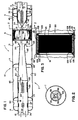
- Fig. 1 is a schematic cross-sectional view of a muffler assembly integral with a catalytic converter arrangement therein.
- Fig. 2 is a cross-sectional view taken generally along line 2-2, Fig. 1.
- Fig. 3 is an enlarged, fragmentary view of a portion of the arrangement shown in Fig. 1.
- Fig. 4 is a schematic cross-sectional view of a muffler assembly with a catalytic converter arrangement therein according to the present invention; in Fig. 4, the muffler assembly having an inlet and outlet generally adjacent a single end of the muffler shell, and a catalytic converter arrangement generally analogous to that shown in Figs. 1, 3, and 4.
- Fig. 5 is a schematic cross-sectional view taken generally along line 5-5, Fig. 4.
- FIG. 1 A first embodiment shown in Figs 1-3 does not form any part of the invention but is included herein as reference to provide a fuller understanding of the invention.
- the reference numeral 1, Fig. 1 generally designates a muffler assembly integral with a catalytic converter.
- the muffler assembly 1 has defined therein three general regions: an exhaust introduction, distribution and upstream acoustics region 5; a catalytic converter region 6; and a downstream acoustical or attenuation region 7.
- regions 5, 6 and 7 may be constructed separately, with the overall assembly prepared through utilization of appropriate clamps, segments, etc.
- the segments 5, 6 and 7 will be constructed in an overall unit 10 having an outer shell 11 with no segment seams or cross seams therein.
- cross seam in this context it is meant that the shell 11 is not segmented into longitudinally aligned segments, rather it comprises one longitudinal unit, typically (but not necessarily) having at least one and possibly more than one longitudinal seam.
- a unit 10 which is constructed with no cross seams, i.e., as a single longitudinal unit, will be referred to as an "integrated" unit. To a certain extent, it may be viewed as a muffler assembly having a catalytic converter positioned operably therein.
- a unit constructed in segments aligned coaxially and joined to one another along cross seams will be referred to as a “segmented” arrangement. It will be understood that to a great extent the principles of the present invention may be applied in either “integrated” or “segmented” units or arrangements. It is an advantage of the preferred embodiment of the present invention, however, that they are well adapted for arrangement as "integrated" units.
- the muffler assembly 1 is constructed to operate effectively and efficiently both as an exhaust noise muffler and as a catalytic converter.
- an exhaust noise muffler many of the principles of operation are found in, and can be derived from, certain known muffler constructions. With respect to these principles, attention is directed to U.S. Patents 3,672,464; 4,368,799; 4,580,657; 4,632,216; and 4,969,537.
- muffler assembly 1 comprises a cylindrical casing or shell 11 of a selected predetermined length.
- Annular end caps 13 and 14 respectively define an inlet aperture 17 and an outlet aperture 18.
- the shell 11 is generally cylindrical and defines a central longitudinal axis 20.
- An inlet tube 22 is positioned within inlet aperture 17.
- the inlet tube 22 has a generally cylindrical configuration and is aligned with its central longitudinal axis generally coextensive or coaxial with axis 20. It is noted that end portion 24 of inlet tube 22 is configured in a manner non-cylindrical and described in detail hereinbelow, for advantage.
- Outlet tube 26 is positioned within outlet aperture 18.
- Outlet tube 26 includes a generally cylindrical portion 27 aligned with a central longitudinal axis thereof extending generally coextensive with or coaxially with longitudinal axis 20.
- the exhaust gases are directed: (1) into assembly 1 by passage through inlet tube 22 as indicated by arrows 30; (2) into the internal region or volume 31 defined by casing or shell 11; and, (3) outwardly from assembly 1 by passage outwardly through outlet tube 26 as indicated by arrows 33.
- assembly 1 both sound attenuation (muffling) and emission improvement (catalytic conversion) occur.
- baffle 35 is constructed so as not to be permeable to the passage of the exhaust gases therethrough or thereacross.
- baffle 35 in cooperation with end cap 13 and shell 11 define a closed volume 37.
- inlet tube 22 is perforated along its length of extension within assembly 1, i.e., that portion of the tube 22 positioned internally of end cap 13 (that is positioned between end cap 13 and end cap 14) is perforated, as indicated by perforations 38.
- Certain of the perforations allow gas expansion (and sound travel) into volume 37, which assists in attenuation of sound to some degree.
- Regions such as volume 37 may be generally referred to as “resonating chambers" or “acoustics”, and similar structure positioned upstream of region 6 and also constructed and arranged for sound attenuation, will be referred to herein as "upstream acoustics.”
- the flow distribution element 44 generates distribution of exhaust gas flow within volume 45, i.e., the enclosed volume of shell 11 positioned immediately inwardly of baffle 35, for advantage.
- Portion 42 of inlet tube 22 includes previously defined end portion 24.
- Catalytic converter 50 Positioned immediately downstream of inlet tube 22 is catalytic converter 50.
- Catalytic converter 50 includes a substrate 51 having catalyst appropriately positioned thereon.
- the substrate 51 is gas permeable, i.e., the exhaust gases pass therethrough along the direction of arrow 53.
- the catalytic converter 50 includes sufficient catalyst therein to effect the desired conversion in the exhaust gases as they pass therethrough. Herein this will be referred to as "an effective amount" of catalyst.
- the substrate 51 is sized appropriately for this. Greater detail concerning the preferred catalytic converter 50 is provided hereinbelow.
- the flow distribution element 44 is sized and configured appropriately to substantially evenly distribute exhaust flow against the entire front or upstream surface 55 of the catalytic converter 50. In this manner, lifetime of use in the catalytic converter 50 is enhanced. Also, the more effective and even the distribution, the less likelihood of overload in any given portion of the catalytic converter 50. This will facilitate utilization of a catalytic converter minimal or relatively minimal thickness, which is advantageous.
- substantially evenly in this context it is meant that flow is distributed sufficiently to avoid substantial "dead” or "unused” volume in converter 50. Generally, as even a distribution as can be readily obtained, within acceptable backpressure limits is preferred.
- the catalytic converter 50 provides for little or no sound attenuation within the muffler.
- the space utilized by the catalytic converter is space or volume of little or no beneficial effect with respect to muffler operation. Under such conditions, minimal thickness or flow path catalytic converter will be preferred, so as not to substantially inhibit muffler (attenuation) operation.
- flow distribution element 44 comprises end 24 of tube 22 crimped or folded into a "star" or “four finned” configuration.
- Such an arrangement has been used in certain types of muffler assemblies before, see for example Wagner et al. US-A-4 969 537 referred to above.
- the crimping creates closed edges 56 and facilitates flow distribution.
- this advantageous distribution is applied in order to achieve relatively even cross-sectional distribution of airflow into and through a catalytic converter 50, to advantage.
- alternative flow distribution arrangements may be utilized in some applications.
- the portion 60 of the muffler assembly 1 in extension between the downstream surface 61 of the catalytic converter 50 and the outlet end cap 14 is referred to herein as the downstream acoustical or attenuation segment or end 7 of the assembly 1. It is not the case that all sound attenuation which occurs within the assembly 1 occurs within this region. However, the majority of the sound attenuation will occur in this portion of the assembly 1.
- the downstream acoustical segment 7 comprises structure placed to facilitate sound attenuation or sound control.
- resonating chambers or the like will be included therein.
- One such construction is illustrated in Fig. 1.
- the particular version illustrated in Fig. 1 utilizes a sonic choke arrangement 65 therein in association with resonating chambers, to achieve sound attenuation. It will be understood that a variety of alternate arrangements may be utilized.
- acoustical or attenuation segment 7 includes therein a converging or sonic choke arrangement 65 supported by sealed baffle 66.
- the volume 68 upstream from sealed baffle 66 will be constructed or tuned for advantageous low frequency sound attenuation. Such tuning will in general concern the precise location of the sealed baffle 66, i.e., adjustment in the size of volume 68. Constructions in which a sonic choke assembly similar to that illustrated as 65 are positioned within a muffler assembly 1 by a sealed baffle 66 advantageously, are described in U.S. Patents 3,672,464 and 4,969,537.
- sonic choke assembly 65 comprises a tube member 75 mounted coaxially with outlet tube 26 and, together with outlet tube 26, supported by baffles 66 and 77, and outlet end cap 18.
- tube member 75 may comprise an extension of an overall tube, having no cross seam, which includes both the tube member 75 and the outlet tube 26 as portions thereof.
- the outlet tube 26 comprises an end portion of tube member 75.
- the outlet tube 26 may comprise a separate extension of material from tube member 75; the outlet tube and tube member being joined along a cross seam such that they are oriented substantially coaxial with one another.
- the tube member 75 defines a central longitudinal axis positioned generally coextensive and coaxial with axis 20. In some constructions, a tube member 75 with a longitudinal axis off-set from alignment with the inlet axis may be used.
- tube member 75 in combination with outlet tube 26 defines exit flow for exhaust gases passing along the direction of arrow 53 through catalytic converter 50. More specifically, such gases pass through an interior 80 of the tube member 75 and outwardly through outlet tube 26, as indicated at arrows 33.
- volume 85 is defined within shell 11.
- An extension 88, of the combination of tube member 75 and outlet tube 26 extending through volume 85, is perforated as shown by perforations 84, to allow for expansion of gases into volume 85.
- Volume 85 will operate as a resonator or resonating chamber for attenuation of sound, in particular continued attenuation of low frequency and much of the medium frequency attenuation.
- the size of the volume 85 may be selected so that it is tuned for preferred sound attenuation including some high frequency attenuation as well.
- chamber 90 is defined, externally of tube member 75 and outlet tube 26, and internally of shell 11.
- the portion 91 of outlet tube 26 extending between baffle 77 and end cap 14 is perforated, to allow expansion of gases (and leakage of sound waves) into volume 90.
- the size and configuration of volume 90 may be tuned for selected medium and high frequency sound attenuation.
- tube member 75 includes a conical end 92 which converges from point 93 to neck 94, i.e., it converges in extension toward the catalytic converter.
- the tube member 75 diverges at flange 95 to lip 96; lip 96 defining a re-entry port for gasses passing through assembly 1.
- a sonic choke Such a construction is advantageous for preferred muffler operation and sound attenuation.
- Sonic chokes are described generally in Rowley et al. U.S. Patent 3,672,494.
- a variety of constructions may be utilized for the catalytic converter 50.
- One such construction is illustrated in Figs. 1 and 3.
- the catalytic converter 50 comprises a ceramic structure having a honeycomb-like configuration defining a plurality of longitudinal flow channels extending therethrough.
- the ceramic construction (or core) is indicated generally at 100.
- the ceramic core 100 is provided in a circular configuration, i.e., core 100 defines a cylindrically shaped item.
- core 100 defines a cylindrically shaped item.
- a ceramic cylinder having a large plurality of longitudinal channels extending therethrough is a somewhat brittle configuration. It is therefore preferably mounted such that it will be dampened from the shocks and vibrations generally associated with a muffler assembly in a diesel powered vehicle.
- the ceramic core 100 is provided with a dampening mantle or wrap 101 in extension around an outer periphery 102 thereof.
- the mantle 101 should be provided from a flexible, heat resistant material, such as a vermiculite pad.
- the material Interam® Mat III available from 3M, St. Paul, Minnesota 55144 is usable. In general, for the arrangement shown the mantle 101 would be about 0.12 in. (0.3 cm) to 0.25 in. (0.64 cm) thick.
- the mantle 101 is retained against the core 100 by retaining means such as a cylindrical casing 105 of sheet metal.
- the casing 105 is provided not only in extension around the outside of the mantle 101, but also with a pair of side flanges bent toward the front face 55 and rear face 61, respectively, of the core 100 to contain the mantle 101. That is, casing 105 has first and second side lips or rims 106 and 107 folded toward opposite sides of the core 100.
- a circular loop of rope or O-shaped gasket 109 is provided underneath each of the rims 106 and 107, to facilitate secure containment of the core 100 and mantle 101 within the casing 105, without damage.
- the preferred catalytic converter 50 illustrated is a self-contained or "canned" unit, positioned within shell 11.
- the converter comprises a ceramic core 100 positioned within a casing 105, and protected therein by the mantle 101 and rope rings 109.
- the converter 50 can thus be readily welded or otherwise secured and placed within shell 11, with good protection of the core 100 from extreme vibrations within the assembly 1.
- the mantle 101 and rings 109 will help protect the converter 50 from premature deterioration due to flow erosion.
- the ceramic core 100 will comprise an alumina magnesia silica (crystalline) ceramic, such as cordierite, which has been extruded from a clay, and then dried and fired to a crystalline construction.
- crystalline ceramics are prepared as catalytic converter cores by application of a wash coat thereto and then by dipping the core into a solution of catalyst. In some, the wash coat and catalyst are applied simultaneously.
- Typical catalysts utilized would be noble or precious metal catalysts, including for example platinum, palladium and rhodium. Other materials such as vanadium have also been used in catalytic converters.
- the core 100 should be extruded with a cell density of longitudinal passageways of 31 cells/cm 2 to 193 cells/cm 2 and preferably at least about 62 per cm 2 (400 per square inch) of front surface area.
- catalyst activity is a function of temperature. That is, a catalytic converter generally operates best when it is hottest(withindesignlimits). Thus, since the inlet end of a muffler assembly is hotter than the outlet end, it is generally preferable to position the catalytic converter toward the inlet end of the arrangement to the extent possible. Thus, for the arrangement shown in Fig. 1 the catalytic converter is generally positioned adjacent the flow distribution element.
- the catalytic converter will be generally preferably positioned within a distance of about 2-4 inches (5-10 cm), preferably about 2.0-3.0 inches (5-7.5 cm) and most preferably around 2.0 inches (5.0 cm) from the flow distribution element.
- the results of some simulated modeling and calculations with respect to this are presented hereinbelow.
- the catalytic converter takes up space in the muffler assembly otherwise utilizable for low-frequency sound attenuation. Since the catalytic converter does not facilitate sound attenuation and since sound attenuation will not generally take place in the space occupied by the catalytic converter, a problem with the catalytic converter positioning is that it interferes with sound attenuation. It is desirable, therefore, to render the catalytic converter as short as reasonably possible. This is facilitated by assuring good flow distribution across the front surface of the catalytic converter, as indicated above, and also by positioning the catalytic converter where it will operate at the hottest and thus most efficient.
- a catalytic converter utilizable in assemblies according to the present invention (as converters in muffler assemblies for diesel trucks) will need to be about 3.0-8.0 inches (7.6-20.3 cm) long and generally preferably about 5.0-6.0 inches (12.7-15.2 cm) long. It is foreseen that, therefore, in preferred constructions according to the present invention (for diesel engine mufflers) the muffler assembly will be about 5.0-6.0 inches (12.7-15.2 cm) longer than would a muffler assembly not having a catalytic converter positioned therein but utilized to achieve the same level of sound attenuation in a diesel engine exhaust stream.
- the population density of pores through the core be as high as reasonably obtainable.
- high porosity (with a large population of very small pores) is generally preferred.
- the catalytic converter be integrated with the muffler assembly, i.e., positioned therein, rather than positioned simply in a flow stream in series with a muffler assembly.
- the reasons for this include that it is foreseen that less overall backpressure will be generated by such a system.
- FIG. 4 and 5 An embodiment of an arrangement according to the present invention is depicted in Figs. 4 and 5.
- the embodiment of Figs. 4 and 5 concerns a muffler assembly wherein exhaust gas inlets and outlets for the muffler assembly are positioned on, or adjacent, a single end of the muffler shell.
- Muffler assembly 500 comprises a shell 502 having an exhaust gas flow inlet 503 and an exhaust gas flow outlet, 504.
- exhaust flow from an engine is directed into assembly 500 along a general direction of arrow 506.
- sound attenuation and catalytic conversion are conducted.
- Exhaust gas then exits assembly 500 along the path indicated by arrow 507.
- Exhaust gas flow through assembly 500, between inlet 503 and outlet 504 is generally indicated by arrows 509.
- the path of flow is dictated by flow directing means, as described.
- the exhaust gases are directed through catalytic converter assembly 512.
- the particular arrangement 512 depicted comprises core 513 surrounded by mantle 514 and casing 515.
- Core 513 has an upstream face 517 and a downstream face 518.
- normal exhaust gas flow during operation of assembly 500 is through core 513 from the upstream face 517 toward the downstream face 518.
- the arrangement according to Figs. 4 and 5 is generally distinguished from arrangement according to Fig. 1, by the relative locations of the inlet 503 and outlet 504 with respect to the catalytic converter assembly 512.
- the inlet 503 and outlet 504 are positioned in shell 502 at locations on the same side of core 513 as the upstream face 517.
- the inlet 22 and outlet 26 were positioned in shell 11 on opposite sides of catalytic converter 50.
- flow through the outlet of the embodiment of Fig. 4 is generally orthogonal to flow through the inlet; whereas for Fig. 1, flow through the outlet is generally parallel, and preferably coaxial, to flow through the inlet.
- a purpose for depiction of the embodiment shown in Figs. 4 and 5 is to illustrate how a muffler assembly 500 having the inlet 503 and outlet 504 positioned adjacent to the same end of the shell 502 can be adapted for utilization with a catalytic converter assembly 512 according to the present invention.
- inlet 503 comprises inlet tube 520 positioned within end 521 of shell 502, by end cap 523 and baffle 524. Both end cap 523 and baffle 524 are solid, except for central apertures 526 and 527, respectively, therein to allow extension of inlet tube 520 therebetween. Inlet tube 520 is solid, not perforated, in region 529 extending between end cap 523 and baffle 524. A reason for this is to prevent escape of inlet gases into volume 530, between end cap 523 and 524. Such an escape would allow exhaust gas flow to bypass catalytic converter assembly 512 as it is directed to outlet 504.
- inlet tube 520 is provided with an inlet diffuser construction 532.
- inlet diffuser construction 532 comprises an extension 533 of tube 520 having perforations 534 therein and a domed, solid, nonperforated end cap 535 positioned in an outlet end 536 of extension 533.
- perforations in extension 533 the exhaust gases will flow outwardly from inlet diffuser 532 and expand into volume 540, as they pass through assembly 500.
- the perforations 534 also allow for escape of sound from tube 520.
- Volume 540 is in general defined by baffle 524, upstream face 517 of catalytic converter assembly 512, and internal shell 542.
- internal shell 542 comprises a cylindrical extension 543 having a smaller cross-sectional area than shell 502. Extension 543 is positioned within shell 502 with annular space 544 extending therearound.
- Spacers 546 position shell 542 within assembly 500 spaced from shell 502. Spacers 546 may comprise a variety of arrangements. For the particular embodiment shown in Figs. 4 and 5, spacers 546 comprise U-channels 547.
- Catalytic converter assembly 512 is supported within internal shell 542 in a manner analogous to the way the catalytic converter assembly 50 was supported within shell 11, Figs. 1 and 3.
- Volume 540 comprises an expansion volume which will operate in part as an acoustic attenuator (upstream acoustics), to muffle sound.
- the geometry and dimensions of volume 540 may be selected to achieve a preferred amount of sound attenuation, utilizing known muffler tuning techniques.
- the nature of attenuation occurring in volume 540 will be similar to that occurring in volume 68, Fig. 1, i.e. low frequency and middle frequency attenuation to the greatest degree, with some high frequency attenuation.
- volume 549 represents an expansion chamber for the exhaust gases. Within volume 549, further attenuation occurs.
- the size and shape of volume 549 can be tuned to achieve a preferred amount of acoustical attenuation.
- Assembly 500 is provided with internal baffle 551 and end cap 552. Both are preferably solid, not perforated.
- Internal baffle 551 is provided with central aperture 555 having tube 556 extending therethrough.
- Tube 556 has a re-entry port 557 on an end thereof adjacent converter 512.
- Port 558 is provided on an opposite end of tube 556.
- Baffle 551 and end cap 552 define volume 559, within assembly 500.
- baffle 551, end cap 552, tube 556 and volume 559 comprise an acoustical attenuator or resonating chamber 560.
- the tube 556 then, extends between resonating chambers 549 and 560.
- the size and geometry of the chamber 560, as well as the shape of baffle 551 end cap 552 and the size, shape and length of tube 556, may be tuned or selected for preferred amount of sound attenuation within assembly 500. It is anticipated that in general, medium and high frequency attenuation will be conducted, within volume 559.
- the annular space 544 comprises an exhaust flow annulus which includes flow spaces 563, within U-channels 547 and flow spaces 564 between the U-channels 547. It will be understood that alternate spacers 546 (to U-channels 547) could be selected, which would not be hollow to allow gas flow to go through.
- Arrangement 500 may be constructed of a variety of materials.
- sheet metal may be utilized for internal components, tubes, baffles and the like, as for conventional muffler constructions.
- Catalytic converter assembly 512 again, may be according to any of the variations described hereinabove with respect to other embodiments.
- Figs. 4 and 5 will be highly advantageous for certain applications.
- a muffler assembly with the inlet and outlet positioned adjacent a single end thereof.
- a limited amount of space or volume may be available, for positioning of the muffler assembly.
- a catalytic converter is to be positioned within that muffler assembly, it must be designed such that appropriate exhaust gas flow will occur, without undue back pressure.
- a catalytic converter core In general, the operation of a catalytic converter core is a function of its volume. Efficiency of conversion can be improved by either increasing depth, increasing cross-sectional area, or both. A problem with increasing depth is that a greater amount of friction to exhaust gas flow therethrough is provided, thus the cbre becomes a greater and greater restriction to exhaust gas flow (resulting in increasing back pressure).
- the arrangement shown in Figs. 4 and 5 allows for a substantial cross-sectional area of the catalytic converter core 513 within a given volume for a muffler assembly shell 502.
Landscapes
- Chemical & Material Sciences (AREA)
- Engineering & Computer Science (AREA)
- Chemical Kinetics & Catalysis (AREA)
- Combustion & Propulsion (AREA)
- Mechanical Engineering (AREA)
- General Engineering & Computer Science (AREA)
- Health & Medical Sciences (AREA)
- Toxicology (AREA)
- Exhaust Gas After Treatment (AREA)
- Exhaust Silencers (AREA)
Abstract
Claims (8)
- Dispositif comprenant :(a) un agencement formant silencieux (500) comprenant : une enveloppe extérieure (502) comportant une première extrémité, une seconde extrémité, une entrée d'échappement (503) dans ladite première extrémité de ladite enveloppe extérieure, et une sortie d'échappement (504) ;
(i) ledit agencement formant silencieux comprenant un agencement d'atténuation de bruit à l'intérieur de ladite enveloppe ;(b) un agencement formant convertisseur catalytique (512) placé à l'intérieur dudit agencement formant silencieux ; ledit agencement formant convertisseur catalytique comprenant une partie centrale de convertisseur (513) comportant une surface amont (517) et une surface aval opposée (518) ; ladite partie centrale de convertisseur ayant une périphérie extérieure ;(c) une enveloppe intérieure placée à l'intérieur et espacée de ladite enveloppe extérieure, définissant ainsi entre elles un espace annulaire (544) d'écoulement des gaz d'échappement ;
(i) ladite partie centrale de convertisseur étant placée de manière fonctionnelle à l'intérieur de ladite enveloppe intérieure ;(d) ledit agencement d'atténuation de bruit comprenant un tube atténuateur de bruit (556) comportant un orifice d'entrée (557) espacé de ladite surface aval de la partie centrale de convertisseur ;(e) un agencement d'écoulement d'échappement destiné à diriger les gaz d'échappement au travers dudit agencement formant convertisseur catalytique, selon une direction d'écoulement allant de ladite surface amont vers ladite surface aval, chaque fois que des gaz d'échappement s'écoulent de manière opérable au travers dudit agencement formant silencieux, de ladite entrée d'échappement vers ladite sortie d'échappement ;(f) un agencement d'écoulement annulaire (544) destiné à diriger les gaz d'échappement, une fois que les gaz d'échappement ont été dirigés au travers de la partie centrale de convertisseur catalytique, dans une direction passant devant la partie centrale de convertisseur et autour de la périphérie extérieure de celle-ci, dans une direction d'écoulement allant de la surface aval de la partie centrale de convertisseur vers la surface amont de la partie centrale de convertisseur ;(i) ledit agencement d'écoulement annulaire dirigeant le flux de gaz d'échappement au travers dudit espace annulaire d'écoulement d'échappement et vers ladite sortie ;(ii) ledit agencement d'écoulement annulaire dirigeant le flux de gaz d'échappement dans ledit espace annulaire d'écoulement d'échappement en un endroit situé entre ledit orifice d'entrée du tube atténuateur de bruit et ladite surface amont de la partie centrale de convertisseur de telle sorte qu'en service, les gaz peuvent, sans y être forcés, s'écouler depuis ladite surface aval de la partie centrale de convertisseur dans ledit espace annulaire d'écoulement d'échappement sans être dirigés au travers dudit tube atténuateur de bruit ; et(g) ladite enveloppe extérieure (502) étant construite et disposée avec ladite entrée des gaz d'échappement placée dans ladite enveloppe extérieure (502) en un endroit plus proche de ladite surface amont de la partie centrale de convertisseur catalytique que ladite surface aval de la partie centrale de convertisseur catalytique ; et ladite enveloppe extérieure (502) étant construite et disposée avec ladite sortie des gaz d'échappement placée dans ladite enveloppe extérieure (502) en un endroit plus proche de ladite surface amont de la partie centrale de convertisseur catalytique que ladite surface aval de la partie centrale de convertisseur catalytique ; ladite partie centrale de convertisseur catalytique étant physiquement placée entre ladite seconde extrémité de l'enveloppe extérieure (502) et les deux dites entrée d'échappement et sortie d'échappement. - Dispositif selon la revendication 1, dans lequel ledit agencement d'atténuation de bruit comprend des éléments acoustiques aval comprenant ledit tube atténuateur de bruit s'étendant d'une chambre de résonance (548) à une seconde chambre de résonance (560).
- Dispositif selon la revendication 1, dans lequel ledit agencement formant convertisseur catalytique comprend une partie centrale en feuille métallique mince (120) comportant une quantité efficace de catalyseur dispersée sur celle-ci.
- Dispositif selon la revendication 1, dans lequel ledit convertisseur catalytique comprend une partie centrale en céramique (100) comportant une quantité efficace de catalyseur dispersée sur celle-ci.
- Dispositif selon la revendication 1, dans lequel ledit convertisseur catalytique comprend un manchon isolant (101) enroulé autour de ladite partie centrale en céramique.
- Dispositif selon la revendication 1, dans lequel ledit convertisseur catalytique comprend:(a) un manchon isolant souple (101) disposé autour de ladite partie centrale en céramique ; et(b) un gainage en tôle (105) enroulé autour dudit manchon isolant souple.
- Dispositif selon la revendication 1, dans lequel :
(a) ledit élément formant partie centrale poreux est placé à une distance comprise entre 2 et 4 pouces (51 mm à 102 mm) environ dudit agencement de répartition de l'écoulement. - Dispositif selon la revendication 1, dans lequel un élément formant partie centrale poreux est placé à une distance comprise entre 2,0 et 3,0 pouces (51 mm à 76 mm) environ dudit agencement de répartition de l'écoulement.
Applications Claiming Priority (5)
| Application Number | Priority Date | Filing Date | Title |
|---|---|---|---|
| US07/889,949 US5355973A (en) | 1992-06-02 | 1992-06-02 | Muffler with catalytic converter arrangement; and method |
| US889949 | 1992-06-02 | ||
| US08/025,058 US5426269A (en) | 1992-06-02 | 1993-03-02 | Muffler with catalytic converter arrangement; and method |
| US25058 | 1993-03-02 | ||
| PCT/US1993/004913 WO1993024744A2 (fr) | 1992-06-02 | 1993-05-20 | Silencieux avec dispositif convertisseur catalytique |
Publications (2)
| Publication Number | Publication Date |
|---|---|
| EP0643799A1 EP0643799A1 (fr) | 1995-03-22 |
| EP0643799B1 true EP0643799B1 (fr) | 1997-09-10 |
Family
ID=26699210
Family Applications (1)
| Application Number | Title | Priority Date | Filing Date |
|---|---|---|---|
| EP93914107A Expired - Lifetime EP0643799B1 (fr) | 1992-06-02 | 1993-05-20 | Silencieux avec dispositif convertisseur catalytique |
Country Status (8)
| Country | Link |
|---|---|
| US (1) | US5426269A (fr) |
| EP (1) | EP0643799B1 (fr) |
| JP (1) | JP3481621B2 (fr) |
| AU (1) | AU676171B2 (fr) |
| BR (1) | BR9306467A (fr) |
| CA (1) | CA2137163A1 (fr) |
| DE (1) | DE69313848T2 (fr) |
| WO (1) | WO1993024744A2 (fr) |
Cited By (1)
| Publication number | Priority date | Publication date | Assignee | Title |
|---|---|---|---|---|
| US7537083B2 (en) | 2000-03-21 | 2009-05-26 | Silentor Holdings A/S | Silencer containing one or more porous bodies |
Families Citing this family (64)
| Publication number | Priority date | Publication date | Assignee | Title |
|---|---|---|---|---|
| US5355973A (en) | 1992-06-02 | 1994-10-18 | Donaldson Company, Inc. | Muffler with catalytic converter arrangement; and method |
| FI98403C (fi) | 1994-07-01 | 1997-06-10 | Waertsilae Diesel Int | Menetelmä äänenvaimenninyksikön käyttämiseksi ja järjestelmä menetelmän soveltamiseksi isossa dieselmoottorissa |
| US6220021B1 (en) * | 1995-05-19 | 2001-04-24 | Silentor Notox A/S | Silencer with incorporated catalyst |
| DE19611133A1 (de) * | 1996-03-21 | 1997-09-25 | Eberspaecher J | Schalldämpfer-Anordnung |
| DK57996A (da) | 1996-05-15 | 1997-11-16 | Silentor As | Lyddæmper |
| JP3816581B2 (ja) * | 1996-06-21 | 2006-08-30 | 株式会社共立 | 内燃エンジンのマフラー |
| DE19626980A1 (de) * | 1996-07-04 | 1998-02-26 | Roth Technik Austria | Schalldämpfer für Kraftfahrzeuge |
| ES2376496T3 (es) | 1996-09-30 | 2012-03-14 | Silentor Holding A/S | Silenciador de flujo de gas. |
| US6520286B1 (en) | 1996-09-30 | 2003-02-18 | Silentor Holding A/S | Silencer and a method of operating a vehicle |
| DE19802624A1 (de) * | 1998-01-24 | 1999-07-29 | Eberspaecher J Gmbh & Co | Abgasschalldämpfer für Verbrennungsmotoren |
| US6082487A (en) * | 1998-02-13 | 2000-07-04 | Donaldson Company, Inc. | Mufflers for use with engine retarders; and methods |
| AU2599599A (en) * | 1998-02-13 | 1999-08-30 | Donaldson Company Inc. | Mufflers for use with engine retarders; and methods |
| US7281606B2 (en) | 1998-08-18 | 2007-10-16 | Marocco Gregory M | Exhaust sound and emission control systems |
| US6935461B2 (en) * | 1998-08-18 | 2005-08-30 | Gregory M. Marocco | Exhaust sound and emission control systems |
| US6651773B1 (en) | 2002-09-24 | 2003-11-25 | Gregory M. Marocco | Exhaust sound attenuation and control system |
| US7549511B2 (en) * | 1998-08-18 | 2009-06-23 | Marocco Gregory M | Exhaust sound and emission control systems |
| US6148519A (en) * | 1998-09-18 | 2000-11-21 | Donaldson Company, Inc. | Apparatus for installing a packing material in a muffler assembly; and methods thereof |
| KR100405051B1 (ko) * | 2001-04-18 | 2003-11-07 | 한국과학기술연구원 | 내연기관의 배기 소음 제어장치 |
| DE10143157A1 (de) * | 2001-09-04 | 2003-03-27 | Ballard Power Systems | Vorrichtung zur gleichmäßigen Verteilung eines Medienstroms |
| US20030089105A1 (en) * | 2001-10-17 | 2003-05-15 | Reeves Gary D. | Exhaust treatment apparatus and method of making |
| US6715583B2 (en) * | 2002-07-01 | 2004-04-06 | Santos Miguel Radhames | Silencer and power enhancement environmental device |
| US7278259B2 (en) * | 2002-08-23 | 2007-10-09 | Donaldson Company, Inc. | Apparatus for emissions control, system, and methods |
| US7257942B2 (en) * | 2002-08-23 | 2007-08-21 | Donaldson Company, Inc. | Apparatus for emissions control, systems, and methods |
| DE10316799A1 (de) * | 2003-04-11 | 2004-10-28 | Man Nutzfahrzeuge Ag | Kombinierte Abgasnachbehandlungs-/Schalldämpfungsvorrichtung im Abgasstrang einer Brennkraftmaschine |
| US7174992B2 (en) * | 2004-04-05 | 2007-02-13 | Fleetguard, Inc. | Muffler with secondary flow path |
| EP1797295A1 (fr) * | 2004-09-08 | 2007-06-20 | Donaldson Company, Inc. | Joint pour une composante de systeme d'echappement des moteurs |
| EP1799980A1 (fr) * | 2004-09-08 | 2007-06-27 | Donaldson Company, Inc. | Construction d'un composant d'un systeme d'echappement d'un moteur |
| US7451594B2 (en) * | 2004-10-01 | 2008-11-18 | Donaldson Company, Inc. | Exhaust flow distribution device |
| US20060277900A1 (en) * | 2005-03-17 | 2006-12-14 | Hovda Allan T | Service joint for an engine exhaust system component |
| US7413716B2 (en) * | 2005-04-08 | 2008-08-19 | Homelite Technologies, Ltd. | Muffler with catalytic converter |
| US7380397B2 (en) * | 2005-09-08 | 2008-06-03 | Chih-Kuang Chang | Automobile exhaust pipe assembly |
| DE102005044442B4 (de) * | 2005-09-09 | 2009-04-30 | As-Motor Germany Gmbh & Co. Kg | Abgasschalldämpfer |
| US20070131481A1 (en) * | 2005-12-12 | 2007-06-14 | John Mordarski | Method and apparatus for attenuating sound in a vehicle exhaust system |
| US8110151B2 (en) * | 2006-04-03 | 2012-02-07 | Donaldson Company, Inc. | Exhaust flow distribution device |
| US8091344B2 (en) * | 2006-06-13 | 2012-01-10 | Cummins Inc. | System for modifying exhaust gas flow through an aftertreatment device |
| US20080017444A1 (en) * | 2006-07-19 | 2008-01-24 | Dowdy Bobby J | Vehicle muffler |
| US7748212B2 (en) * | 2007-03-09 | 2010-07-06 | Cummins Filtration Ip, Inc. | Exhaust aftertreatment system with flow distribution |
| US8740590B2 (en) * | 2007-12-17 | 2014-06-03 | Southern Gas Association Gas Machinery Research Council | Hyperbolic horn for pulsation filter device used with gas compressor |
| DE102008022081A1 (de) * | 2008-05-05 | 2009-11-12 | J. Eberspächer GmbH & Co. KG | Abgasbehandlungseinrichtung |
| FR2932215B1 (fr) | 2008-06-09 | 2016-05-27 | Technip France | Installation d'exploitation de fluide dans une etendue d'eau, et procede associe |
| US9009967B2 (en) * | 2008-07-31 | 2015-04-21 | Caterpillar Inc. | Composite catalyst substrate |
| KR100969053B1 (ko) * | 2008-09-09 | 2010-07-09 | 현대자동차주식회사 | 촉매 내장형 머플러 |
| JP5390281B2 (ja) * | 2009-07-02 | 2014-01-15 | ヤンマー株式会社 | 排気ガス浄化装置 |
| JP5912221B2 (ja) * | 2010-02-01 | 2016-04-27 | フタバ産業株式会社 | 内燃機関用マフラ |
| JP2013519037A (ja) * | 2010-02-02 | 2013-05-23 | イー・アイ・デュポン・ドウ・ヌムール・アンド・カンパニー | 一体化された触媒コンバータおよびポリマー製マフラー本体を有するマフラー |
| DE102010015271A1 (de) | 2010-04-15 | 2011-10-20 | J. Eberspächer GmbH & Co. KG | Abgasbehandlungseinrichtung |
| US8393147B2 (en) | 2010-06-30 | 2013-03-12 | Caterpillar Inc. | Exhaust system having an aftertreatment module |
| DE102010034743A1 (de) | 2010-08-19 | 2012-02-23 | J. Eberspächer GmbH & Co. KG | Abgasreinigungsvorrichtung, Abgasanlage, Ausbauverfahren |
| US8756923B2 (en) * | 2010-11-24 | 2014-06-24 | Cnh Industrial America Llc | Mixing pipe for SCR mufflers |
| US20130174817A1 (en) * | 2012-01-05 | 2013-07-11 | Julie N. Brown | Exhaust system and method for an internal combustion engine |
| JP5912605B2 (ja) * | 2012-02-03 | 2016-04-27 | 本田技研工業株式会社 | 排気マフラー装置 |
| US9238199B1 (en) * | 2013-03-15 | 2016-01-19 | Honeywell International, Inc. | Combined flow mixing, tempering and noise suppressing apparatus for a selective catalytic reduction system and method of use thereof |
| US9291081B2 (en) | 2013-05-07 | 2016-03-22 | Tenneco Automotive Operating Company Inc. | Axial flow atomization module |
| US9289724B2 (en) | 2013-05-07 | 2016-03-22 | Tenneco Automotive Operating Company Inc. | Flow reversing exhaust gas mixer |
| US9364790B2 (en) | 2013-05-07 | 2016-06-14 | Tenneco Automotive Operating Company Inc. | Exhaust mixing assembly |
| US9314750B2 (en) | 2013-05-07 | 2016-04-19 | Tenneco Automotive Operating Company Inc. | Axial flow atomization module |
| US9352276B2 (en) | 2013-05-07 | 2016-05-31 | Tenneco Automotive Operating Company Inc. | Exhaust mixing device |
| US9334781B2 (en) | 2013-05-07 | 2016-05-10 | Tenneco Automotive Operating Company Inc. | Vertical ultrasonic decomposition pipe |
| US9435240B2 (en) | 2013-08-06 | 2016-09-06 | Tenneco Automotive Operating Company Inc. | Perforated mixing pipe with swirler |
| US9410464B2 (en) | 2013-08-06 | 2016-08-09 | Tenneco Automotive Operating Company Inc. | Perforated mixing pipe with swirler |
| DE202014102872U1 (de) * | 2014-06-10 | 2014-07-09 | Tenneco Gmbh | Abgasmischer |
| DE102014016448A1 (de) * | 2014-11-06 | 2016-05-12 | Man Diesel & Turbo Se | Abgasnachbehandlungsvorrichtung und Verfahren zur Abgasnachbehandlung |
| DE102014222698B4 (de) * | 2014-11-06 | 2017-12-14 | Eberspächer Exhaust Technology GmbH & Co. KG | Abgasnachbehandlungseinrichtung mit Injektionsabschnitt |
| US9534525B2 (en) | 2015-05-27 | 2017-01-03 | Tenneco Automotive Operating Company Inc. | Mixer assembly for exhaust aftertreatment system |
Family Cites Families (27)
| Publication number | Priority date | Publication date | Assignee | Title |
|---|---|---|---|---|
| DE673707C (de) * | 1937-02-05 | 1939-03-27 | Rudolf Wieth | Schalldaempfer fuer Brennkraftmaschinen mit mehreren Kammern |
| US3180712A (en) * | 1962-12-26 | 1965-04-27 | Universal Oil Prod Co | Two-stage converter-muffler |
| US3672464A (en) * | 1970-09-16 | 1972-06-27 | Donaldson Co Inc | Muffler for internal combustion engine |
| GB1406076A (en) * | 1971-08-31 | 1975-09-10 | Alfa Romeo Spa | Vertical-flow catalytic muffler |
| CA976771A (en) * | 1972-08-21 | 1975-10-28 | Tenneco Inc. | Catalyst device for exhaust system of internal combustion engine |
| DE2314465C3 (de) * | 1973-03-23 | 1978-12-07 | Volkswagenwerk Ag, 3180 Wolfsburg | Einrichtung zur katalytischen Abgasreinigung |
| US3972687A (en) * | 1974-03-21 | 1976-08-03 | Paul Gillet Gmbh | Catalytic converter having pressurized-gas support means |
| US4050903A (en) * | 1976-10-29 | 1977-09-27 | Uop Inc. | Combination muffler and catalytic converter |
| US4209493A (en) * | 1977-07-11 | 1980-06-24 | Nelson Industries, Inc. | Combination catalytic converter and muffler for an exhaust system |
| US4393652A (en) * | 1980-07-23 | 1983-07-19 | Munro John H | Exhaust system for internal combustion engines |
| US4541240A (en) * | 1980-07-23 | 1985-09-17 | Munro John H | Exhaust system for internal combustion engines |
| US4368799A (en) * | 1980-10-16 | 1983-01-18 | Donaldson Company, Inc. | Straight-through flow muffler |
| JPS6131131Y2 (fr) * | 1981-03-26 | 1986-09-10 | ||
| US4580657A (en) * | 1983-06-16 | 1986-04-08 | Donaldson Company, Inc. | Integral fluted tube for sound suppression and exhaust ejection |
| WO1985004217A1 (fr) * | 1984-03-15 | 1985-09-26 | Jenbacher Werke Aktiengesellschaft | Epurateur catalytique des gaz d'échappement de moteurs a combustion interne fonctionnant comme silencieux |
| US4632216A (en) * | 1984-06-27 | 1986-12-30 | Donaldson Company, Inc. | Muffler apparatus and method for making same |
| US4601168A (en) * | 1984-12-12 | 1986-07-22 | Harris Harold L | Noise and emission control apparatus |
| DE3538107A1 (de) * | 1985-10-26 | 1987-04-30 | Man Technologie Gmbh | Filter zur reinigung von abgasen |
| DE3538109C1 (de) * | 1985-10-26 | 1987-02-26 | Man Technologie Gmbh | Dieselmotor mit Russfilter |
| US4851015A (en) * | 1987-08-21 | 1989-07-25 | Donaldson Company, Inc. | Muffler apparatus with filter trap and method of use |
| DE3729477C3 (de) * | 1987-09-03 | 1999-09-09 | Stihl Maschf Andreas | Abgasschalldämpfer für Zweitaktmotoren, insbesondere für tragbare Arbeitsgeräte wie Motorkettensägen |
| JPH01125512A (ja) * | 1987-11-09 | 1989-05-18 | Shin Caterpillar Mitsubishi Ltd | ディーゼルエンジンの排出微粒子処理装置 |
| CA1262869A (fr) * | 1988-06-23 | 1989-11-14 | Glen Knight | Echappement a combinaison de silencieux et convertisseur catalytique |
| US4969537A (en) * | 1988-11-10 | 1990-11-13 | Donaldson Company, Inc. | Muffler assembly and method of manufacture |
| SE465834B (sv) * | 1989-05-29 | 1991-11-04 | Electrolux Ab | Anordning foer avgasrening till foerbraenningsmotor t ex kedjesaagmotor |
| US5140813A (en) * | 1990-10-31 | 1992-08-25 | Whittenberger William A | Composite catalytic converter |
| US5139107A (en) * | 1990-12-11 | 1992-08-18 | Kioritz Corporation | Exhaust muffler for internal combustion engines |
-
1993
- 1993-03-02 US US08/025,058 patent/US5426269A/en not_active Expired - Fee Related
- 1993-05-20 BR BR9306467A patent/BR9306467A/pt not_active IP Right Cessation
- 1993-05-20 DE DE69313848T patent/DE69313848T2/de not_active Expired - Fee Related
- 1993-05-20 JP JP50069394A patent/JP3481621B2/ja not_active Expired - Fee Related
- 1993-05-20 CA CA002137163A patent/CA2137163A1/fr not_active Abandoned
- 1993-05-20 WO PCT/US1993/004913 patent/WO1993024744A2/fr active IP Right Grant
- 1993-05-20 AU AU43886/93A patent/AU676171B2/en not_active Ceased
- 1993-05-20 EP EP93914107A patent/EP0643799B1/fr not_active Expired - Lifetime
Cited By (1)
| Publication number | Priority date | Publication date | Assignee | Title |
|---|---|---|---|---|
| US7537083B2 (en) | 2000-03-21 | 2009-05-26 | Silentor Holdings A/S | Silencer containing one or more porous bodies |
Also Published As
| Publication number | Publication date |
|---|---|
| EP0643799A1 (fr) | 1995-03-22 |
| JP3481621B2 (ja) | 2003-12-22 |
| AU676171B2 (en) | 1997-03-06 |
| AU4388693A (en) | 1993-12-30 |
| WO1993024744A2 (fr) | 1993-12-09 |
| BR9306467A (pt) | 1998-06-30 |
| US5426269A (en) | 1995-06-20 |
| WO1993024744A3 (fr) | 1994-03-17 |
| DE69313848T2 (de) | 1998-04-23 |
| JPH07507374A (ja) | 1995-08-10 |
| DE69313848D1 (de) | 1997-10-16 |
| CA2137163A1 (fr) | 1993-12-09 |
Similar Documents
| Publication | Publication Date | Title |
|---|---|---|
| EP0643799B1 (fr) | Silencieux avec dispositif convertisseur catalytique | |
| US5355973A (en) | Muffler with catalytic converter arrangement; and method | |
| US7281606B2 (en) | Exhaust sound and emission control systems | |
| US5808245A (en) | Vertical mount catalytic converter muffler | |
| US5220789A (en) | Integral unitary manifold-muffler-catalyst device | |
| US5365025A (en) | Low backpressure straight-through reactive and dissipative muffler | |
| US6935461B2 (en) | Exhaust sound and emission control systems | |
| US4209493A (en) | Combination catalytic converter and muffler for an exhaust system | |
| JP3231852B2 (ja) | 内燃機関の触媒コンバータに組み込まれたサイレンサ | |
| JP3314241B2 (ja) | 自動二輪車用エンジンの排気浄化装置 | |
| US6651773B1 (en) | Exhaust sound attenuation and control system | |
| KR20000011089A (ko) | 소음기 | |
| US7549511B2 (en) | Exhaust sound and emission control systems | |
| US7282185B2 (en) | Emission control apparatus | |
| US4779703A (en) | Silencing device for internal combustion engine | |
| JP4339070B2 (ja) | 排気浄化装置 | |
| US20200182111A1 (en) | Exhaust device | |
| KR101633898B1 (ko) | 매연과 소음을 동시에 저감하는 일체형 복합장치 | |
| JP3099733B2 (ja) | 小型エンジン用排気ガス浄化装置 | |
| JPS595138Y2 (ja) | 排気浄化器兼用消音器 | |
| KR200233543Y1 (ko) | 차량의 배기가스 저감용 머플러 | |
| JPS5943457Y2 (ja) | 消音器 | |
| JP2000045761A (ja) | 触媒コンバータ | |
| JPH0586844A (ja) | 自動二輪車の排ガス浄化装置 | |
| JPH0295714A (ja) | 内熱機関の排ガス処理装置 |
Legal Events
| Date | Code | Title | Description |
|---|---|---|---|
| PUAI | Public reference made under article 153(3) epc to a published international application that has entered the european phase |
Free format text: ORIGINAL CODE: 0009012 |
|
| 17P | Request for examination filed |
Effective date: 19941212 |
|
| AK | Designated contracting states |
Kind code of ref document: A1 Designated state(s): DE FR GB IT SE |
|
| 17Q | First examination report despatched |
Effective date: 19950411 |
|
| GRAG | Despatch of communication of intention to grant |
Free format text: ORIGINAL CODE: EPIDOS AGRA |
|
| GRAH | Despatch of communication of intention to grant a patent |
Free format text: ORIGINAL CODE: EPIDOS IGRA |
|
| GRAH | Despatch of communication of intention to grant a patent |
Free format text: ORIGINAL CODE: EPIDOS IGRA |
|
| GRAA | (expected) grant |
Free format text: ORIGINAL CODE: 0009210 |
|
| AK | Designated contracting states |
Kind code of ref document: B1 Designated state(s): DE FR GB IT SE |
|
| REF | Corresponds to: |
Ref document number: 69313848 Country of ref document: DE Date of ref document: 19971016 |
|
| ET | Fr: translation filed | ||
| ITF | It: translation for a ep patent filed | ||
| PLBE | No opposition filed within time limit |
Free format text: ORIGINAL CODE: 0009261 |
|
| STAA | Information on the status of an ep patent application or granted ep patent |
Free format text: STATUS: NO OPPOSITION FILED WITHIN TIME LIMIT |
|
| 26N | No opposition filed | ||
| REG | Reference to a national code |
Ref country code: GB Ref legal event code: IF02 |
|
| PGFP | Annual fee paid to national office [announced via postgrant information from national office to epo] |
Ref country code: GB Payment date: 20050406 Year of fee payment: 13 |
|
| PGFP | Annual fee paid to national office [announced via postgrant information from national office to epo] |
Ref country code: SE Payment date: 20050503 Year of fee payment: 13 |
|
| PGFP | Annual fee paid to national office [announced via postgrant information from national office to epo] |
Ref country code: FR Payment date: 20050517 Year of fee payment: 13 |
|
| PGFP | Annual fee paid to national office [announced via postgrant information from national office to epo] |
Ref country code: DE Payment date: 20050531 Year of fee payment: 13 |
|
| PG25 | Lapsed in a contracting state [announced via postgrant information from national office to epo] |
Ref country code: GB Free format text: LAPSE BECAUSE OF NON-PAYMENT OF DUE FEES Effective date: 20060520 |
|
| PG25 | Lapsed in a contracting state [announced via postgrant information from national office to epo] |
Ref country code: SE Free format text: LAPSE BECAUSE OF NON-PAYMENT OF DUE FEES Effective date: 20060521 |
|
| PGFP | Annual fee paid to national office [announced via postgrant information from national office to epo] |
Ref country code: IT Payment date: 20060531 Year of fee payment: 14 |
|
| PG25 | Lapsed in a contracting state [announced via postgrant information from national office to epo] |
Ref country code: DE Free format text: LAPSE BECAUSE OF NON-PAYMENT OF DUE FEES Effective date: 20061201 |
|
| EUG | Se: european patent has lapsed | ||
| GBPC | Gb: european patent ceased through non-payment of renewal fee |
Effective date: 20060520 |
|
| REG | Reference to a national code |
Ref country code: FR Ref legal event code: ST Effective date: 20070131 |
|
| PG25 | Lapsed in a contracting state [announced via postgrant information from national office to epo] |
Ref country code: FR Free format text: LAPSE BECAUSE OF NON-PAYMENT OF DUE FEES Effective date: 20060531 |
|
| PG25 | Lapsed in a contracting state [announced via postgrant information from national office to epo] |
Ref country code: IT Free format text: LAPSE BECAUSE OF NON-PAYMENT OF DUE FEES Effective date: 20070520 |