US4779703A - Silencing device for internal combustion engine - Google Patents
Silencing device for internal combustion engine Download PDFInfo
- Publication number
- US4779703A US4779703A US07/034,961 US3496187A US4779703A US 4779703 A US4779703 A US 4779703A US 3496187 A US3496187 A US 3496187A US 4779703 A US4779703 A US 4779703A
- Authority
- US
- United States
- Prior art keywords
- expansion chamber
- exhaust pipe
- exhaust
- conduit
- air gap
- Prior art date
- Legal status (The legal status is an assumption and is not a legal conclusion. Google has not performed a legal analysis and makes no representation as to the accuracy of the status listed.)
- Expired - Lifetime
Links
Images

Classifications
-
- F—MECHANICAL ENGINEERING; LIGHTING; HEATING; WEAPONS; BLASTING
- F01—MACHINES OR ENGINES IN GENERAL; ENGINE PLANTS IN GENERAL; STEAM ENGINES
- F01N—GAS-FLOW SILENCERS OR EXHAUST APPARATUS FOR MACHINES OR ENGINES IN GENERAL; GAS-FLOW SILENCERS OR EXHAUST APPARATUS FOR INTERNAL COMBUSTION ENGINES
- F01N1/00—Silencing apparatus characterised by method of silencing
- F01N1/02—Silencing apparatus characterised by method of silencing by using resonance
-
- F—MECHANICAL ENGINEERING; LIGHTING; HEATING; WEAPONS; BLASTING
- F01—MACHINES OR ENGINES IN GENERAL; ENGINE PLANTS IN GENERAL; STEAM ENGINES
- F01N—GAS-FLOW SILENCERS OR EXHAUST APPARATUS FOR MACHINES OR ENGINES IN GENERAL; GAS-FLOW SILENCERS OR EXHAUST APPARATUS FOR INTERNAL COMBUSTION ENGINES
- F01N1/00—Silencing apparatus characterised by method of silencing
- F01N1/08—Silencing apparatus characterised by method of silencing by reducing exhaust energy by throttling or whirling
-
- F—MECHANICAL ENGINEERING; LIGHTING; HEATING; WEAPONS; BLASTING
- F01—MACHINES OR ENGINES IN GENERAL; ENGINE PLANTS IN GENERAL; STEAM ENGINES
- F01N—GAS-FLOW SILENCERS OR EXHAUST APPARATUS FOR MACHINES OR ENGINES IN GENERAL; GAS-FLOW SILENCERS OR EXHAUST APPARATUS FOR INTERNAL COMBUSTION ENGINES
- F01N2210/00—Combination of methods of silencing
- F01N2210/04—Throttling-expansion and resonance
-
- F—MECHANICAL ENGINEERING; LIGHTING; HEATING; WEAPONS; BLASTING
- F01—MACHINES OR ENGINES IN GENERAL; ENGINE PLANTS IN GENERAL; STEAM ENGINES
- F01N—GAS-FLOW SILENCERS OR EXHAUST APPARATUS FOR MACHINES OR ENGINES IN GENERAL; GAS-FLOW SILENCERS OR EXHAUST APPARATUS FOR INTERNAL COMBUSTION ENGINES
- F01N2490/00—Structure, disposition or shape of gas-chambers
- F01N2490/15—Plurality of resonance or dead chambers
Definitions
- the present invention relates to a silencing device for attenuating exhaust noise in an exhaust system of an internal combustion engine and, more particularly, to a silencing device suitable for use with an exhaust system of the type having a double-layer exhaust pipe.
- silencing devices are used with automotive vehicles in order to attenuate noise generated by exhaust gases which are emitted from internal combustion engines.
- the silencing devices known in the art may generally be classified into three types, i.e., an absorption type device, an expansion type device, and a resonance type device.
- the absorption type device is constructed to absorb energy of sound by use of glass wool or like sound absorbing material.
- the expansion type device includes an expansion chamber which is defined in a part of an exhaust pipe, so sound waves may be reflected by the wall of the chamber to cancel each other by interference.
- the resonance type device which is believed to be highest in silencing performance, includes a resonance chamber which is configured to produce waves whose phases are opposite to those of incoming waves of exhaust noise.
- Ordinary exhaust silencing devices, or mufflers are implemented with the combination of such three different types of devices so as to make the most of their inherent effects.
- An exhaust pipe of an automotive vehicle is often comprised of concentric inner and outer conduits so as to reduce radiation of noise and, at the same time, to thermally insulate the interior of the pipe from the outside.
- an air gap is defined between the inner and outer conduits over a substantial length.
- the long air gap may be used as a resonance chamber, as disclosed in U.S. Pat. Nos. 3,780,826, 3,648,803, and 3,338,331 by way of example.
- the inner conduit is formed with numerous perforations to provide communication between the inside and the outside of the inner conduit.
- This suffers from various drawbacks, however. Specifically, forming the perforations through the inner conduit requires extra machining steps. Moreover, because the diameter, number, positions and others of the perforations have critical influence on the resonance-based silencing effect, greatest possible care should be given to the machining. Especially, while the amount of attenuation and, therefore, the silencing effect becomes greater with the increase in the total area of the perforations, forming large openings through the wall of the inner conduit is considerably difficult. Another problem is that the perforations constitute resistance to exhaust gases which flow through the inner conduit.
- a silencing device of the present invention includes a double-layer exhaust pipe which is connected to a prechamber, a muffler or like expansion chamber of an exhaust system of an internal combustion engine.
- An air gap defined between inner and outer conduits of the exhaust pipe is open into the expansion chamber at one end thereof and closed at the other end by a flange portion or the like.
- a long air gap which is open into the expansion chamber at one end and closed at the other end is formed over a substantial length along the exhaust pipe.
- the air gap serves as a long resonance chamber with dead spaces effectively utilized, whereby low frequency noise in the exhaust system is effectively attenuated.
- the resonance chamber which is open into the expansion chamber eliminates the need for machining such as perforating the inner conduit.
- the opening of the resonance chamber is formed along the entire circumference of the inner conduit, it can be provided with an area which is wide enough to enhance the silencing effect without increasing the backpressure.
- the inner conduit of the exhaust pipe is protruded into the expansion chamber. This gives the resonance chamber an extra length and, thereby, allows lower frequency exhaust noise to be attenuated for a given length of exhaust pipe.
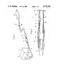
- FIG. 1 is a schematic perspective view of an exhaust system of an internal combustion engine which is furnished with a silencing device in accordance with the present invention
- FIG. 2 is a vertical section of one embodiment of the silencing device.
- FIG. 3 is a plot showing experimental results which proves the reduction of sound pressure level (SPL) attainable with the present invention.
- FIG. 1 of the drawings there are shown an internal combustion engine 1, an exhaust manifold 2 connected to the engine 1, and a catalytic converter 4 connected to the exhaust manifold 2 through an exhaust pipe 3.
- an exhaust pipe 5 Sequentially connected to the catalytic converter 4 are an exhaust pipe 5, a prechamber 6, an exhaust pipe 7, and a muffler 8.
- These parts in combination constitute an exhaust system which is generally designated by the reference numeral 9.
- exhaust gases emanating from the engine 1 are purified by the catalytic converter 4, then silenced by the prechamber 6 and muffler 8, and then discharged to the atmosphere.
- the exhaust pipe 7 extending between the prechamber 6 and the muffler 8 has a substantially uniform section and a sufficient length. As shown in FIG. 2, the exhaust pipe 7 is made up of an inner conduit 10 and an outer conduit 11 which surrounds the inner conduit 10. The outer conduit 11 is provided with radially inwardly extending lugs 12 which are adapted to hold the inner conduit 10 concentrically with and at a substantially constant spacing from the outer tube 11. In this configuration, an annular air gap 13 is defined between the inner conduit 10 and the outer conduit 11.
- the inner conduit 10 of the exhaust pipe 7 protrudes into the prechamber 6, which serves as an expansion chamber, over a sufficient length.
- the outer conduit 11, on the other hand, is contiguous with an inner wall 14 of the prechamber 6 which has a double-wall structure.
- both of the passageway in the inner conduit 10 and the air gap 13 between the inner conduit 10 and outer conduit 11 are fluidly communicated to the prechamber 6.
- the air gap 13 is communicated at one end thereof to the prechamber 6 through an annular opening 15 which is defined between the inner tube 10 and the inner wall 14 of the prechamber 6.
- the exhaust pipe 7 is provide with a radially outwardly extending flange 16 which is connected to the muffler 8.
- the outer conduit 11 is joined with the inner conduit 10 in the vicinity of the flange 16. In this manner, the air gap 13 between the inner conduit 10 and the outer conduit 11 is open at one end into the expansion chamber with which the exhaust pipe 7 is contiguous, while being closed at the other end. Exhaust gases are caused to flow through the interior of the inner conduit 10.
- exhaust gases which are emitted from the engine 1 and purified by the catalytic converter 4 are admitted into the prechamber 6. Because the prechamber 6 plays the role of an expansion chamber, the energy of sound waves of the exhaust gases entered the prechamber 6 interferes with each other and is thereby attenuated while being repeatedly reflected from wall to wall inside of the expansion chamber.
- a part of the sound waves is passed through the opening 15 into the air gap 13 which is defined between the inner conduit 10 and the other conduit 11.
- the air gap 13 which is closed at the other end serves as a resonance chamber, whereby waves opposite in phase to the incoming sound waves are produced.
- the frequency of a wave which is developed in the resonance chamber i.e, the resonance frequency f
- the air gap 13 is sufficiently long because it is provided over substantially the entire length of the exhaust pipe 7. This, coupled with the fact that the opening 15 is positioned inside of the prechamber 6, provides the resonance chamber with an extremely great length l which in turn lowers the resonance frequency f to a significant degree. Stated another way, the resonance chamber is capable of attenuating noise of low frequencies. Further, because the opening 15 is formed over the entire circumference of the inner tube 10 and, therefore, has a sufficiently large area, a considerable amount of attenuation is guaranteed to offer an extra silencing effect.
- the exhaust gases routed through the prechamber 6 and air gap 13 as stated above are fed to the muffler 8 to be further silenced thereby.
- the exhaust pipe 7 has a double-layer structure and partly because the air gap 13 forms an air layer around the inner conduit 10, not only the emission noise is reduced but also the radiation of heat of the exhaust gases to the outside is suppressed.
- FIG. 3 there are shown sound pressure levels measured with the silencing device of the present invention having the above construction and those measured with a prior art silencing device which lacks the air gap, or resonance chamber, 13.
- the measurements were made under an accelerating condition of an engine. It will be seen from FIG. 3 that the device of the invention has a noticeable effect in C characteristic at engine speeds, especially, around 2000 r.p.m, and it was proved that noise whose frequency is as low as 70-80 Hz is remarkably attenuated.
- the exhaust pipe 7 extending between the prechamber 6 and the muffler 8 is provided with a double-layer structure, and the air gap 13 between the inner conduit 10 and the outer conduit 11 is open into the prechamber 6.
- the exhaust pipe 7 may be arranged to extend from the muffler 8 with the air gap 13 opened into the muffler 8, which would then serve as an expansion chamber. In such an alternative arrangement, the air gap 13 would be closed on the prechamber 6 side.
- the catalytic converter 4 plays the role of an expansion chamber.
- the exhaust pipe 3 or 5 which is connected to the converter 4 may be provided with a double-layer structure in order to define a resonance chamber in the above-described manner.
- the exhaust pipe 3 on the upstream side of the converter 4 and provided with a double-layer structure would serve to thermally insulate the exhaust gases flowing therethrough and, thereby, promote catalytic reactions.
Abstract
Description
Claims (3)
Priority Applications (1)
| Application Number | Priority Date | Filing Date | Title |
|---|---|---|---|
| US07/034,961 US4779703A (en) | 1987-04-06 | 1987-04-06 | Silencing device for internal combustion engine |
Applications Claiming Priority (1)
| Application Number | Priority Date | Filing Date | Title |
|---|---|---|---|
| US07/034,961 US4779703A (en) | 1987-04-06 | 1987-04-06 | Silencing device for internal combustion engine |
Publications (1)
| Publication Number | Publication Date |
|---|---|
| US4779703A true US4779703A (en) | 1988-10-25 |
Family
ID=21879738
Family Applications (1)
| Application Number | Title | Priority Date | Filing Date |
|---|---|---|---|
| US07/034,961 Expired - Lifetime US4779703A (en) | 1987-04-06 | 1987-04-06 | Silencing device for internal combustion engine |
Country Status (1)
| Country | Link |
|---|---|
| US (1) | US4779703A (en) |
Cited By (16)
| Publication number | Priority date | Publication date | Assignee | Title |
|---|---|---|---|---|
| EP0714087A3 (en) * | 1994-11-26 | 1996-06-26 | Eberspaecher J | |
| US5800146A (en) * | 1994-12-23 | 1998-09-01 | Sihi Gmbh & Co. Kg | Liquid-ring gas pump with a silencing element in the discharge space |
| US6209319B1 (en) * | 1998-09-28 | 2001-04-03 | Honda Giken Kogyo Kabushiki Kaisha | Pipe assembly having inner and outer pipes |
| US6336471B1 (en) * | 1981-07-16 | 2002-01-08 | James J. Feuling | Flow system for enhancing undirectional fluid flow |
| US20050247516A1 (en) * | 2004-04-01 | 2005-11-10 | Honda Motor Co., Ltd. | Vehicle exhaust system support structure |
| US20070107982A1 (en) * | 2005-11-17 | 2007-05-17 | Sullivan John T | Flow-through sound-cancelling mufflers |
| US20090255519A1 (en) * | 2008-04-14 | 2009-10-15 | Dolmar Gmbh | Silencer for a motor device |
| US20100300799A1 (en) * | 2007-09-06 | 2010-12-02 | Toyota Jidosha Kabushiki Kaisha | Exhaust silencer device for internal combustion engine |
| US20110024228A1 (en) * | 2009-07-31 | 2011-02-03 | Honda Motor Co., Ltd. | Silencer provided on exhaust pipe of vehicle engine |
| US20120241248A1 (en) * | 2011-03-09 | 2012-09-27 | Makita Corporation | Two-stroke engine with a silencer |
| US20130199869A1 (en) * | 2012-02-03 | 2013-08-08 | Honda Motor Co., Ltd. | Exhaust muffler device |
| US20150047922A1 (en) * | 2012-04-02 | 2015-02-19 | Tenneco Gmbh | Muffler having coupling of a tailpipe by means of a coupling chamber |
| CN107023349A (en) * | 2017-05-15 | 2017-08-08 | 江门市大长江集团有限公司 | Motorcycle exhaust pipe and motorcycle |
| CN107489490A (en) * | 2017-09-26 | 2017-12-19 | 奇瑞汽车股份有限公司 | Exhaust silencer |
| CN108374775A (en) * | 2018-02-08 | 2018-08-07 | 合肥富厚机电制造有限公司 | A kind of compressor silencer |
| JP2022095467A (en) * | 2020-12-16 | 2022-06-28 | フタバ産業株式会社 | Exhaust pipe |
Citations (4)
| Publication number | Priority date | Publication date | Assignee | Title |
|---|---|---|---|---|
| US3338331A (en) * | 1965-03-05 | 1967-08-29 | Walker Mfg Co | Exhaust system with plural silencing units |
| US3543878A (en) * | 1969-08-19 | 1970-12-01 | Chrysler Corp | Automobile exhaust muffler |
| US3648803A (en) * | 1969-10-13 | 1972-03-14 | Walker Mfg Co | Exhaust system |
| US3780876A (en) * | 1972-01-18 | 1973-12-25 | Lear Siegler Inc | Shelf divider |
-
1987
- 1987-04-06 US US07/034,961 patent/US4779703A/en not_active Expired - Lifetime
Patent Citations (4)
| Publication number | Priority date | Publication date | Assignee | Title |
|---|---|---|---|---|
| US3338331A (en) * | 1965-03-05 | 1967-08-29 | Walker Mfg Co | Exhaust system with plural silencing units |
| US3543878A (en) * | 1969-08-19 | 1970-12-01 | Chrysler Corp | Automobile exhaust muffler |
| US3648803A (en) * | 1969-10-13 | 1972-03-14 | Walker Mfg Co | Exhaust system |
| US3780876A (en) * | 1972-01-18 | 1973-12-25 | Lear Siegler Inc | Shelf divider |
Cited By (23)
| Publication number | Priority date | Publication date | Assignee | Title |
|---|---|---|---|---|
| US6336471B1 (en) * | 1981-07-16 | 2002-01-08 | James J. Feuling | Flow system for enhancing undirectional fluid flow |
| EP0714087A3 (en) * | 1994-11-26 | 1996-06-26 | Eberspaecher J | |
| US5800146A (en) * | 1994-12-23 | 1998-09-01 | Sihi Gmbh & Co. Kg | Liquid-ring gas pump with a silencing element in the discharge space |
| US6209319B1 (en) * | 1998-09-28 | 2001-04-03 | Honda Giken Kogyo Kabushiki Kaisha | Pipe assembly having inner and outer pipes |
| US20050247516A1 (en) * | 2004-04-01 | 2005-11-10 | Honda Motor Co., Ltd. | Vehicle exhaust system support structure |
| US7458440B2 (en) * | 2004-04-01 | 2008-12-02 | Honda Motor Co., Ltd. | Vehicle exhaust system support structure |
| US20070107982A1 (en) * | 2005-11-17 | 2007-05-17 | Sullivan John T | Flow-through sound-cancelling mufflers |
| US7600607B2 (en) * | 2005-11-17 | 2009-10-13 | John Timothy Sullivan | Flow-through sound-cancelling mufflers |
| US8136627B2 (en) * | 2007-09-06 | 2012-03-20 | Toyota Jidosha Kabushiki Kaisha | Exhaust silencer device for internal combustion engine |
| US20100300799A1 (en) * | 2007-09-06 | 2010-12-02 | Toyota Jidosha Kabushiki Kaisha | Exhaust silencer device for internal combustion engine |
| US20090255519A1 (en) * | 2008-04-14 | 2009-10-15 | Dolmar Gmbh | Silencer for a motor device |
| US8172038B2 (en) * | 2008-04-14 | 2012-05-08 | Dolmar Gmbh | Silencer for a motor device |
| US20110024228A1 (en) * | 2009-07-31 | 2011-02-03 | Honda Motor Co., Ltd. | Silencer provided on exhaust pipe of vehicle engine |
| US8083025B2 (en) * | 2009-07-31 | 2011-12-27 | Honda Motor Co., Ltd. | Silencer provided on exhaust pipe of vehicle engine |
| US20120241248A1 (en) * | 2011-03-09 | 2012-09-27 | Makita Corporation | Two-stroke engine with a silencer |
| US20130199869A1 (en) * | 2012-02-03 | 2013-08-08 | Honda Motor Co., Ltd. | Exhaust muffler device |
| US8807273B2 (en) * | 2012-02-03 | 2014-08-19 | Honda Motor Co., Ltd. | Exhaust muffler device |
| US20150047922A1 (en) * | 2012-04-02 | 2015-02-19 | Tenneco Gmbh | Muffler having coupling of a tailpipe by means of a coupling chamber |
| US9133753B2 (en) * | 2012-04-02 | 2015-09-15 | Tenneco Gmbh | Muffler having coupling of a tailpipe by means of a coupling chamber |
| CN107023349A (en) * | 2017-05-15 | 2017-08-08 | 江门市大长江集团有限公司 | Motorcycle exhaust pipe and motorcycle |
| CN107489490A (en) * | 2017-09-26 | 2017-12-19 | 奇瑞汽车股份有限公司 | Exhaust silencer |
| CN108374775A (en) * | 2018-02-08 | 2018-08-07 | 合肥富厚机电制造有限公司 | A kind of compressor silencer |
| JP2022095467A (en) * | 2020-12-16 | 2022-06-28 | フタバ産業株式会社 | Exhaust pipe |
Similar Documents
| Publication | Publication Date | Title |
|---|---|---|
| US4779703A (en) | Silencing device for internal combustion engine | |
| US5365025A (en) | Low backpressure straight-through reactive and dissipative muffler | |
| US6199658B1 (en) | Multi-Fold side branch muffler | |
| US5828013A (en) | Muffler with catalytic converter arrangement; and method | |
| US5426269A (en) | Muffler with catalytic converter arrangement; and method | |
| JPH073170B2 (en) | Exhaust gas muffler | |
| JPH08114117A (en) | Exhausting device for vehicle | |
| US2520756A (en) | Exhaust silencer for internalcombustion engines | |
| US6595319B1 (en) | Muffler | |
| US3072214A (en) | Gas blending and sound-attenuating system and apparatus | |
| JPS63138110A (en) | Exhaust manifold | |
| CA1083486A (en) | Louver flow muffler | |
| US3104732A (en) | Acoustically treated gas pipe | |
| EP0542749B1 (en) | Noise cancellation apparatus | |
| JP2004519575A (en) | Device for damping resonance in conduit | |
| CA1070617A (en) | Exhaust muffler having an attenuater can assembly | |
| JP2515905Y2 (en) | Silencer | |
| US3447629A (en) | Automotive exhaust system and muffler therefor | |
| JP3078253B2 (en) | Silencer for internal combustion engine | |
| JPH0523770Y2 (en) | ||
| JPS6221702Y2 (en) | ||
| CN216043947U (en) | Muffler for vehicle exhaust system | |
| US3989121A (en) | Pulse converting exhaust silencing system | |
| JPS62291413A (en) | Exhaust muffler | |
| JPS636406Y2 (en) |
Legal Events
| Date | Code | Title | Description |
|---|---|---|---|
| AS | Assignment |
Owner name: HONDA GIKEN KOGYO KABUSHIKI KAISHA, 2-1-1, MINAMI- Free format text: ASSIGNMENT OF ASSIGNORS INTEREST.;ASSIGNORS:TAKIGUCHI, SHIRO;TAKAHASHI, ISAO;KAWAKAMI, HIROO;AND OTHERS;REEL/FRAME:004695/0321 Effective date: 19870320 Owner name: SANKEI GIKEN KOGYO KABUSHIKI KAISHA, 2-5-1, AKABAN Free format text: ASSIGNMENT OF ASSIGNORS INTEREST.;ASSIGNORS:TAKIGUCHI, SHIRO;TAKAHASHI, ISAO;KAWAKAMI, HIROO;AND OTHERS;REEL/FRAME:004695/0321 Effective date: 19870320 |
|
| STCF | Information on status: patent grant |
Free format text: PATENTED CASE |
|
| FEPP | Fee payment procedure |
Free format text: PAYOR NUMBER ASSIGNED (ORIGINAL EVENT CODE: ASPN); ENTITY STATUS OF PATENT OWNER: LARGE ENTITY |
|
| FPAY | Fee payment |
Year of fee payment: 4 |
|
| FPAY | Fee payment |
Year of fee payment: 8 |
|
| FPAY | Fee payment |
Year of fee payment: 12 |