EP0641943B1 - Nutenstein - Google Patents
Nutenstein Download PDFInfo
- Publication number
- EP0641943B1 EP0641943B1 EP94110921A EP94110921A EP0641943B1 EP 0641943 B1 EP0641943 B1 EP 0641943B1 EP 94110921 A EP94110921 A EP 94110921A EP 94110921 A EP94110921 A EP 94110921A EP 0641943 B1 EP0641943 B1 EP 0641943B1
- Authority
- EP
- European Patent Office
- Prior art keywords
- base part
- clamping
- tenon block
- bore
- wedge
- Prior art date
- Legal status (The legal status is an assumption and is not a legal conclusion. Google has not performed a legal analysis and makes no representation as to the accuracy of the status listed.)
- Expired - Lifetime
Links
- 229920002994 synthetic fiber Polymers 0.000 claims 5
- 239000004033 plastic Substances 0.000 abstract description 17
- 229920006324 polyoxymethylene Polymers 0.000 description 3
- 229930182556 Polyacetal Natural products 0.000 description 2
- 239000004952 Polyamide Substances 0.000 description 2
- 229910000831 Steel Inorganic materials 0.000 description 2
- 238000006073 displacement reaction Methods 0.000 description 2
- 238000004519 manufacturing process Methods 0.000 description 2
- 239000002184 metal Substances 0.000 description 2
- 229920002647 polyamide Polymers 0.000 description 2
- 239000010959 steel Substances 0.000 description 2
- 238000004026 adhesive bonding Methods 0.000 description 1
- 230000015572 biosynthetic process Effects 0.000 description 1
- 230000006835 compression Effects 0.000 description 1
- 238000007906 compression Methods 0.000 description 1
- 238000002347 injection Methods 0.000 description 1
- 239000007924 injection Substances 0.000 description 1
- 238000007493 shaping process Methods 0.000 description 1
Images
Classifications
-
- F—MECHANICAL ENGINEERING; LIGHTING; HEATING; WEAPONS; BLASTING
- F16—ENGINEERING ELEMENTS AND UNITS; GENERAL MEASURES FOR PRODUCING AND MAINTAINING EFFECTIVE FUNCTIONING OF MACHINES OR INSTALLATIONS; THERMAL INSULATION IN GENERAL
- F16B—DEVICES FOR FASTENING OR SECURING CONSTRUCTIONAL ELEMENTS OR MACHINE PARTS TOGETHER, e.g. NAILS, BOLTS, CIRCLIPS, CLAMPS, CLIPS OR WEDGES; JOINTS OR JOINTING
- F16B37/00—Nuts or like thread-engaging members
- F16B37/04—Devices for fastening nuts to surfaces, e.g. sheets, plates
- F16B37/045—Devices for fastening nuts to surfaces, e.g. sheets, plates specially adapted for fastening in channels, e.g. sliding bolts, channel nuts
- F16B37/046—Devices for fastening nuts to surfaces, e.g. sheets, plates specially adapted for fastening in channels, e.g. sliding bolts, channel nuts with resilient means for urging the nut inside the channel
-
- F—MECHANICAL ENGINEERING; LIGHTING; HEATING; WEAPONS; BLASTING
- F16—ENGINEERING ELEMENTS AND UNITS; GENERAL MEASURES FOR PRODUCING AND MAINTAINING EFFECTIVE FUNCTIONING OF MACHINES OR INSTALLATIONS; THERMAL INSULATION IN GENERAL
- F16B—DEVICES FOR FASTENING OR SECURING CONSTRUCTIONAL ELEMENTS OR MACHINE PARTS TOGETHER, e.g. NAILS, BOLTS, CIRCLIPS, CLAMPS, CLIPS OR WEDGES; JOINTS OR JOINTING
- F16B33/00—Features common to bolt and nut
- F16B33/006—Non-metallic fasteners using screw-thread
-
- Y—GENERAL TAGGING OF NEW TECHNOLOGICAL DEVELOPMENTS; GENERAL TAGGING OF CROSS-SECTIONAL TECHNOLOGIES SPANNING OVER SEVERAL SECTIONS OF THE IPC; TECHNICAL SUBJECTS COVERED BY FORMER USPC CROSS-REFERENCE ART COLLECTIONS [XRACs] AND DIGESTS
- Y10—TECHNICAL SUBJECTS COVERED BY FORMER USPC
- Y10T—TECHNICAL SUBJECTS COVERED BY FORMER US CLASSIFICATION
- Y10T403/00—Joints and connections
- Y10T403/71—Rod side to plate or side
- Y10T403/7117—Flanged or grooved rod
Definitions
- the invention relates to a sliding block with the Features specified in the preamble of claim 1.
- a sliding block with the features mentioned above is known from DE-A-1 923 669.
- the well-known sliding block has trapezoidal cross section and longitudinal slots so that it is in undercut grooves can be pressed and then under Support snaps onto the profile groove floor.
- Edges of the sliding block are essentially different Spring bracket arms extending over the entire edge length present, which the slot nut approximately at the level of the central Support the threaded screw hole.
- Such a sliding block is not suitable for slim grooves.
- Sliding blocks of a similar type are from the EP 0 136 431 known. They are generally used for screw fastening of those provided with such undercut grooves Profile rods or the like components to be attached via a screw to be screwed into the screw hole of the sliding block Fastening screw are fixed using the sliding block with the edges of its flat top firmly against the underside of the profile groove slot flanking on both sides Profile grooved leg is pressed.
- the sliding block does not have to have a wedge-shaped cross-section must be inserted laterally into the profile groove. Rather, it can be anywhere on the profile bar be easily swung into the profile groove, being in the relevant axial position in the profile groove by the on its Clamping point lying on the floor can be kept slightly clamped can.
- the invention is therefore based on the object Sliding block with the features of the preamble of the claim to improve so that it is essential is easier and cheaper to manufacture.
- This task is based on a sliding block in The genus in question solved according to the invention in that a spring clip arm in the area of a wedge apex line pivotable sliding block is arranged as well as on his free, resilient end has the clamping point, and that the screw threaded bore outside of one of the Longitudinal slot formed area is arranged.
- a spring clip arm in the area of a wedge apex line pivotable sliding block is arranged as well as on his free, resilient end has the clamping point, and that the screw threaded bore outside of one of the Longitudinal slot formed area is arranged.
- the sliding block can be according to a further feature of the invention a base part having the wedge-shaped cross section have made of plastic, which is approximately in the longitudinal direction divided in half, on the one hand that for shaping the spring arm fork area provided with the longitudinal slot and on the other hand, one with a screw thread bore containing metallic insert sleeve provided bore receiving area having.
- the aforementioned plastic base part that from correspondingly hard elastic plastic, for example Polyamide or one also under the short name POM known polyacetal, can be injection molded easily manufactured, then in the base part so shaped only the one that contains the threaded screw hole metallic insert sleeve needs to be used. That's what the plastic base part is for preferably in its bore receiving area with a continuous, the metallic insert sleeve containing receiving bore and one arranged above it shallow recess on which the with a corresponding insert flange provided lies on.
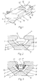
- the sliding block shown is of two parts. It consists of one essentially wedge-shaped Cross-section plastic base part 1 and the in this used metallic insert sleeve 2, with a Screw threaded hole 3 is provided.
- a polyacetal base part 1 is approximately half in the longitudinal direction in two different Areas divided. So it has a fork area la on the one hand and a bore receiving area 1b on the other hand.
- a longitudinal slot 4 is provided for Formation of the wedge apex line 1 'in the longitudinal direction of the base part 1 extending spring arm 5 is used, the its free end 5 'a molded on the underside Has terminal point 6 forming clamp button.
- this clamp button is the sliding block 1 in its in Fig.2 and 3 in the Profile groove 7 of a profile bar 8 or the like.
- the plastic base part has in the bore receiving area 1b 1, as shown in FIG. 3, a receiving bore 9 for the therein used, preferably made of deep-drawing steel Insert sleeve 2, which contains the threaded screw hole 3.
- the Insert sleeve 2 has a rectangular contour Edge flange 2 'with which they are on a above the mounting hole 9 located recess 10 rests in the plastic base part 1.
- the plastic base part 1 is on its top with on both sides of the screw hole 3 containing metallic insert sleeve 2 located, molded Provide projections 11, 12, which correspond to the profile groove 7 Fig. 2 and 3 pivoted sliding block in the protrude outside slot 7 '' 'of the profile groove 7 and thereby ensure sufficient security against rotation.
- the projections 11 and 12 can continue on their insert sleeve 2 facing edges 11 'and 12' also slightly have projecting clamping edges that over the corresponding Grab edges of the edge flange 2 'of the insert sleeve 2. This results in a simple clamp fastening of the insert sleeve 2 in the plastic base part 1. But it goes without saying that a such clamp attachment can also be achieved in other ways can.
- the insert sleeve 2 in the base part 1 can just as well be glued.
Landscapes
- Engineering & Computer Science (AREA)
- General Engineering & Computer Science (AREA)
- Mechanical Engineering (AREA)
- Clamps And Clips (AREA)
- Pens And Brushes (AREA)
- Superconductors And Manufacturing Methods Therefor (AREA)
- Glass Compositions (AREA)
- Dowels (AREA)
- Furniture Connections (AREA)
- Waveguide Aerials (AREA)
- Heat Treatment Of Strip Materials And Filament Materials (AREA)
- Turbine Rotor Nozzle Sealing (AREA)
- Materials For Medical Uses (AREA)
- Dental Preparations (AREA)
- Mutual Connection Of Rods And Tubes (AREA)
Description
- Fig.1
- eine schaubildliche Wiedergabe des Nutensteins,
- Fig.2
- eine Stirnansicht des in eine Profilnut eines geschnitten dargestellten Profilstabes eingesetzten Nutensteines und
- Fig.3
- eine der Fig.2 entsprechende Darstellung, jedoch im Schnitt nach der Linie III-III der Fig.1.
Claims (6)
- In T-förmig hinterschnittene Nuten (7) von Profilstäben (8) od.dgl. einsetzbarer Nutenstein mit einem im wesentlichen keilförmigen Querschnitt, mit einem aus Kunststoff bestehenden, von einem Längsschlitz (4) gebildeten Federbügelarm (5), der sich in Längsrichtung des Nutensteins erstreckt und eine Klemmstelle (6) aufweist, und mit einer senkrecht zum Längsschlitz (4) verlaufenden Schraubgewindebohrung (3), dadurch gekennzeichnet, daß der Federbügelarm (5) im Bereich einer Keilscheitellinie (1') des in die Nut einschwenkbaren Nutensteins angeordnet ist sowie an seinem freien, federnd nachgiebigen Ende (5') die Klemmstelle aufweist (5), und daß die Schraubgewindebohrung (3) außerhalb eines von dem Längsschlitz (4) gebildeten Bereichs (la) angeordnet ist.
- Nutenstein nach Anspruch 1, dadurch gekennzeichnet, daß die Klemmstelle (6) aus einem am freien Ende (5') des Kunststoff-Federbügelarms (5) unterseitig angeformten Klemmknopf besteht.
- Nutenstein nach Anspruch 1 oder 2, dadurch gekennzeichnet, daß er ein den keilförmigen Querschnitt besitzendes Basisteil (1) aus Kunststoff aufweist, das in Längsrichtung etwa hälftig unterteilt, einerseits den zur Ausformung des Federbügelarms (5) mit dem Längsschlitz (4) versehenen Gabelbereich (la) und andererseits einen mit einer die Schraubgewindebohrung (3) enthaltenden, metallischen Einlagebüchse (2) versehenen Bohrungsaufnahmebereich (1b) aufweist.
- Nutenstein nach Anspruch 3, dadurch gekennzeichnet, daß das Kunststoff-Basisteil (1) in seinem Bohrungsaufnahmebereich (1b) mit einer durchgehenden, die metallische Einlagebüchse (2) enthaltenden Aufnahmebohrung (9) und einer oberhalb davon angeordneten flachen Aussparung (10) versehen ist, auf der die mit einem entsprechenden Randflansch (2') versehene metallische Einlagebüchse (2) aufliegt.
- Nutenstein nach Anspruch 4, dadurch gekennzeichnet, daß auf der Oberseite des Kunststoff-Basisteils (1) zu beiden Seiten der die Schraubgewindebohrung (3) enthaltenden metallischen Einlagebüchse (2) verdrehungssichernde Vorsprünge (11,12) angeformt sind.
- Nutenstein nach Anspruch 5, dadurch gekennzeichnet, daß der an der metallischen Einlagebüchse (2) vorhandene Randflansch (2') rechteckförmig konturiert ist und an den ihm zugewandten Rändern (11',12') der verdrehungssichernden Vorsprünge (11,12) des Basisteils (1) Klemmkanten vorgesehen sind, die leicht klemmend über die entsprechenden Kanten des Randflansches (2') greifen.
Applications Claiming Priority (2)
| Application Number | Priority Date | Filing Date | Title |
|---|---|---|---|
| DE9312997U | 1993-08-30 | ||
| DE9312997U DE9312997U1 (de) | 1993-08-30 | 1993-08-30 | Nutenstein |
Publications (2)
| Publication Number | Publication Date |
|---|---|
| EP0641943A1 EP0641943A1 (de) | 1995-03-08 |
| EP0641943B1 true EP0641943B1 (de) | 1998-12-02 |
Family
ID=6897417
Family Applications (1)
| Application Number | Title | Priority Date | Filing Date |
|---|---|---|---|
| EP94110921A Expired - Lifetime EP0641943B1 (de) | 1993-08-30 | 1994-07-13 | Nutenstein |
Country Status (8)
| Country | Link |
|---|---|
| US (1) | US6062764A (de) |
| EP (1) | EP0641943B1 (de) |
| JP (1) | JPH0783223A (de) |
| AT (1) | ATE174107T1 (de) |
| DE (2) | DE9312997U1 (de) |
| DK (1) | DK0641943T3 (de) |
| ES (1) | ES2127315T3 (de) |
| GR (1) | GR3029409T3 (de) |
Cited By (1)
| Publication number | Priority date | Publication date | Assignee | Title |
|---|---|---|---|---|
| EP2169775A1 (de) | 2008-09-24 | 2010-03-31 | Harting Electronics GmbH & Co. KG | Symmetrischer elektrischer Kontakt |
Families Citing this family (20)
| Publication number | Priority date | Publication date | Assignee | Title |
|---|---|---|---|---|
| ATE213526T1 (de) * | 1996-05-23 | 2002-03-15 | Oliver Wanke | Befestigungselement für den einsatz in hinterschnittene profilnuten |
| CA2371667A1 (en) | 2002-02-14 | 2003-08-14 | Taylor Manufacturing Industries Inc. | Connecting device for modular frame construction |
| DE10353702A1 (de) * | 2003-11-18 | 2005-06-16 | Valeo Klimasysteme Gmbh | Befestigungsmittelaufnahmevorrichtung |
| US20090078425A1 (en) * | 2007-09-25 | 2009-03-26 | Seahorse Equipment Corp | Flexible hang-off arrangement for a catenary riser |
| US8182023B2 (en) | 2010-03-16 | 2012-05-22 | Sabic Innovative Plastics Ip B.V. | Plastically deformable spring energy management systems and methods for making and using the same |
| US8607710B2 (en) | 2010-10-28 | 2013-12-17 | Jack Farr | Cable-tow system having a stationary support cable |
| DE102011078445A1 (de) * | 2011-06-30 | 2013-01-03 | Wto Werkzeug-Einrichtungen Gmbh | Werkzeugträger mit auswechselbaren Werkzeughaltern und Werkzeughalter |
| CN202280709U (zh) * | 2011-11-11 | 2012-06-20 | 林博贤 | 一种旋扣式榫接结构以及具有该榫接结构的家具 |
| US10619791B2 (en) | 2013-03-14 | 2020-04-14 | Eaton Intelligent Power Limited | Channel framing with additional functional side |
| CA2875556C (en) | 2013-12-23 | 2022-07-12 | Cooper Technologies Company | Fastener nut for channel framing |
| CA2889176C (en) | 2014-04-30 | 2022-08-16 | Cooper Technologies Company | Trapeze hanger system including trapeze hanger fitting |
| CA2890064C (en) | 2014-04-30 | 2022-08-16 | Cooper Technologies Company | Trapeze hanger system including twist-locking fitting |
| CA2889880C (en) | 2014-05-02 | 2022-05-31 | Cooper Technologies Company | Conduit clamp for strut channel |
| CA2889168C (en) * | 2014-05-02 | 2022-09-20 | Cooper Technologies Company | Strut system and strut fitting therefor |
| TWI593616B (zh) * | 2014-06-27 | 2017-08-01 | 巴柏斯特麥克斯合資公司 | 用於將板片元件供給至機器的方法,供給平台以及裝備該供給平台的加工機 |
| US10100861B2 (en) | 2014-11-14 | 2018-10-16 | Cooper Technologies Company | Beam clamp for strut channel |
| US9926957B2 (en) | 2014-11-14 | 2018-03-27 | Cooper Technologies Company | Fitting for strut channel |
| US9982695B2 (en) | 2014-11-14 | 2018-05-29 | Cooper Technologies Company | Fitting for strut channel |
| US9347213B1 (en) | 2014-11-14 | 2016-05-24 | Cooper Technologies Company | Fitting for channel framing |
| JP6016981B1 (ja) * | 2015-05-19 | 2016-10-26 | 株式会社青山製作所 | ケースナット |
Citations (1)
| Publication number | Priority date | Publication date | Assignee | Title |
|---|---|---|---|---|
| EP0136431A2 (de) * | 1983-08-04 | 1985-04-10 | Item Industrietechnik und Maschinenbau GmbH | Konstruktion aus Profilstäben |
Family Cites Families (14)
| Publication number | Priority date | Publication date | Assignee | Title |
|---|---|---|---|---|
| FR1333810A (fr) * | 1962-05-29 | 1963-08-02 | Acec | Bâti de fixation pour appareils divers |
| US3321813A (en) * | 1964-12-11 | 1967-05-30 | United Carr Inc | Combination metal and plastic members |
| FR1546776A (fr) * | 1967-10-12 | 1968-11-22 | Entpr Ind L | Dispositif de maintien d'un écrou dans un profilé |
| AT314011B (de) * | 1968-05-10 | 1974-03-11 | Tuflex Ag | Verankerungsvorrichtung zum lösbaren Befestigen von Gegenständen an einer Hohlprofilschiene mit etwa C-förmigem Querschnitt |
| DE1996313U (de) * | 1968-07-19 | 1968-11-07 | Niedax Gmbh | Gleitmutter |
| DE6750452U (de) * | 1968-07-27 | 1969-01-09 | Christian Geyer Elektrotechn F | Zaehlertafel |
| US4741582A (en) * | 1982-09-30 | 1988-05-03 | Lafrance Corporation | Mounting fastener |
| US4758124A (en) * | 1985-10-08 | 1988-07-19 | Ingeberg Bjoern | Arrangement relating to a nut for location in an open channel section |
| DE3604989A1 (de) * | 1986-02-17 | 1987-08-20 | Rose & Krieger Gmbh Co Kg | Vorrichtung zum loesbaren verbinden zweier profilstaebe |
| FR2638796B1 (fr) * | 1989-03-29 | 1991-02-15 | Shur Lok International Sa | Dispositif d'assemblage a ecrou-barillet flottant |
| DE4016320C1 (de) * | 1990-05-21 | 1991-09-19 | Wolfgang Dipl.-Ing. Rixen | |
| CH682004A5 (de) * | 1990-06-15 | 1993-06-30 | Alusuisse Lonza Services Ag | |
| GB9111647D0 (en) * | 1991-05-30 | 1991-07-24 | Unistrut Europ | Improvements in or relating to channel fixing devices |
| DE9111163U1 (de) * | 1991-09-09 | 1991-11-21 | Jost, Peter, Dipl.-Ing., 3260 Rinteln, De |
-
1993
- 1993-08-30 DE DE9312997U patent/DE9312997U1/de not_active Expired - Lifetime
-
1994
- 1994-07-13 AT AT94110921T patent/ATE174107T1/de not_active IP Right Cessation
- 1994-07-13 ES ES94110921T patent/ES2127315T3/es not_active Expired - Lifetime
- 1994-07-13 EP EP94110921A patent/EP0641943B1/de not_active Expired - Lifetime
- 1994-07-13 DE DE59407375T patent/DE59407375D1/de not_active Expired - Lifetime
- 1994-07-13 DK DK94110921T patent/DK0641943T3/da active
- 1994-08-26 US US08/296,701 patent/US6062764A/en not_active Expired - Fee Related
- 1994-08-29 JP JP6203274A patent/JPH0783223A/ja active Pending
-
1999
- 1999-02-16 GR GR990400491T patent/GR3029409T3/el unknown
Patent Citations (1)
| Publication number | Priority date | Publication date | Assignee | Title |
|---|---|---|---|---|
| EP0136431A2 (de) * | 1983-08-04 | 1985-04-10 | Item Industrietechnik und Maschinenbau GmbH | Konstruktion aus Profilstäben |
Cited By (1)
| Publication number | Priority date | Publication date | Assignee | Title |
|---|---|---|---|---|
| EP2169775A1 (de) | 2008-09-24 | 2010-03-31 | Harting Electronics GmbH & Co. KG | Symmetrischer elektrischer Kontakt |
Also Published As
| Publication number | Publication date |
|---|---|
| DE9312997U1 (de) | 1995-01-05 |
| ATE174107T1 (de) | 1998-12-15 |
| US6062764A (en) | 2000-05-16 |
| JPH0783223A (ja) | 1995-03-28 |
| DK0641943T3 (da) | 1999-08-16 |
| ES2127315T3 (es) | 1999-04-16 |
| EP0641943A1 (de) | 1995-03-08 |
| DE59407375D1 (de) | 1999-01-14 |
| GR3029409T3 (en) | 1999-05-28 |
Similar Documents
| Publication | Publication Date | Title |
|---|---|---|
| EP0641943B1 (de) | Nutenstein | |
| DE10329518B4 (de) | Führungseinrichtung für eine Schiebetür | |
| DE2133639A1 (de) | Schreibstiftgehause | |
| EP0849421A1 (de) | Türdrücker mit Metalloberfläche | |
| EP0030712A1 (de) | Zirkel | |
| DE3421763C2 (de) | ||
| DE19532933A1 (de) | Schließvorrichtung | |
| EP0898658B1 (de) | Befestigungselement für den einsatz in hinterschnittene profilnuten | |
| WO1991011939A1 (de) | Halteblock für konsolen | |
| DE7403713U (de) | Türschild oder Rosette | |
| DE3438854A1 (de) | Verbindungsbeschlag fuer moebelteile | |
| DE4117565C2 (de) | Handschreibgerät mit Halteklipp | |
| DE3223554A1 (de) | Zierleiste od. dgl., insbesondere fuer fahrzeuge | |
| CH675980A5 (de) | ||
| DE10002052A1 (de) | Clipbefestigung eines Schreibgeräts | |
| DE3118390A1 (de) | Schreibfeder und fuellhalter dafuer | |
| DE8331968U1 (de) | Verbindungsvorrichtung fuer moebelwandungen | |
| DE2234440C3 (de) | Klapplager für Sonnenblenden | |
| DE7910098U1 (de) | Gehaeuse fuer eine fahrradglocke | |
| DE2743803A1 (de) | Schreibgeraet | |
| DE8602293U1 (de) | Bilderrahmenklammer | |
| DE1217142B (de) | Befestigungselement | |
| DE20011975U1 (de) | Pfosten für Geländer von Treppen und Brüstungen | |
| DE2602301A1 (de) | Druckbleistift fuer duenne minen | |
| DE2437052B2 (de) | Türpuffer |
Legal Events
| Date | Code | Title | Description |
|---|---|---|---|
| PUAI | Public reference made under article 153(3) epc to a published international application that has entered the european phase |
Free format text: ORIGINAL CODE: 0009012 |
|
| AK | Designated contracting states |
Kind code of ref document: A1 Designated state(s): AT BE CH DE DK ES FR GB GR IT LI NL SE |
|
| 17P | Request for examination filed |
Effective date: 19950513 |
|
| 17Q | First examination report despatched |
Effective date: 19960823 |
|
| GRAG | Despatch of communication of intention to grant |
Free format text: ORIGINAL CODE: EPIDOS AGRA |
|
| GRAG | Despatch of communication of intention to grant |
Free format text: ORIGINAL CODE: EPIDOS AGRA |
|
| GRAH | Despatch of communication of intention to grant a patent |
Free format text: ORIGINAL CODE: EPIDOS IGRA |
|
| GRAH | Despatch of communication of intention to grant a patent |
Free format text: ORIGINAL CODE: EPIDOS IGRA |
|
| GRAA | (expected) grant |
Free format text: ORIGINAL CODE: 0009210 |
|
| AK | Designated contracting states |
Kind code of ref document: B1 Designated state(s): AT BE CH DE DK ES FR GB GR IT LI NL SE |
|
| REF | Corresponds to: |
Ref document number: 174107 Country of ref document: AT Date of ref document: 19981215 Kind code of ref document: T |
|
| REG | Reference to a national code |
Ref country code: CH Ref legal event code: EP |
|
| REF | Corresponds to: |
Ref document number: 59407375 Country of ref document: DE Date of ref document: 19990114 |
|
| GBT | Gb: translation of ep patent filed (gb section 77(6)(a)/1977) |
Effective date: 19990118 |
|
| REG | Reference to a national code |
Ref country code: CH Ref legal event code: NV Representative=s name: E. BLUM & CO. PATENTANWAELTE |
|
| ITF | It: translation for a ep patent filed |
Owner name: STUDIO TORTA S.R.L. |
|
| ET | Fr: translation filed | ||
| REG | Reference to a national code |
Ref country code: ES Ref legal event code: FG2A Ref document number: 2127315 Country of ref document: ES Kind code of ref document: T3 |
|
| REG | Reference to a national code |
Ref country code: DK Ref legal event code: T3 |
|
| PLBE | No opposition filed within time limit |
Free format text: ORIGINAL CODE: 0009261 |
|
| STAA | Information on the status of an ep patent application or granted ep patent |
Free format text: STATUS: NO OPPOSITION FILED WITHIN TIME LIMIT |
|
| 26N | No opposition filed | ||
| REG | Reference to a national code |
Ref country code: GB Ref legal event code: IF02 |
|
| REG | Reference to a national code |
Ref country code: CH Ref legal event code: PFA Owner name: RIXEN, WOLFGANG, DIPL.-ING. Free format text: RIXEN, WOLFGANG, DIPL.-ING.#FRIEDENSTRASSE 107-109#42699 SOLINGEN (DE) $ PIES, GERRIT#FRIEDENSTRASSE 107-109#42699 SOLINGEN (DE) -TRANSFER TO- RIXEN, WOLFGANG, DIPL.-ING.#FRIEDENSTRASSE 107-109#42699 SOLINGEN (DE) $ PIES, GERRIT#FRIEDENSTRASSE 107-109#42699 SOLINGEN (DE) |
|
| PGFP | Annual fee paid to national office [announced via postgrant information from national office to epo] |
Ref country code: ES Payment date: 20090724 Year of fee payment: 16 Ref country code: DK Payment date: 20090714 Year of fee payment: 16 |
|
| PGFP | Annual fee paid to national office [announced via postgrant information from national office to epo] |
Ref country code: SE Payment date: 20090715 Year of fee payment: 16 Ref country code: NL Payment date: 20090730 Year of fee payment: 16 |
|
| PGFP | Annual fee paid to national office [announced via postgrant information from national office to epo] |
Ref country code: BE Payment date: 20090818 Year of fee payment: 16 |
|
| PGFP | Annual fee paid to national office [announced via postgrant information from national office to epo] |
Ref country code: IT Payment date: 20090723 Year of fee payment: 16 |
|
| PGFP | Annual fee paid to national office [announced via postgrant information from national office to epo] |
Ref country code: GR Payment date: 20090730 Year of fee payment: 16 |
|
| PGFP | Annual fee paid to national office [announced via postgrant information from national office to epo] |
Ref country code: CH Payment date: 20100726 Year of fee payment: 17 |
|
| PGFP | Annual fee paid to national office [announced via postgrant information from national office to epo] |
Ref country code: FR Payment date: 20100805 Year of fee payment: 17 Ref country code: AT Payment date: 20100714 Year of fee payment: 17 |
|
| PGFP | Annual fee paid to national office [announced via postgrant information from national office to epo] |
Ref country code: GB Payment date: 20100722 Year of fee payment: 17 |
|
| BERE | Be: lapsed |
Owner name: *PIES GERRIT Effective date: 20100731 Owner name: *RIXEN WOLFGANG Effective date: 20100731 |
|
| REG | Reference to a national code |
Ref country code: NL Ref legal event code: V1 Effective date: 20110201 |
|
| PGFP | Annual fee paid to national office [announced via postgrant information from national office to epo] |
Ref country code: DE Payment date: 20100928 Year of fee payment: 17 |
|
| PG25 | Lapsed in a contracting state [announced via postgrant information from national office to epo] |
Ref country code: IT Free format text: LAPSE BECAUSE OF NON-PAYMENT OF DUE FEES Effective date: 20100713 Ref country code: NL Free format text: LAPSE BECAUSE OF NON-PAYMENT OF DUE FEES Effective date: 20110201 |
|
| PG25 | Lapsed in a contracting state [announced via postgrant information from national office to epo] |
Ref country code: GR Free format text: LAPSE BECAUSE OF NON-PAYMENT OF DUE FEES Effective date: 20110202 Ref country code: BE Free format text: LAPSE BECAUSE OF NON-PAYMENT OF DUE FEES Effective date: 20100731 |
|
| REG | Reference to a national code |
Ref country code: ES Ref legal event code: FD2A Effective date: 20110818 |
|
| REG | Reference to a national code |
Ref country code: DK Ref legal event code: EBP |
|
| PG25 | Lapsed in a contracting state [announced via postgrant information from national office to epo] |
Ref country code: ES Free format text: LAPSE BECAUSE OF NON-PAYMENT OF DUE FEES Effective date: 20100714 |
|
| REG | Reference to a national code |
Ref country code: CH Ref legal event code: PL |
|
| GBPC | Gb: european patent ceased through non-payment of renewal fee |
Effective date: 20110713 |
|
| REG | Reference to a national code |
Ref country code: AT Ref legal event code: MM01 Ref document number: 174107 Country of ref document: AT Kind code of ref document: T Effective date: 20110713 |
|
| REG | Reference to a national code |
Ref country code: FR Ref legal event code: ST Effective date: 20120330 |
|
| PG25 | Lapsed in a contracting state [announced via postgrant information from national office to epo] |
Ref country code: FR Free format text: LAPSE BECAUSE OF NON-PAYMENT OF DUE FEES Effective date: 20110801 Ref country code: DE Free format text: LAPSE BECAUSE OF NON-PAYMENT OF DUE FEES Effective date: 20120201 Ref country code: CH Free format text: LAPSE BECAUSE OF NON-PAYMENT OF DUE FEES Effective date: 20110731 Ref country code: LI Free format text: LAPSE BECAUSE OF NON-PAYMENT OF DUE FEES Effective date: 20110731 |
|
| REG | Reference to a national code |
Ref country code: DE Ref legal event code: R119 Ref document number: 59407375 Country of ref document: DE Effective date: 20120201 |
|
| PG25 | Lapsed in a contracting state [announced via postgrant information from national office to epo] |
Ref country code: GB Free format text: LAPSE BECAUSE OF NON-PAYMENT OF DUE FEES Effective date: 20110713 |
|
| PG25 | Lapsed in a contracting state [announced via postgrant information from national office to epo] |
Ref country code: DK Free format text: LAPSE BECAUSE OF NON-PAYMENT OF DUE FEES Effective date: 20100802 |
|
| PG25 | Lapsed in a contracting state [announced via postgrant information from national office to epo] |
Ref country code: SE Free format text: LAPSE BECAUSE OF NON-PAYMENT OF DUE FEES Effective date: 20100714 |
|
| PG25 | Lapsed in a contracting state [announced via postgrant information from national office to epo] |
Ref country code: AT Free format text: LAPSE BECAUSE OF NON-PAYMENT OF DUE FEES Effective date: 20110713 |
|
| REG | Reference to a national code |
Ref country code: GR Ref legal event code: ML Ref document number: 990400491 Country of ref document: GR Effective date: 20110202 |