EP0638706A1 - Valve actuating mechanism of an internal combustion engine - Google Patents
Valve actuating mechanism of an internal combustion engine Download PDFInfo
- Publication number
- EP0638706A1 EP0638706A1 EP93119520A EP93119520A EP0638706A1 EP 0638706 A1 EP0638706 A1 EP 0638706A1 EP 93119520 A EP93119520 A EP 93119520A EP 93119520 A EP93119520 A EP 93119520A EP 0638706 A1 EP0638706 A1 EP 0638706A1
- Authority
- EP
- European Patent Office
- Prior art keywords
- rocker arm
- cam
- valve
- lift
- valve train
- Prior art date
- Legal status (The legal status is an assumption and is not a legal conclusion. Google has not performed a legal analysis and makes no representation as to the accuracy of the status listed.)
- Withdrawn
Links
- 238000002485 combustion reaction Methods 0.000 title claims abstract description 18
- 230000005540 biological transmission Effects 0.000 claims abstract description 31
- 238000005096 rolling process Methods 0.000 claims description 7
- 230000006835 compression Effects 0.000 description 3
- 238000007906 compression Methods 0.000 description 3
- 238000010276 construction Methods 0.000 description 3
- 230000008878 coupling Effects 0.000 description 2
- 238000010168 coupling process Methods 0.000 description 2
- 238000005859 coupling reaction Methods 0.000 description 2
- 238000010586 diagram Methods 0.000 description 2
- 238000011161 development Methods 0.000 description 1
- 230000018109 developmental process Effects 0.000 description 1
- 238000006073 displacement reaction Methods 0.000 description 1
- 230000000630 rising effect Effects 0.000 description 1
- 239000013585 weight reducing agent Substances 0.000 description 1
Images


Classifications
-
- F—MECHANICAL ENGINEERING; LIGHTING; HEATING; WEAPONS; BLASTING
- F01—MACHINES OR ENGINES IN GENERAL; ENGINE PLANTS IN GENERAL; STEAM ENGINES
- F01L—CYCLICALLY OPERATING VALVES FOR MACHINES OR ENGINES
- F01L13/00—Modifications of valve-gear to facilitate reversing, braking, starting, changing compression ratio, or other specific operations
- F01L13/0015—Modifications of valve-gear to facilitate reversing, braking, starting, changing compression ratio, or other specific operations for optimising engine performances by modifying valve lift according to various working parameters, e.g. rotational speed, load, torque
- F01L13/0063—Modifications of valve-gear to facilitate reversing, braking, starting, changing compression ratio, or other specific operations for optimising engine performances by modifying valve lift according to various working parameters, e.g. rotational speed, load, torque by modification of cam contact point by displacing an intermediate lever or wedge-shaped intermediate element, e.g. Tourtelot
-
- F—MECHANICAL ENGINEERING; LIGHTING; HEATING; WEAPONS; BLASTING
- F01—MACHINES OR ENGINES IN GENERAL; ENGINE PLANTS IN GENERAL; STEAM ENGINES
- F01L—CYCLICALLY OPERATING VALVES FOR MACHINES OR ENGINES
- F01L1/00—Valve-gear or valve arrangements, e.g. lift-valve gear
- F01L1/26—Valve-gear or valve arrangements, e.g. lift-valve gear characterised by the provision of two or more valves operated simultaneously by same transmitting-gear; peculiar to machines or engines with more than two lift-valves per cylinder
-
- F—MECHANICAL ENGINEERING; LIGHTING; HEATING; WEAPONS; BLASTING
- F01—MACHINES OR ENGINES IN GENERAL; ENGINE PLANTS IN GENERAL; STEAM ENGINES
- F01L—CYCLICALLY OPERATING VALVES FOR MACHINES OR ENGINES
- F01L13/00—Modifications of valve-gear to facilitate reversing, braking, starting, changing compression ratio, or other specific operations
- F01L13/0015—Modifications of valve-gear to facilitate reversing, braking, starting, changing compression ratio, or other specific operations for optimising engine performances by modifying valve lift according to various working parameters, e.g. rotational speed, load, torque
- F01L13/0021—Modifications of valve-gear to facilitate reversing, braking, starting, changing compression ratio, or other specific operations for optimising engine performances by modifying valve lift according to various working parameters, e.g. rotational speed, load, torque by modification of rocker arm ratio
- F01L13/0026—Modifications of valve-gear to facilitate reversing, braking, starting, changing compression ratio, or other specific operations for optimising engine performances by modifying valve lift according to various working parameters, e.g. rotational speed, load, torque by modification of rocker arm ratio by means of an eccentric
-
- F—MECHANICAL ENGINEERING; LIGHTING; HEATING; WEAPONS; BLASTING
- F01—MACHINES OR ENGINES IN GENERAL; ENGINE PLANTS IN GENERAL; STEAM ENGINES
- F01L—CYCLICALLY OPERATING VALVES FOR MACHINES OR ENGINES
- F01L13/00—Modifications of valve-gear to facilitate reversing, braking, starting, changing compression ratio, or other specific operations
- F01L13/0015—Modifications of valve-gear to facilitate reversing, braking, starting, changing compression ratio, or other specific operations for optimising engine performances by modifying valve lift according to various working parameters, e.g. rotational speed, load, torque
- F01L13/0063—Modifications of valve-gear to facilitate reversing, braking, starting, changing compression ratio, or other specific operations for optimising engine performances by modifying valve lift according to various working parameters, e.g. rotational speed, load, torque by modification of cam contact point by displacing an intermediate lever or wedge-shaped intermediate element, e.g. Tourtelot
- F01L2013/0068—Modifications of valve-gear to facilitate reversing, braking, starting, changing compression ratio, or other specific operations for optimising engine performances by modifying valve lift according to various working parameters, e.g. rotational speed, load, torque by modification of cam contact point by displacing an intermediate lever or wedge-shaped intermediate element, e.g. Tourtelot with an oscillating cam acting on the valve of the "BMW-Valvetronic" type
-
- F—MECHANICAL ENGINEERING; LIGHTING; HEATING; WEAPONS; BLASTING
- F01—MACHINES OR ENGINES IN GENERAL; ENGINE PLANTS IN GENERAL; STEAM ENGINES
- F01L—CYCLICALLY OPERATING VALVES FOR MACHINES OR ENGINES
- F01L2800/00—Methods of operation using a variable valve timing mechanism
- F01L2800/06—Timing or lift different for valves of same cylinder
-
- F—MECHANICAL ENGINEERING; LIGHTING; HEATING; WEAPONS; BLASTING
- F02—COMBUSTION ENGINES; HOT-GAS OR COMBUSTION-PRODUCT ENGINE PLANTS
- F02B—INTERNAL-COMBUSTION PISTON ENGINES; COMBUSTION ENGINES IN GENERAL
- F02B2275/00—Other engines, components or details, not provided for in other groups of this subclass
- F02B2275/18—DOHC [Double overhead camshaft]
-
- F—MECHANICAL ENGINEERING; LIGHTING; HEATING; WEAPONS; BLASTING
- F02—COMBUSTION ENGINES; HOT-GAS OR COMBUSTION-PRODUCT ENGINE PLANTS
- F02F—CYLINDERS, PISTONS OR CASINGS, FOR COMBUSTION ENGINES; ARRANGEMENTS OF SEALINGS IN COMBUSTION ENGINES
- F02F1/00—Cylinders; Cylinder heads
- F02F1/24—Cylinder heads
- F02F1/42—Shape or arrangement of intake or exhaust channels in cylinder heads
- F02F1/4214—Shape or arrangement of intake or exhaust channels in cylinder heads specially adapted for four or more valves per cylinder
-
- F—MECHANICAL ENGINEERING; LIGHTING; HEATING; WEAPONS; BLASTING
- F02—COMBUSTION ENGINES; HOT-GAS OR COMBUSTION-PRODUCT ENGINE PLANTS
- F02F—CYLINDERS, PISTONS OR CASINGS, FOR COMBUSTION ENGINES; ARRANGEMENTS OF SEALINGS IN COMBUSTION ENGINES
- F02F1/00—Cylinders; Cylinder heads
- F02F1/24—Cylinder heads
- F02F2001/244—Arrangement of valve stems in cylinder heads
- F02F2001/245—Arrangement of valve stems in cylinder heads the valve stems being orientated at an angle with the cylinder axis
Definitions
- the invention relates to a valve train of an internal combustion engine with at least two parallel-acting lift valves per cylinder, each actuated by a cam and a transmission element, the valve lift course of which can be adjusted differently from one another.
- Such a valve train is known for example from DE 37 39 246 A1.
- the transmission member is designed as a rocker arm, wherein individual rocker arms of the lift valves assigned to a single cylinder can be connected to one another via coupling elements. Since different cams are assigned to the individual rocker arms in this known prior art, it is thus possible, by appropriate control of these rocker arm clutches, to actuate a specific lift valve either directly by the cam assigned to it or by the cam of another lift valve. The course of the valve stroke of this particular lift valve can thus be varied in different ways from that of another lift valve.
- the support points of the transmission members are adjustable via rotatable eccentrics located on a common eccentric shaft, the elevation curves of the at least two eccentrics per cylinder differing from one another.
- the support points of the transmission elements interposed between the individual cams and the individual valves are adjustable.
- these transmission links can be a rocker arm or also a rocker arm or rocker arm, but other embodiments are also possible, for example a link element having a link track for a roller. If the support point of this rocker arm or rocker arm or of the link element is now shifted, a modified stroke curve results for the respectively associated lift valve, since the cam stroke is transmitted in different ways.
- This principle for varying the valve stroke course is known per se (DE 38 33 540 C2), but this known embodiment does not specify how the support point of the transmission element can be shifted in a simple manner.
- eccentrics on which the transmission members are supported are part of a common eccentric shaft - if several cylinders are arranged in series, this eccentric shaft can extend over all cylinders - which can be rotated in a simple manner.
- the eccentrics assigned to an individual cylinder also differ. As a result, it is possible, as desired, to actuate the valves assigned to these individual eccentrics in different ways from one another, or to adjust their stroke course in different ways from one another.
- the reference numeral 1 denotes a cylinder head of an internal combustion engine. In the illustration according to FIG. 1, this cylinder head extends across several cylinders perpendicular to the plane of the drawing. At least two inlet channels 2 to a combustion chamber 3 are provided per cylinder, a lift valve 4 being provided in a known manner per inlet channel 2. This lift valve is actuated by a cam 5a of a camshaft 5, the cam 5a acting on a roller 6, which in turn rolls on the tappet 7 of the lift valve 4.
- the roller 6 is of stepped design and has a plurality of rolling stages 6a, 6b, 6c. With the rolling stage 6a, the roller 6 rests on the tappet 7, while the rolling stage 6b is in contact with the cam 5a. Finally, with the rolling stage 6c, the roller 6 rolls on a slide track 8a of a slide element 8, so that the roller 6 is guided as a whole through this slide element 8 in accordance with the slide track 8a. Overall, the link element 8 and the roller 6 thus form the so-called transmission element 9 located between the cam 5a and the lift valve 4.
- this transmission element 9 or the link element 8 is supported on an eccentric 10a, which is machined out of an eccentric shaft 10. If the eccentric shaft 10 is now rotated about its longitudinal axis 10b - two different positions are shown in FIGS. 1, 2 - the support point of the link element 8 or of the transmission element 9 is shifted. This also changes the position of the roller 6 or the sliding track 8a, which ultimately guides the roller 6 moved by the rotating cam 5a. When the support point of the transmission element 9 is changed, however, as can be seen, different valve lifts result with the same cam stroke. In Figure 1, the maximum achievable valve stroke h is shown at maximum cam stroke. In contrast, in FIG. 2 the eccentric shaft 10 is rotated through 180 ° about its longitudinal axis 10b. The resulting displacement of the transmission element 9 results in a valve lift of almost the amount 0 at maximum cam lift, i.e. the lift valve 4 is only opened minimally.
- a reset lever 11 which also engages the rolling step 6a of the roller 6 and thus always presses this roller against the cam 5a.
- This reset lever 11 is acted upon in a corresponding manner by a compression spring 12a.
- the compression spring 12a is clamped between a pressure element 12b acting on the reset lever 11 and a guide element 12c screwed into the cylinder head 1.
- the longitudinal guide 13 for the link element 8 is also only shown in principle.
- FIG. 3 shows, two lift valves 4, 4 'are provided for each individual cylinder 14a, 14b of the internal combustion engine cylinder head 1.
- Each lift valve 4, 4 'of an individual Cylinder 14a or 14b is assigned its own cam 5a, 5a 'and its own transmission element 9, 9' in the form of its own link element 8, 8 'and its own roller 6, 6'.
- Each link element 8, 8 ' is supported on its own eccentric 10a, 10a' of the eccentric shaft 10 which extends over the entire cylinder head 1.
- FIGS. 1, 2 show, the two eccentrics 10a, 10a 'assigned to a cylinder 14a or 14b differ in their geometry.
- the two eccentrics 10a, 10a 'of a cylinder are identical only in the points of the minimum and the maximum eccentric stroke. Thus, if the eccentric shaft 10 is in the position shown in FIG. 2, the two lift valves 4, 4 'of a cylinder remain almost closed despite the maximum cam stroke. If, on the other hand, the eccentric shaft 10 is in the position according to FIG. 1, the two lift valves 4, 4 'are opened to the maximum at maximum cam lift (valve lift h). In the intermediate positions of the eccentric shaft, on the other hand, the two lift valves 4, 4 'are opened to different degrees at maximum cam lift. The course of the valve stroke of these two lift valves 4, 4 'per cylinder 14a or 14b can thus be varied in different ways by adjusting the eccentric shaft 10.
- FIG. 4 shows various valve lift profiles in a diagram.
- the crank angle or camshaft angle is plotted on the abscissa, the ordinate indicates the valve lift that can be achieved.
- the associated position of the eccentric shaft 10 is indicated for each of the five valve lift profiles selected by way of example.
- the numerical value given on the rising branch refers to the first lift valve 4, while the numerical value given on the falling branch indicates the required eccentric shaft position for the second lift valve 4 '.
- the position the eccentric shaft 10 is described by degrees of angle, the position according to FIG. 2 corresponding to 0 ° and the position according to FIG. 1 representing the value of 180 °.
- the reference number 1 again designates a cylinder head of an internal combustion engine.
- This cylinder head also extends across several cylinders perpendicular to the plane of the drawing.
- At least two inlet ducts 2 to the combustion chamber 3 are provided per cylinder, a lift valve 4 being provided for each inlet duct 2.
- Each lift valve 4, 4 ' is actuated by a cam 5a, 5a' of a camshaft, each cam acting on a rocker arm 16, 16 ', which in turn acts on a rocker arm 17, 17'.
- a hydraulic lash adjuster 18, 18 ' is mounted in the rocker arm 17, 17' on which ultimately the stem of the lift valve 4, 4 'is supported.
- the rocker arm 16 and the rocker arm 17 form a transmission member 19 or 19 ', by means of which the stroke profile of the cam 5a or 5a' is transmitted to the lift valve 4 or 4 '.
- the transmission link 19 or the rocker arm 16 is supported on an eccentric 10a, which is machined out of an eccentric shaft 10. If the eccentric shaft 10 is rotated about its longitudinal axis 10b, the support point of the rocker arm 16 or the transmission member 19 is shifted. Such a change in the support point of the transmission member 19 results in different valve lifts for the same cam stroke, since, due to the changed support of the rocker arm 16 when the cam 5a rotates with respect to the rocker arm 17, a different path of motion is passed through, so that the rocker arm 17 is deflected differently. In particular, it is hereby possible to achieve not only a maximum valve lift but also a valve lift of almost the amount 0 at which the lift valve 4 is opened only minimally.
- the rocker arm 16 is guided by an elongated bolt guide, designated in its entirety by the reference number 20.
- the rocker arm 16 has an elongated hole 20a, via which it is suspended in a bolt 20b, which is fastened to the cylinder head in a bearing point 20c. Because of this elongated bolt guide 20, the rocker arm 16 can thus assume different positions.
- the elongated bolt guide 20 can also be designed the other way round, ie the bolt 20b can be attached to the rocker arm 16 and the elongated hole 20a can then be provided in the cylinder head bearing point 20c.
- each lift valve 4, 4 ' is assigned its own cam 5a, 5a' and its own transmission link 19, 19 'in the form of its own rocker arm 16, 16' and its own rocker arm 17, 17 '.
- Each rocker arm 16, 16 ' is supported on its own eccentric 10a, 10a' of the eccentric shaft 10 which extends over the entire cylinder head 1.
- 5 shows, the two eccentrics 10a, 10a 'assigned to a cylinder or combustion chamber 3 differ in their geometry.
- the two eccentrics 10a, 10a 'of a cylinder / combustion chamber are identical only in the points of the minimum and the maximum eccentric stroke.
- the two lift valves 4, 4 'of a cylinder remain almost closed despite the maximum cam stroke. If, on the other hand, the eccentric shaft 10 is rotated from the position shown, and the eccentrics 10a, 10a 'accordingly adjust the rocker arms 16, 16' on account of their then maximum eccentric stroke, the two lift valves 4, 4 'are opened to the maximum with a maximum cam stroke . In the intermediate positions of the eccentric shaft 10, on the other hand, the two lift valves 4, 4 'are opened to different degrees at maximum cam lift. The course of the valve lift of these two lift valves 4, 4 'can thus be changed in different ways from one another by adjusting the eccentric shaft 10.
- the transmission link 19 is formed by a rocker arm 16 and by a rocker arm 17 connected downstream, an extremely reliable construction results, which is furthermore distinguished by a space-saving design.
- a rolling friction is realized in the contact areas between the cam 5a and the rocker arm 16 and between the rocker arm 16 and the rocker arm 17.
- the rocker arm 16 carries a roller 16b and the rocker arm 17 carries a roller 17b.
- each rocker arm 16 is guided between the two arms 16c of the rocker arm, which in some cases has two arms, and is mounted on a roller axle (not specified in more detail) which is fastened in these rocker arm arms. Due to the two-armed nature of the rocker arm 16 in the section that emerges in particular from the illustration according to FIG. 4, the eccentric 10a associated with this rocker arm 16 is also formed in two parts, in particular for weight reduction. H. a separate eccentric disk is provided for each of the rocker arm 16c, the two adjacent eccentric disks, which are only spaced apart from one another by the width of the roller 16b, of course having the same configuration.
- the rocker arm 17 has - as is known per se - a rocker arm bearing 17a, from which a rocker arm 17c leads to a receptacle 17d which carries the hydraulic lash adjuster 18 acting on the lift valve 4.
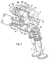
- the roller 17b is arranged on the side of the rocker arm 17c. This asymmetrical design, which can be seen particularly clearly from FIG. 9, results in an extremely space-saving design.
- the roller 17b is also mounted on one Axle that is attached on the one hand to the rocker arm 17c and on the other hand to a further secondary arm 17e. This secondary arm 17e also leads from the rocker arm bearing 17a to the receptacle 17d.
Abstract
Eine Brennkraftmaschine besitzt je Zylinder zumindest zwei Einlaß-Hubventile (4, 4'), deren Hubverlauf voneinander verschiedenartig verstellbar ist. Die Verstellung erfolgt mittels einer Exzenterwelle (10), die den Abstützpunkt eines zwischen jedem Nocken (5a, 5a') und jedem Hubventil (4, 4') liegenden Übertragungsgliedes (19, 19') verschiebt, wobei die beiden einem Zylinder zugeordneten Exzenter (10a, 10a') von unterschiedlicher Geometrie sind. Das Übertragungsglied (19, 19') wird von einem sich auf dem Exzenter (10a, 10a') abstützenden sowie vom Nocken (5a, 5a') betätigten Schlepphebel (16, 16') gebildet, der seinerseits auf einen Schwinghebel (17, 17') einwirkt. Die jeweiligen Kontaktflächen werden durch Rollen gebildet. Beschrieben ist ferner ein weiteres Übertragungsglied, das eine Kulissenbahn aufweist. <IMAGE>An internal combustion engine has at least two inlet lift valves (4, 4 ') per cylinder, the stroke course of which can be adjusted differently from one another. The adjustment is carried out by means of an eccentric shaft (10) which shifts the support point of a transmission member (19, 19 ') located between each cam (5a, 5a') and each lift valve (4, 4 '), the two eccentrics assigned to a cylinder ( 10a, 10a ') are of different geometry. The transmission member (19, 19 ') is formed by a rocker arm (16, 16') which is supported on the eccentric (10a, 10a ') and is actuated by the cam (5a, 5a') and which is in turn connected to a rocker arm (17, 17 ') acts. The respective contact areas are formed by rollers. Another transmission element is described, which has a slide track. <IMAGE>
Description
Die Erfindung betrifft einen Ventiltrieb einer Brennkraftmaschine mit zumindest zwei parallel wirkenden, jeweils durch einen Nocken sowie ein Übertragungsglied betätigten Hubventilen je Zylinder, deren Ventilhubverlauf voneinander verschiedenartig verstellbar ist.The invention relates to a valve train of an internal combustion engine with at least two parallel-acting lift valves per cylinder, each actuated by a cam and a transmission element, the valve lift course of which can be adjusted differently from one another.
Ein derartiger Ventiltrieb ist beispielsweise aus der DE 37 39 246 A1 bekannt. Das Übetragungsglied ist dabei als Kipphebel ausgebildet, wobei einzelne Kipphebel der einem einzigen Zylinder zugeordneten Hubventile über Kupplungselemente miteinander verbunden werden können. Indem bei diesem bekannten Stand der Technik den einzelnen Kipphebeln unterschiedliche Nocken zugeordnet sind, ist es durch entsprechende Ansteuerung dieser Kipphebel-Kupplungen somit möglich, ein bestimmtes Hubventil entweder direkt durch den ihm zugeordneten Nocken oder durch den Nocken eines anderen Hubventiles zu betätigen. Der Ventilhubverlauf dieses bestimmten Hubventiles ist somit verschiedenartig von dem eines anderen Hubventiles veränderbar.Such a valve train is known for example from DE 37 39 246 A1. The transmission member is designed as a rocker arm, wherein individual rocker arms of the lift valves assigned to a single cylinder can be connected to one another via coupling elements. Since different cams are assigned to the individual rocker arms in this known prior art, it is thus possible, by appropriate control of these rocker arm clutches, to actuate a specific lift valve either directly by the cam assigned to it or by the cam of another lift valve. The course of the valve stroke of this particular lift valve can thus be varied in different ways from that of another lift valve.
Dieser bekannte Ventiltrieb ist insofern nachteilig, als an den einzelnen Hubventilen lediglich Hubverläufe erzeugt werden können, die durch die tatsächlich vorhandenen Nocken vorgegeben sind. Weitere Variationen sind dabei nicht möglich. Ferner erfahren die Kupplungselemente der Kipphebel bzw. Übertragungsglieder extrem hohe mechanische Belastungen.This known valve train is disadvantageous in that only stroke courses can be generated on the individual lift valves, which are caused by the actually existing ones Cams are specified. No further variations are possible. Furthermore, the coupling elements of the rocker arms or transmission members experience extremely high mechanical loads.
Aufgabe der Erfindung ist es daher, an einem Ventiltrieb mit zumindest zwei parallel wirkenden Hubventilen je Zylinder Maßnahmen aufzuzeigen, mit Hilfe derer der Ventilhubverlauf in vielfältiger Weise und verschiedenartig voneinander verstellt werden kann.It is therefore the object of the invention to demonstrate measures on a valve train with at least two parallel-acting lift valves per cylinder, with the aid of which the valve lift course can be adjusted in many different ways from one another.
Zur Lösung dieser Aufgabe ist vorgesehen, daß die Abstützpunkte der Übertragungsglieder über verdrehbare, auf einer gemeinsamen Exzenterwelle liegende Exzenter verstellbar sind, wobei sich die Erhebungskurven der zumindest zwei Exzenter je Zylinder voneinander unterscheiden. Vorteilhafte Weiterbildungen der Erfindung sind Inhalt der Unteransprüche.To achieve this object, it is provided that the support points of the transmission members are adjustable via rotatable eccentrics located on a common eccentric shaft, the elevation curves of the at least two eccentrics per cylinder differing from one another. Advantageous developments of the invention are the content of the subclaims.
Erfindungsgemäß sind die Abstützpunkte der zwischen die einzelnen Nocken sowie die einzelnen Ventile zwischengeschalteten Übertragungsglieder verstellbar. Bei diesen Übertragungsgliedern kann es sich wie im oben genannten Stand der Technik um einen Kipphebel oder auch um einen Schlepp- oder Schwinghebel handeln, daneben sind aber auch andere Ausführungsformen möglich, so beispielsweise ein eine Kulissenbahn für eine Walze aufweisendes Kulissenelement. Wird nun der Abstützpunkt dieses Schwing- oder Kipphebels oder des Kulissenelementes verschoben, so ergibt sich für das jeweilig zugeordnete Hubventil ein abgewandelter Hubverlauf, da der Nockenhub in verschiedenartiger Weise übertragen wird. Dieses Prinzip zur Variation des Ventilhubverlaufes ist zwar an sich bekannt (DE 38 33 540 C2), jedoch gibt diese bekannte Ausführungsform nicht an, wie der Abstützpunkt des Übertragungsgliedes auf einfache Weise verschoben werden kann.According to the invention, the support points of the transmission elements interposed between the individual cams and the individual valves are adjustable. As in the prior art mentioned above, these transmission links can be a rocker arm or also a rocker arm or rocker arm, but other embodiments are also possible, for example a link element having a link track for a roller. If the support point of this rocker arm or rocker arm or of the link element is now shifted, a modified stroke curve results for the respectively associated lift valve, since the cam stroke is transmitted in different ways. This principle for varying the valve stroke course is known per se (DE 38 33 540 C2), but this known embodiment does not specify how the support point of the transmission element can be shifted in a simple manner.
Erfindungsgemäß erfolgt dies mit Hilfe von Exzentern, an denen sich die Übertragungsglieder abstützen. Diese Exzenter sind Bestandteil einer gemeinsamen Exzenterwelle - sind mehrere Zylinder in Reihe angeordnet, so kann sich diese Exzenterwelle über sämtliche Zylinder erstrecken -, die in einfacher Weise verdreht werden kann. Erfindungsgemäß unterscheiden sich darüberhinaus die einem einzelnen Zylinder zugeordneten Exzenter. Dadurch ist es wie gewünscht möglich, die wiederum diesen einzelnen Exzentern zugeordneten Ventile verschiedenartig voneinander zu betätigen, bzw. deren Hubverlauf verschiedenartig voneinander zu verstellen.According to the invention, this is done with the aid of eccentrics on which the transmission members are supported. These eccentrics are part of a common eccentric shaft - if several cylinders are arranged in series, this eccentric shaft can extend over all cylinders - which can be rotated in a simple manner. According to the invention, the eccentrics assigned to an individual cylinder also differ. As a result, it is possible, as desired, to actuate the valves assigned to these individual eccentrics in different ways from one another, or to adjust their stroke course in different ways from one another.
Im folgenden wird die Erfindung anhand zweier bevorzugter Ausführungsbeispiele näher erläutert. Es zeigt:
Figur 1- Einen Halb-Querschnitt durch einen Brennkraftmaschinen-Zylinderkopf mit einem erfindungsgemäßen Ventiltrieb, wobei der maximale Nockenhub in einen maximalen Ventilhub umgesetzt ist,
Figur 2- die gleiche Anordnung, wobei der maximale Nockenhub lediglich minimalen Ventilhub bewirkt,
Figur 3- eine Teilansicht X aus
Figur 1 sowie Figur 4- in einem Diagramm mehrere mögliche Ventilhubverläufe.
Figur 5- einen Querschnitt durch einen Brennkraftmaschinen-Zylinderkopf mit einem weiteren erfindungsgemäßen Ventiltrieb,
Figur 6- eine perspektivische Ansicht des Ventiltriebes aus Fig. 5 für einen einzigen Zylinder,
Figur 7- die Ansicht aus Fig. 6 in einer anderen Perspektive,
Figur 8- eine Perspektivdarstellung insbesondere des Übertragungsgliedes dieses weiteren Ventiltriebes, sowie
Figur 9- eine Perspektivdarstellung des Schwinghebels, der Bestandteil des Übertragungsgliedes von Fig. 8 ist.
- Figure 1
- A half cross section through an internal combustion engine cylinder head with a valve train according to the invention, the maximum cam stroke being converted into a maximum valve stroke,
- Figure 2
- the same arrangement, with the maximum cam lift causing only minimal valve lift,
- Figure 3
- a partial view X of Figure 1 and
- Figure 4
- several possible valve lift profiles in one diagram.
- Figure 5
- 3 shows a cross section through an internal combustion engine cylinder head with a further valve train according to the invention,
- Figure 6
- 5 shows a perspective view of the valve drive from FIG. 5 for a single cylinder,
- Figure 7
- 6 from another perspective,
- Figure 8
- a perspective view in particular of the transmission member of this further valve train, and
- Figure 9
- a perspective view of the rocker arm, which is part of the transmission member of FIG. 8.
Mit der Bezugsziffer 1 ist ein Zylinderkopf einer Brennkraftmaschine bezeichnet. Dieser Zylinderkopf erstreckt sich in der Darstellung gemäß Figur 1 senkrecht zur Zeichenebene über mehrere Zylinder. Je Zylinder sind zumindest zwei Einlaßkanäle 2 zu einem Brennraum 3 vorhanden, wobei je Einlaßkanal 2 in bekannter Weise ein Hubventil 4 vorgesehen ist. Betätigt wird dieses Hubventil durch einen Nocken 5a einer Nockenwelle 5, wobei der Nocken 5a auf eine Walze 6 einwirkt, die ihrerseits auf dem Stößel 7 des Hubventiles 4 abrollt.The
Wie auch Figur 3 zeigt, ist die Walze 6 stufenförmig ausgebildet und besitzt mehrere Abrollstufen 6a, 6b, 6c. Mit der Abrollstufe 6a liegt die Walze 6 auf dem Stößel 7 auf, während die Abrollstufe 6b mit dem Nocken 5a Kontakt hat. Mit der Abrollstufe 6c schließlich wälzt die Walze 6 auf einer Kulissenbahn 8a eines Kulissenelementes 8 ab, so daß die Walze 6 insgesamt durch dieses Kulissenelement 8 entsprechend der Kulissenbahn 8a geführt ist. Insgesamt bildet somit das Kulissenelement 8 sowie die Walze 6 das sogenannte zwischen dem Nocken 5a sowie dem Hubventil 4 liegende Übertragungsglied 9.As FIG. 3 also shows, the
Wie ersichtlich stützt sich dieses Übertragungsglied 9 bzw. das Kulissenelement 8 an einem Exzenter 10a ab, der aus einer Exzenterwelle 10 herausgearbeitet ist. Wird nun die Exzenterwelle 10 um ihre Längsachse 10b verdreht - zwei verschiedene Positionen sind in den Figuren 1, 2 dargestellt -, so wird der Abstützpunkt des Kulissenelementes 8 bzw. des Übertragungsgliedes 9 verschoben. Hierdurch verändert sich auch die Lage der Walze 6 bzw. der Kulissenbahn 8a, die letztlich die durch den rotierenden Nocken 5a bewegte Walze 6 führt. Mit Veränderung des Abstützpunktes des Übertragungsgliedes 9 ergeben sich aber - wie ersichtlich - bei gleichem Nockenhub verschiedenen Ventilhübe. In Figur 1 ist der maximal erreichbare Ventilhub h bei maximalen Nockenhub gezeigt. Bei Figur 2 wird demgegenüber die Exzenterwelle 10 um ihre Längsachse 10b um 180° gedreht. Aus der daraus resultierenden Verschiebung des Übertragungsgliedes 9 ergibt sich bei maximalen Nockenhub ein Ventilhub nahezu vom Betrag 0, d.h. das Hubventil 4 wird lediglich minimal geöffnet.As can be seen, this
Zur Sicherstellung der beschriebenen Funktion ist ein Rückstellhebel 11 erforderlich, der ebenfalls an der Abrollstufe 6a der Walze 6 angreift und diese Walze somit stets gegen den Nocken 5a preßt. Dieser Rückstellhebel 11 wird in entsprechender Weise von einer Druckfeder 12a beaufschlagt. Hierzu ist die Druckfeder 12a zwischen einem auf den Rückstellhebel 11 einwirkenden Druckelement 12b sowie einem in den Zylinderkopf 1 eingeschraubten Führungselement 12c eingespannt. Lediglich prinzipiell dargestellt ist ferner die Längsführung 13 für das Kulissenelement 8.To ensure the function described, a
Wie Figur 3 zeigt, sind für jeden einzelnen Zylinder 14a, 14b des Brennkraftmaschinen-Zylinderkopfes 1 zwei Hubventile 4, 4' vorgesehen. Jedem Hubventil 4, 4' eines einzelnen Zylinders 14a bzw. 14b ist ein eigener Nocken 5a, 5a' sowie ein eigenes Übertragungsglied 9, 9' in Form eines eigenen Kulissenelementes 8, 8' sowie einer eigenen Walze 6, 6' zugeordnet. Dabei stützt sich jedes Kulissenelement 8, 8' an einem eigenen Exzenter 10a, 10a' der sich über den gesamten Zylinderkopf 1 erstreckenden Exzenterwelle 10 ab. Wie die Figuren 1, 2 zeigen, unterscheiden sich die beiden einem Zylinder 14a bzw. 14b zugeordneten Exzenter 10a, 10a' in ihrer Geometrie. Identisch sind die beiden Exzenter 10a, 10a' eines Zylinders lediglich in den Punkten des minimalen sowie des maximalen Exzenterhubes. Befindet sich somit die Exzenterwelle 10 in der in Figur 2 gezeigten Position, so bleiben trotz maximalen Nockenhubes die beiden Hubventile 4, 4' eines Zylinders nahezu geschlossen. Befindet sich hingegen die Exzenterwelle 10 in der Position gemäß Figur 1, so werden bei maximalem Nockenhub die beiden Hubventile 4, 4' maximal geöffnet (Ventilhub h). In Zwischenpositionen der Exzenterwelle hingegen werden die beiden Hubventile 4, 4' bei maximalem Nockenhub unterschiedlich weit geöffnet. Der Ventilhubverlauf dieser beiden Hubventile 4, 4' je Zylinder 14a bzw. 14b ist somit durch Verstellen der Exzenterwelle 10 voneinander verschiedenartig veränderbar.As FIG. 3 shows, two
Ersichtlich wird dies auch aus Figur 4, die in einer Diagrammdarstellung verschiedene Ventilhubverläufe zeigt. Auf der Abszisse ist der Kurbelwinkel bzw. Nockenwellen-Winkel aufgetragen, die Ordinate gibt den erreichbaren Ventilhub an. Dabei ist für jeden der einzelnen exemplarisch herausgegriffenen fünf Ventilhubverläufe die zugehörige Position der Exzenterwelle 10 angegeben. Der am ansteigenden Ast angegebene Zahlenwert bezieht sich dabei auf das erste Hubventil 4, während der am abfallenden Ast angegebene Zahlenwert die erforderliche Exzenterwellenposition für das zweite Hubventil 4' angibt. Die Position der Exzenterwelle 10 ist dabei durch Winkelgrade beschrieben, wobei die Position gemäß Figur 2 0° entspricht und die Position gemäß Figur 1 den Wert von 180° darstellt.This can also be seen from FIG. 4, which shows various valve lift profiles in a diagram. The crank angle or camshaft angle is plotted on the abscissa, the ordinate indicates the valve lift that can be achieved. The associated position of the
Man erkennt somit, daß wie bereits erläutert bei der Exzenterwellenposition 0° die beiden Hubventile 4, 4' lediglich einen äußerst geringen Ventilhub ausführen, während bei der Exzenterwellenposition 180° beide Hubventile 4, 4' ihren maximalen Ventilhub h erreichen. Den minimal möglichen Ventilhub behält das Hubventil 4' aber auch bei einer Exzenterwellenposition von 45° und 90° bei, während bei diesen Positionen das Hubventil 4 bereits deutliche Hübe ausführt.It can thus be seen that, as already explained, with the
Verschiedenartige Ventilhubverläufe zweier parallel wirkender Hubventile je Zylinder sind erwünscht, um die Ladungswechseldynamik sowie die Verwirbelung der in den Brennraum 3 eingebrachten Ladung zu verbessern. Mit der gezeigten sowie mit der im folgenden beschriebenen weiteren Konstruktion ist eine derartige Ventilhubcharakteristik für zumindest zwei parallel wirkende Hubventile je Zylinder auf einfache Weise erzielbar.Different valve stroke profiles of two parallel-acting lift valves per cylinder are desired in order to improve the dynamics of the gas exchange and the swirling of the charge introduced into the
Im zweiten Ausführungsbeispiel gemäß Fig. 5 ist mit der Bezugsziffer 1 wieder ein Zylinderkopf einer Brennkraftmaschine bezeichnet. Auch dieser Zylinderkopf erstreckt sich in der Darstellung senkrecht zur Zeichenebene über mehrere Zylinder. Je Zylinder sind zumindest zwei Einlaßkanäle 2 zum Brennraum 3 vorhanden, wobei je Einlaßkanal 2 ein Hubventil 4 vorgesehen ist. Betätigt wird jedes Hubventil 4, 4' durch jeweils einen Nocken 5a, 5a' einer Nockenwelle, wobei jeder Nocken auf einen Schlepphebel 16, 16' einwirkt, der seinerseits auf einen Schwinghebel 17, 17' wirkt. Im Schwinghebel 17, 17' ist ein hydraulisches Spielausgleichselement 18, 18' gelagert, auf dem sich letztendlich der Schaft des Hubventiles 4, 4' abstützt. Insgesamt bildet der Schlepphebel 16 sowie der Schwinghebel 17 ein Übertragungsglied 19 bzw. 19', mittels dessen der Hubverlauf des Nockens 5a bzw. 5a' auf das Hubventil 4 bzw. 4' übertragen wird.In the second exemplary embodiment according to FIG. 5, the
Wie ersichtlich stützt sich das Übertragungsglied 19 bzw. der Schlepphebel 16 an einem Exzenter 10a ab, der aus einer Exzenterwelle 10 herausgearbeitet ist. Wird die Exzenterwelle 10 um ihre Längsachse 10b verdreht, so wird der Abstützpunkt des Schlepphebels 16 bzw. des Übertragungsgliedes 19 verschoben. Mit einer derartigen Veränderung des Abstützpunktes des Übertragungsgliedes 19 ergeben sich bei gleichem Nockenhub unterschiedliche Ventilhübe, da aufgrund der geänderten Abstützung der Schlepphebel 16 bei Rotation des Nockens 5a gegenüber dem Schwinghebel 17 eine unterschiedliche Bewegungsbahn durchläuft, so daß auch der Schwinghebel 17 unterschiedlich ausgelenkt wird. Insbesondere ist es hiermit möglich, neben einem maximalen Ventilhub auch einen Ventilhub nahezu vom Betrag 0 zu erzielen, bei dem das Hubventil 4 lediglich minimal geöffnet wird.As can be seen, the
Geführt wird der Schlepphebel 16 durch eine in ihrer Gesamtheit mit der Bezugsziffer 20 bezeichnete Bolzen-Lang-loch-Führung. Wie ersichtlich weist der Schlepphebel 16 ein Langloch 20a auf, über welches er in einen Bolzen 20b eingehängt ist, der am Zylinderkopf in einer Lagerstelle 20c befestigt ist. Aufgrund dieser Bolzen-Langloch-Führung 20 kann somit der Schlepphebel 16 unterschiedliche Positionen einnehmen. Selbstverständlich kann die Bolzen-Langloch-Führung 20 auch umgekehrt ausgebildet sein, d. h. der Bolzen 20b kann am Schlepphebel 16 befestigt sein und das Langloch 20a kann dann in der Zylinderkopf-Lagerstelle 20c vorgesehen sein. Zur Sicherstellung der beschriebenen Verstellfunktion greift ferner an einem Absatz 16a des Schlepphebels ein Rückstelldorn 11 an, der den Schlepphebel 16 stets sowohl gegen den Nocken 5a als auch gegen den Exzenter 10a preßt. Hierzu wird der Rückstelldorn 11 in entsprechender Weise von einer Druckfeder 12a beaufschlagt, die sich an einem in den Zylinderkopf 1 eingeschraubten Führungselement 12c abstützt.The
Wie die Fig. 6, 7 zeigen, sind für jeden Zylinder bzw. Brennraum 3 des Brennkraftmaschinen-Zylinderkopfes 1 zwei Hubventile 4, 4' vorgesehen. Jedem Hubventil 4, 4' ist ein eigener Nocken 5a, 5a' sowie ein eigenes Übertragungsglied 19, 19' in Form eines eigenen Schlepphebels 16, 16' sowie eines eigenen Schwinghebels 17, 17' zugeordnet. Dabei stützt sich jeder Schlepphebel 16, 16' an einem eigenen Exzenter 10a, 10a' der sich über den gesamten Zylinderkopf 1 erstreckenden Exzenterwelle 10 ab. Wie Fig. 5 zeigt, unterscheiden sich die beiden einem Zylinder bzw. Brennraum 3 zugeordneten Exzenter 10a, 10a' in ihrer Geometrie. Identisch sind die beiden Exzenter 10a, 10a' eines Zylinders/Brennraumes lediglich in den Punkten des minimalen sowie des maximalen Exzenterhubes. In der gezeigten Position minimalen Exzenterhubes bleiben die beiden Hubventile 4, 4' eines Zylinders trotz maximalen Nockenhubes nahezu geschlossen. Wird hingegen ausgehend von der gezeigten Position die Exzenterwelle 10 um 180° gedreht und verstellen somit die Exzenter 10a, 10a' aufgrund ihres dann maximalen Exzenterhubes die Schlepphebel 16, 16' dementsprechend, so werden bei maximalem Nockenhub die beiden Hubventile 4, 4' maximal geöffnet. In Zwischenpositionen der Exzenterwelle 10 hingegen werden die beiden Hubventile 4, 4' bei maximalem Nockenhub unterschiedlich weit geöffnet. Der Ventilhubverlauf dieser beiden Hubventile 4, 4' ist somit durch Verstellen der Exzenterwelle 10 voneinander verschiedenartig veränderbar.6, 7 show, two
Indem das Übertragungsglied 19 durch einen Schlepphebel 16 sowie durch einen nachgeschalteten Schwinghebel 17 gebildet wird, ergibt sich eine äußerst zuverlässige Konstruktion, die sich darüber hinaus durch eine raumsparende Bauweise auszeichnet. Um die Reibungsverluste im Ventiltrieb gering zu halten, ist in den Kontaktbereichen zwischen dem Nocken 5a und dem Schlepphebel 16 sowie zwischen dem Schlepphebel 16 und dem Schwinghebel 17 eine Rollreibung realisiert, d. h. der Schlepphebel 16 trägt eine Rolle 16b und der Schinghebel 17 trägt eine Rolle 17b.Because the
Die Rolle 16b jedes Schlepphebels 16 ist zwischen den beiden Armen 16c des abschnittsweise zweiarmig ausgebildeten Schlepphebels geführt und auf einer nicht näher bezeichneten, in diesen Schlepphebel-Armen befestigten Rollenachse gelagert. Aufgrund der Zweiarmigkeit des Schlepphebels 16 in dem insbesondere aus der Darstellung gemäß Fig. 4 hervorgehenden Abschnitt ist - insbesondere zur Gewichtsreduzierung - auch der diesem Schlepphebel 16 zugeordnete Exzenter 10a zweiteilig ausgebildet, d. h. für jeden der Schlepphebel-Arme 16c ist eine eigene Exzenterscheibe vorgesehen, wobei die beiden nebeneinanderliegenden, lediglich um die Breite der Rolle 16b voneinander beabstandeten Exzenterscheiben selbstverständlich von gleicher Konfiguration sind.The
Der Schwinghebel 17 weist - wie an sich bekannt - ein Schwinghebel-Lager 17a auf, von dem ausgehend ein Schwinghebelarm 17c zu einer Aufnahme 17d führt, die das auf das Hubventil 4 einwirkende hydraulische Spielausgleichselement 18 trägt. Seitlich am Schwinghebelarm 17c ist die Rolle 17b angeordnet. Mit dieser asymmetrischen Gestaltung, die besonders deutlich aus Fig. 9 hervorgeht, ergibt sich eine äußerst raumsparende Bauweise. Gelagert ist die Rolle 17b dabei ebenfalls auf einer Achse, die einerseits am Schwinghebelarm 17c und andererseits an einem weiteren Nebenarm 17e befestigt ist. Dieser Nebenarm 17e führt dabei ebenfalls vom Schwinghebellager 17a zur Aufnahme 17d.The
Die gleichen Vorteile hinsichtlich zuverlässiger, einfacher und raumsparender Bauweise, die sich aufgrund der Tatsache einstellen, daß das Übertragungsglied durch den Schlepphebel 16 sowie den Schwinghebel 17 gebildet wird, stellen sich selbstverständlich auch dann ein, wenn die Kontaktflächen sowohl zwischen dem Nocken 5a sowie dem Übertragungsglied 19 als auch innerhalb desselben nicht durch die Rollen 16b, 17b gebildet werden, sondern wenn diese Kontaktflächen als ballige oder gerade Gleitflächen ausgebildet sind. Dabei zeichnen sich die beiden beschriebenen Systeme nicht nur durch einfache konstruktive Gestaltung, sondern auch durch höchste Zuverlässigkeit aus. Selbstverständlich sind darüber hinaus eine Vielzahl weiterer Abweichungen insbesondere konstruktiver Art von den gezeigten Ausführungsbeispielen möglich, ohne den Inhalt der Patentansprüche zu verlassen.The same advantages in terms of reliable, simple and space-saving design, which arise due to the fact that the transmission member is formed by the
Claims (7)
dadurch gekennzeichnet, daß die Abstützpunkte der Übertragungsglieder (9, 9', 19, 19') über verdrehbare, auf einer gemeinsamen Exzenterwelle (10) liegende Exzenter (10a, 10a') verstellbar sind, wobei sich die Erhebungskurven der zumindest zwei Exzenter (10a, 10a') je Zylinder (14a, 14b) voneinander unterscheiden.Valve train of an internal combustion engine with at least two parallel-acting lift valves (4, 4 ') per cylinder (14a, 14b), each operated by a cam (5a, 5a') and a transmission element (9, 9 ', 19, 19') is differently adjustable from one another,
characterized in that the support points of the transmission members (9, 9 ', 19, 19') can be adjusted via rotatable eccentrics (10a, 10a ') located on a common eccentric shaft (10), the elevation curves of the at least two eccentrics (10a , 10a ') from each cylinder (14a, 14b).
gekennzeichnet durch eine gemeinsame Exzenterwelle (10) für die in Reihe angeordneten Zylinder (14a, 14b).Valve train of a multi-cylinder internal combustion engine according to claim 1,
characterized by a common eccentric shaft (10) for the cylinders (14a, 14b) arranged in series.
dadurch gekennzeichnet, daß das Übertragungsglied (9) als eine zwischen dem Stößel (7) des Hubventiles (4) sowie dem Nocken (5a) abwälzende Walze (6) ausgebildet ist, die weiterhin durch ein mittels des Exzenters (10a) verstellbares Kulissenelement (8) geführt ist.Valve train according to claim 1 or 2,
characterized in that the transmission member (9) as a roller (6) which rolls between the tappet (7) of the lift valve (4) and the cam (5a) is formed, which is further guided by a link element (8) adjustable by means of the eccentric (10a).
dadurch gekennzeichnet, daß die Walze (6) verschiedene mit dem Nocken (5a) oder mit dem Stößel (7) oder mit der Kulissenbahn (8a) des Kulissenelementes (8) zusammenwirkende Abrollstufen (6a, 6b, 6c) aufweist.Valve train according to claim 3,
characterized in that the roller (6) has various rolling stages (6a, 6b, 6c) which interact with the cam (5a) or with the tappet (7) or with the slide track (8a) of the slide element (8).
dadurch gekennzeichnet, daß an der Walze (6) ein Rückstellhebel (11) angreift.Valve train according to claim 3 or 4,
characterized in that a return lever (11) acts on the roller (6).
dadurch gekennzeichnet, daß das Übertragungsglied (19, 19') als ein sich am Exzenter (10a, 10a') abstützender Schlepphebel (16, 16'), der auf einen Schwinghebel (17, 17') einwirkt, ausgebildet ist.Valve train according to claim 1 or 2
characterized in that the transmission member (19, 19 ') is designed as a rocker arm (16, 16') which is supported on the eccentric (10a, 10a ') and acts on a rocker arm (17, 17').
gekennzeichnet durch zumindest eines der folgenden Merkmale:
characterized by at least one of the following features:
Applications Claiming Priority (2)
| Application Number | Priority Date | Filing Date | Title |
|---|---|---|---|
| DE4326331 | 1993-08-05 | ||
| DE19934326331 DE4326331A1 (en) | 1992-07-15 | 1993-08-05 | Valve gear of an internal combustion engine |
Publications (1)
| Publication Number | Publication Date |
|---|---|
| EP0638706A1 true EP0638706A1 (en) | 1995-02-15 |
Family
ID=6494543
Family Applications (1)
| Application Number | Title | Priority Date | Filing Date |
|---|---|---|---|
| EP93119520A Withdrawn EP0638706A1 (en) | 1993-08-05 | 1993-12-03 | Valve actuating mechanism of an internal combustion engine |
Country Status (3)
| Country | Link |
|---|---|
| US (1) | US5373818A (en) |
| EP (1) | EP0638706A1 (en) |
| JP (1) | JP3245492B2 (en) |
Cited By (17)
| Publication number | Priority date | Publication date | Assignee | Title |
|---|---|---|---|---|
| EP0780547A1 (en) | 1995-12-22 | 1997-06-25 | Siemens Aktiengesellschaft | Internal combustion engine valve lift varying device |
| WO1998003778A1 (en) | 1996-07-20 | 1998-01-29 | Dieter Reitz | Valve drive system and cylinder head for an internal combustion engine |
| WO1999009303A1 (en) | 1997-08-14 | 1999-02-25 | Siemens Aktiengesellschaft | Method for adjusting a valve lift |
| DE19810369C1 (en) * | 1998-03-10 | 1999-08-12 | Siemens Ag | Appts. to measure valve lift in petrol-driven internal combustion (IC) engine |
| DE19920512A1 (en) * | 1999-05-05 | 2000-11-09 | Opel Adam Ag | Device for actuating a valve with a variable stroke on internal combustion engines |
| US6164254A (en) * | 1997-08-14 | 2000-12-26 | Siemens Aktiengesellschaft | Method for setting valve lift |
| DE19942934A1 (en) * | 1999-09-08 | 2001-03-15 | Siemens Ag | Maximum valve-lift measurement method e.g. for a petrol powered combustion engine gas-exchange valve |
| EP1143118A3 (en) * | 2000-04-07 | 2002-11-13 | Bayerische Motoren Werke Aktiengesellschaft | Device for varying the valve lift in an engine cylinder head |
| WO2004057160A1 (en) * | 2002-12-21 | 2004-07-08 | Ina-Schaeffler Kg | Intermediate lever for a variable valve drive of an internal combustion engine |
| EP1666714A2 (en) * | 2004-10-14 | 2006-06-07 | Bayerische Motoren Werke Aktiengesellschaft | Combustion engine block |
| DE10251007B4 (en) * | 2001-11-15 | 2007-09-06 | Avl List Gmbh | Internal combustion engine operated with spark ignitable fuel |
| DE102006018512A1 (en) * | 2006-04-21 | 2007-10-25 | Schaeffler Kg | Roller element for a pivotable machine part |
| DE102010048709A1 (en) | 2010-10-19 | 2012-04-19 | Kolbenschmidt Pierburg Innovations Gmbh | Mechanically controllable valve drive and mechanically controllable valve train arrangement |
| WO2012126648A1 (en) | 2011-03-22 | 2012-09-27 | Kolbenschmidt Pierburg Innovations Gmbh | Mechanically controllable valve drive and mechanically controllable valve drive arrangement |
| DE102013113815A1 (en) | 2013-12-11 | 2015-06-11 | Pierburg Gmbh | Transmission arrangement for a mechanically controllable valve train |
| DE102014114396A1 (en) | 2014-10-02 | 2016-04-07 | Pierburg Gmbh | Mechanically controllable valve drive and mechanically controllable valve train arrangement |
| EP3073072A2 (en) | 2015-03-26 | 2016-09-28 | Pierburg GmbH | Mechanically controllable valve drive and mechanically controllable valve drive assembly |
Families Citing this family (82)
| Publication number | Priority date | Publication date | Assignee | Title |
|---|---|---|---|---|
| DE19509604A1 (en) * | 1995-03-16 | 1996-09-19 | Bayerische Motoren Werke Ag | Valve train of an internal combustion engine |
| IT1285853B1 (en) * | 1996-04-24 | 1998-06-24 | Fiat Ricerche | INTERNAL COMBUSTION ENGINE WITH VARIABLE OPERATION VALVES. |
| WO2000068565A1 (en) * | 1999-05-10 | 2000-11-16 | Armer & Frank Motors, Llc | Valve system having improved opening and breathing characteristics for internal combustion engines |
| JP2001164911A (en) * | 1999-12-10 | 2001-06-19 | Yamaha Motor Co Ltd | Valve system of four-cycle engine |
| DE10016103A1 (en) | 2000-03-31 | 2001-10-04 | Audi Ag | Variable valve timing |
| DE10052811A1 (en) * | 2000-10-25 | 2002-05-08 | Ina Schaeffler Kg | Variable valve train for load control of a spark ignition internal combustion engine |
| GB2389628B (en) * | 2001-04-05 | 2005-08-17 | Stephen William Mitchell | Variable valve timing system |
| GR20010100295A (en) | 2001-06-18 | 2003-02-27 | Εμμανουηλ Παττακος | Variable valve gear |
| DE10136612A1 (en) * | 2001-07-17 | 2003-02-06 | Herbert Naumann | Variable lift valve controls |
| DE10206465A1 (en) * | 2002-02-16 | 2003-08-28 | Mahle Ventiltrieb Gmbh | Control unit for a gas exchange valve in a combustion engine with a multi-component drive, has curved part with separate sectional effects |
| DE10211999A1 (en) * | 2002-03-18 | 2003-10-02 | Ina Schaeffler Kg | Method and device for controlling the cylinder charge of a spark-ignition internal combustion engine |
| JP4276620B2 (en) * | 2002-05-17 | 2009-06-10 | ヤマハ発動機株式会社 | Engine valve gear |
| WO2003098013A1 (en) | 2002-05-17 | 2003-11-27 | Yamaha Hatsudoki Kabushiki Kaisha | Engine valve driver |
| US6659053B1 (en) | 2002-06-07 | 2003-12-09 | Eaton Corporation | Fully variable valve train |
| DE10228022B4 (en) * | 2002-06-20 | 2009-04-23 | Entec Consulting Gmbh | Valve lifting device for stroke adjustment of the gas exchange valves of an internal combustion engine |
| DE10261304B4 (en) * | 2002-12-27 | 2009-01-22 | BÖSL-FLIERL, Gerlinde | Valve lift device for variable valve control of the gas exchange valves of an internal combustion engine |
| US7107949B2 (en) * | 2003-02-19 | 2006-09-19 | Iav Gmbh Ingenieurgesellschaft Auto Und Verkeh | Device for variable activation of valves for internal combustion engines |
| EP1605142B1 (en) | 2003-03-11 | 2014-01-01 | Yamaha Hatsudoki Kabushiki Kaisha | Variable valve mechanism for internal combustion engine |
| US7007649B2 (en) * | 2003-03-18 | 2006-03-07 | General Motors Corporation | Engine valve actuator assembly |
| US6688267B1 (en) | 2003-03-19 | 2004-02-10 | General Motors Corporation | Engine valve actuator assembly |
| DE10314683B4 (en) | 2003-03-29 | 2009-05-07 | Entec Consulting Gmbh | Variable valve lift control for a combustion engine with a bottom camshaft |
| JP4669471B2 (en) * | 2003-03-29 | 2011-04-13 | ヒュドラオリク−リング・ゲーエムベーハー | Variable valve lift device for lift adjustment of gas exchange valve of internal combustion engine |
| US6883474B2 (en) * | 2003-04-02 | 2005-04-26 | General Motors Corporation | Electrohydraulic engine valve actuator assembly |
| US6886510B2 (en) | 2003-04-02 | 2005-05-03 | General Motors Corporation | Engine valve actuator assembly with dual hydraulic feedback |
| US6918360B2 (en) * | 2003-04-02 | 2005-07-19 | General Motors Corporation | Engine valve actuator assembly with hydraulic feedback |
| US6837196B2 (en) * | 2003-04-02 | 2005-01-04 | General Motors Corporation | Engine valve actuator assembly with automatic regulation |
| JP4248344B2 (en) * | 2003-05-01 | 2009-04-02 | ヤマハ発動機株式会社 | Engine valve gear |
| JP4248343B2 (en) | 2003-05-01 | 2009-04-02 | ヤマハ発動機株式会社 | Engine valve gear |
| JP2007502934A (en) * | 2003-08-18 | 2007-02-15 | マノウソス パタコス | Variable valve device |
| JP4247529B2 (en) * | 2003-08-22 | 2009-04-02 | ヤマハ発動機株式会社 | Valve mechanism of internal combustion engine |
| JP4237643B2 (en) | 2003-08-25 | 2009-03-11 | ヤマハ発動機株式会社 | Valve mechanism of internal combustion engine |
| JP2005069014A (en) * | 2003-08-25 | 2005-03-17 | Yamaha Motor Co Ltd | Valve system of internal combustion engine |
| JP4039383B2 (en) * | 2003-10-21 | 2008-01-30 | トヨタ自動車株式会社 | Internal combustion engine using hydrogen |
| US6945204B2 (en) * | 2003-11-12 | 2005-09-20 | General Motors Corporation | Engine valve actuator assembly |
| JP4225321B2 (en) | 2003-12-18 | 2009-02-18 | トヨタ自動車株式会社 | Variable valve mechanism |
| WO2005059321A1 (en) * | 2003-12-18 | 2005-06-30 | Toyota Jidosha Kabushiki Kaisha | Variable valve mechanism |
| JP4238203B2 (en) | 2004-01-30 | 2009-03-18 | 本田技研工業株式会社 | engine |
| JP4381188B2 (en) * | 2004-03-19 | 2009-12-09 | 三菱ふそうトラック・バス株式会社 | Variable valve operating device for internal combustion engine |
| WO2005090758A1 (en) | 2004-03-23 | 2005-09-29 | Mitsubishi Fuso Truck And Bus Corporation | Variable valve gear of internal combustion engine |
| US6994063B2 (en) | 2004-04-13 | 2006-02-07 | Mitsubishi Fuso Truck And Bus Corporation | Variable valve unit for internal combustion engine |
| JP4327645B2 (en) * | 2004-04-13 | 2009-09-09 | 三菱ふそうトラック・バス株式会社 | Variable valve operating device for V-type engine |
| JP4221327B2 (en) | 2004-04-13 | 2009-02-12 | 三菱ふそうトラック・バス株式会社 | Variable valve operating device for internal combustion engine |
| JP4412190B2 (en) | 2004-04-28 | 2010-02-10 | トヨタ自動車株式会社 | Variable valve mechanism |
| JP4342372B2 (en) | 2004-04-28 | 2009-10-14 | 本田技研工業株式会社 | Valve operating device for internal combustion engine |
| JP4343021B2 (en) | 2004-04-28 | 2009-10-14 | 本田技研工業株式会社 | Valve operating device for internal combustion engine |
| JP4103872B2 (en) | 2004-08-31 | 2008-06-18 | トヨタ自動車株式会社 | Variable valve gear |
| JP4103871B2 (en) | 2004-08-31 | 2008-06-18 | トヨタ自動車株式会社 | Variable valve gear |
| JP4278590B2 (en) | 2004-08-31 | 2009-06-17 | 株式会社日立製作所 | Variable valve operating device for internal combustion engine |
| JP4026634B2 (en) | 2004-08-31 | 2007-12-26 | トヨタ自動車株式会社 | Variable valve gear |
| US7299775B2 (en) | 2004-08-31 | 2007-11-27 | Toyota Jidosha Kabushiki Kaisha | Variable valve operating device |
| US6932035B1 (en) * | 2005-01-28 | 2005-08-23 | Ford Global Technologies, Llc | Cylinder valve operating system for internal combustion engine |
| JP2006307765A (en) | 2005-04-28 | 2006-11-09 | Honda Motor Co Ltd | Lift variable valve mechanism of internal combustion engine |
| JP2006329084A (en) | 2005-05-26 | 2006-12-07 | Yamaha Motor Co Ltd | Valve gear of engine |
| JP2006329164A (en) | 2005-05-30 | 2006-12-07 | Yamaha Motor Co Ltd | Multi-cylinder engine |
| JP4507997B2 (en) * | 2005-06-15 | 2010-07-21 | 三菱自動車工業株式会社 | Variable valve operating device for internal combustion engine |
| JP4546427B2 (en) * | 2006-07-19 | 2010-09-15 | 本田技研工業株式会社 | Variable valve mechanism for internal combustion engine |
| DE102005040959A1 (en) * | 2005-08-30 | 2007-03-08 | Bayerische Motoren Werke Ag | Hubvariabler valve drive for an internal combustion engine |
| JP2007077940A (en) * | 2005-09-15 | 2007-03-29 | Otics Corp | Variable valve train |
| JP2007127117A (en) * | 2005-10-04 | 2007-05-24 | Masaaki Yoshikawa | Valve system apparatus for four-stroke internal combustion engine |
| JP4518010B2 (en) * | 2005-12-01 | 2010-08-04 | 三菱自動車工業株式会社 | Variable valve operating device for internal combustion engine |
| JP2007198363A (en) * | 2005-12-26 | 2007-08-09 | Otics Corp | Variable valve gear |
| US7162983B1 (en) | 2006-02-22 | 2007-01-16 | Gm Global Technology Operations, Inc. | Valve actuator assembly for variable displacement of an engine valve |
| JP4697011B2 (en) * | 2006-04-03 | 2011-06-08 | トヨタ自動車株式会社 | Variable valve mechanism |
| JP4519104B2 (en) * | 2006-06-01 | 2010-08-04 | 日立オートモティブシステムズ株式会社 | Variable valve operating device for internal combustion engine |
| JP4726775B2 (en) | 2006-12-20 | 2011-07-20 | ヤマハ発動機株式会社 | Continuously variable valve gear for engine |
| US7404386B1 (en) | 2007-02-13 | 2008-07-29 | Gm Global Technology Operations, Inc. | Multi-step valve actuation system |
| JP2009091943A (en) * | 2007-10-05 | 2009-04-30 | Honda Motor Co Ltd | Valve opening characteristic variable type internal combustion engine |
| JP4440293B2 (en) | 2007-10-05 | 2010-03-24 | 本田技研工業株式会社 | Variable valve opening characteristics internal combustion engine |
| JP5137595B2 (en) * | 2008-01-18 | 2013-02-06 | ダイハツ工業株式会社 | Variable valve lift system for internal combustion engine |
| KR100986355B1 (en) * | 2008-07-23 | 2010-10-08 | 현대자동차주식회사 | Slide type continuous variable valve lift device |
| EP2157292A1 (en) | 2008-08-20 | 2010-02-24 | Delphi Technologies, Inc. | Valve gear assembly for an internal combustion engine |
| US8602002B2 (en) | 2010-08-05 | 2013-12-10 | GM Global Technology Operations LLC | System and method for controlling engine knock using electro-hydraulic valve actuation |
| DE102010048708A1 (en) * | 2010-10-19 | 2012-04-19 | Kolbenschmidt Pierburg Innovations Gmbh | Mechanically controllable valve train |
| US8839750B2 (en) | 2010-10-22 | 2014-09-23 | GM Global Technology Operations LLC | System and method for controlling hydraulic pressure in electro-hydraulic valve actuation systems |
| US8781713B2 (en) | 2011-09-23 | 2014-07-15 | GM Global Technology Operations LLC | System and method for controlling a valve of a cylinder in an engine based on fuel delivery to the cylinder |
| US9169787B2 (en) | 2012-05-22 | 2015-10-27 | GM Global Technology Operations LLC | Valve control systems and methods for cylinder deactivation and activation transitions |
| US9567928B2 (en) | 2012-08-07 | 2017-02-14 | GM Global Technology Operations LLC | System and method for controlling a variable valve actuation system to reduce delay associated with reactivating a cylinder |
| CN103244230B (en) * | 2013-05-23 | 2015-07-01 | 长城汽车股份有限公司 | Vehicle, engine and variable valve lift device of vehicle |
| EP3296531A1 (en) * | 2016-09-14 | 2018-03-21 | Mechadyne International Limited | Engine valve system |
| CN108561231B (en) * | 2017-06-09 | 2020-09-04 | 长城汽车股份有限公司 | Control strategy for continuously variable valve lift mechanism |
| JP2020033872A (en) * | 2018-08-27 | 2020-03-05 | 株式会社オティックス | Variable valve mechanism of internal combustion engine |
| CN112282959A (en) * | 2020-10-28 | 2021-01-29 | 哈尔滨工程大学 | Four exhaust valve structures of marine low-speed machine of two-stroke |
Citations (7)
| Publication number | Priority date | Publication date | Assignee | Title |
|---|---|---|---|---|
| FR2506834A1 (en) * | 1981-05-27 | 1982-12-03 | Honda Motor Co Ltd | DEVICE FOR VARIABLE TIMING OF VALVE OF AN INTERNAL COMBUSTION ENGINE |
| WO1983002301A1 (en) * | 1981-12-31 | 1983-07-07 | BAGUÉNA, Michel | Variable timing for four stroke engine |
| DE3621080A1 (en) * | 1985-06-24 | 1987-01-02 | Nissan Motor | VALVE TIMING DEVICE FOR COMBUSTION ENGINES WITH SEVERAL INLET VALVES PER CYLINDER |
| DE3730001A1 (en) * | 1987-09-08 | 1989-03-30 | Gerhard Werner Kappelmeier | Valve actuating mechanism for an internal combustion engine |
| EP0319956A1 (en) * | 1987-12-08 | 1989-06-14 | Nissan Motor Co., Ltd. | Valve operating mechanism |
| EP0462853A1 (en) * | 1990-06-21 | 1991-12-27 | Automobiles Peugeot | Variable amplitude device for the lift of at least one internal combustion engine valve |
| US5189998A (en) * | 1991-07-23 | 1993-03-02 | Atsugi Unisia Corporation | Valve mechanism of internal combustion engine |
Family Cites Families (8)
| Publication number | Priority date | Publication date | Assignee | Title |
|---|---|---|---|---|
| US3413965A (en) * | 1967-07-13 | 1968-12-03 | Ford Motor Co | Mechanism for varying the operation of a reciprocating member |
| US4138973A (en) * | 1974-06-14 | 1979-02-13 | David Luria | Piston-type internal combustion engine |
| US4526142A (en) * | 1981-06-24 | 1985-07-02 | Nissan Motor Company, Limited | Variable valve timing arrangement for an internal combustion engine or the like |
| JPH036801Y2 (en) * | 1986-11-18 | 1991-02-20 | ||
| DE3833540A1 (en) * | 1988-10-01 | 1990-04-12 | Peter Prof Dr Ing Kuhn | DEVICE FOR ACTUATING THE VALVES OF INTERNAL COMBUSTION ENGINES WITH VARIABLE VALVE LIFTING CURVE |
| JP2700692B2 (en) * | 1989-06-30 | 1998-01-21 | スズキ株式会社 | Valve system for 4-cycle engine |
| US5111781A (en) * | 1990-03-14 | 1992-05-12 | Suzuki Kabushiki Kaisha | Valve actuating mechanism in four-stroke cycle engine |
| US5025761A (en) * | 1990-06-13 | 1991-06-25 | Chen Kuang Tong | Variable valve-timing device |
-
1993
- 1993-12-03 EP EP93119520A patent/EP0638706A1/en not_active Withdrawn
- 1993-12-24 JP JP32807293A patent/JP3245492B2/en not_active Expired - Fee Related
- 1993-12-30 US US08/176,280 patent/US5373818A/en not_active Expired - Lifetime
Patent Citations (7)
| Publication number | Priority date | Publication date | Assignee | Title |
|---|---|---|---|---|
| FR2506834A1 (en) * | 1981-05-27 | 1982-12-03 | Honda Motor Co Ltd | DEVICE FOR VARIABLE TIMING OF VALVE OF AN INTERNAL COMBUSTION ENGINE |
| WO1983002301A1 (en) * | 1981-12-31 | 1983-07-07 | BAGUÉNA, Michel | Variable timing for four stroke engine |
| DE3621080A1 (en) * | 1985-06-24 | 1987-01-02 | Nissan Motor | VALVE TIMING DEVICE FOR COMBUSTION ENGINES WITH SEVERAL INLET VALVES PER CYLINDER |
| DE3730001A1 (en) * | 1987-09-08 | 1989-03-30 | Gerhard Werner Kappelmeier | Valve actuating mechanism for an internal combustion engine |
| EP0319956A1 (en) * | 1987-12-08 | 1989-06-14 | Nissan Motor Co., Ltd. | Valve operating mechanism |
| EP0462853A1 (en) * | 1990-06-21 | 1991-12-27 | Automobiles Peugeot | Variable amplitude device for the lift of at least one internal combustion engine valve |
| US5189998A (en) * | 1991-07-23 | 1993-03-02 | Atsugi Unisia Corporation | Valve mechanism of internal combustion engine |
Cited By (30)
| Publication number | Priority date | Publication date | Assignee | Title |
|---|---|---|---|---|
| EP0780547A1 (en) | 1995-12-22 | 1997-06-25 | Siemens Aktiengesellschaft | Internal combustion engine valve lift varying device |
| DE19548389A1 (en) * | 1995-12-22 | 1997-06-26 | Siemens Ag | Adjustment device for the stroke of a gas exchange valve of an internal combustion engine |
| WO1998003778A1 (en) | 1996-07-20 | 1998-01-29 | Dieter Reitz | Valve drive system and cylinder head for an internal combustion engine |
| US6164254A (en) * | 1997-08-14 | 2000-12-26 | Siemens Aktiengesellschaft | Method for setting valve lift |
| WO1999009303A1 (en) | 1997-08-14 | 1999-02-25 | Siemens Aktiengesellschaft | Method for adjusting a valve lift |
| DE19810369C1 (en) * | 1998-03-10 | 1999-08-12 | Siemens Ag | Appts. to measure valve lift in petrol-driven internal combustion (IC) engine |
| DE19920512A1 (en) * | 1999-05-05 | 2000-11-09 | Opel Adam Ag | Device for actuating a valve with a variable stroke on internal combustion engines |
| DE19942934A1 (en) * | 1999-09-08 | 2001-03-15 | Siemens Ag | Maximum valve-lift measurement method e.g. for a petrol powered combustion engine gas-exchange valve |
| DE19942934B4 (en) * | 1999-09-08 | 2005-08-04 | Siemens Ag | Method for using the value of the maximum valve lift of a gas exchange valve |
| EP1143118A3 (en) * | 2000-04-07 | 2002-11-13 | Bayerische Motoren Werke Aktiengesellschaft | Device for varying the valve lift in an engine cylinder head |
| DE10251007B4 (en) * | 2001-11-15 | 2007-09-06 | Avl List Gmbh | Internal combustion engine operated with spark ignitable fuel |
| WO2004057160A1 (en) * | 2002-12-21 | 2004-07-08 | Ina-Schaeffler Kg | Intermediate lever for a variable valve drive of an internal combustion engine |
| US7055478B2 (en) | 2002-12-21 | 2006-06-06 | Ina-Schaeffler Kg | Intermediate lever for a variable valve train of an internal combustion engine |
| EP1666714A3 (en) * | 2004-10-14 | 2010-08-11 | Bayerische Motoren Werke Aktiengesellschaft | Combustion engine block |
| EP1666714A2 (en) * | 2004-10-14 | 2006-06-07 | Bayerische Motoren Werke Aktiengesellschaft | Combustion engine block |
| DE102006018512A1 (en) * | 2006-04-21 | 2007-10-25 | Schaeffler Kg | Roller element for a pivotable machine part |
| WO2012052216A1 (en) | 2010-10-19 | 2012-04-26 | Kolbenschmidt Pierburg Innovations Gmbh | Mechanically controllable valve operating mechanism, and mechanically controllable valve operating mechanism arrangement |
| DE102010048709B4 (en) * | 2010-10-19 | 2013-01-03 | Kolbenschmidt Pierburg Innovations Gmbh | Mechanically controllable valve drive and mechanically controllable valve train arrangement |
| US8807104B2 (en) | 2010-10-19 | 2014-08-19 | Kolbenschmidt Pierburg Innovations Gmbh | Mechanically controllable valve operating mechanism, and mechanically controllable valve operating mechanism arrangement |
| DE102010048709A1 (en) | 2010-10-19 | 2012-04-19 | Kolbenschmidt Pierburg Innovations Gmbh | Mechanically controllable valve drive and mechanically controllable valve train arrangement |
| US9133737B2 (en) | 2011-03-22 | 2015-09-15 | Kolbenschmidt Pierburg Innovations Gmbh | Mechanically controllable valve drive and mechanically controllable valve drive arrangement |
| WO2012126648A1 (en) | 2011-03-22 | 2012-09-27 | Kolbenschmidt Pierburg Innovations Gmbh | Mechanically controllable valve drive and mechanically controllable valve drive arrangement |
| DE102011014744A1 (en) | 2011-03-22 | 2012-09-27 | Kolbenschmidt Pierburg Innovations Gmbh | Mechanically controllable valve drive and mechanically controllable valve train arrangement |
| DE102013113815A1 (en) | 2013-12-11 | 2015-06-11 | Pierburg Gmbh | Transmission arrangement for a mechanically controllable valve train |
| EP2905437A2 (en) | 2013-12-11 | 2015-08-12 | Pierburg GmbH | Transfer assembly for a mechanically controllable valve drive |
| US9464540B2 (en) | 2013-12-11 | 2016-10-11 | Pierburg Gmbh | Transfer assembly for a mechanically controllable valve train |
| DE102014114396A1 (en) | 2014-10-02 | 2016-04-07 | Pierburg Gmbh | Mechanically controllable valve drive and mechanically controllable valve train arrangement |
| EP3006684A1 (en) | 2014-10-02 | 2016-04-13 | Pierburg GmbH | Mechanically controllable valve drive and mechanically controllable valve drive assembly |
| EP3073072A2 (en) | 2015-03-26 | 2016-09-28 | Pierburg GmbH | Mechanically controllable valve drive and mechanically controllable valve drive assembly |
| DE102015104633A1 (en) | 2015-03-26 | 2016-09-29 | Pierburg Gmbh | Mechanically controllable valve drive and mechanically controllable valve train arrangement |
Also Published As
| Publication number | Publication date |
|---|---|
| US5373818A (en) | 1994-12-20 |
| JP3245492B2 (en) | 2002-01-15 |
| JPH0763023A (en) | 1995-03-07 |
Similar Documents
| Publication | Publication Date | Title |
|---|---|---|
| EP0638706A1 (en) | Valve actuating mechanism of an internal combustion engine | |
| DE102017101792B4 (en) | Variable valve train of a combustion piston engine | |
| AT408127B (en) | Internal combustion engine with at least one camshaft that can be axially displaced by an adjusting device | |
| DE60304621T2 (en) | Rocker arm for two-stage cam operation | |
| DE102011052912A1 (en) | Internal combustion engine and valve train for an internal combustion engine | |
| DE102008028513A1 (en) | Valve operation for gas exchange valves of an internal combustion engine with double-supported cam carriers | |
| DE4326331A1 (en) | Valve gear of an internal combustion engine | |
| DE19509604A1 (en) | Valve train of an internal combustion engine | |
| EP0712462B1 (en) | Rocker assembly with interconnectable arms | |
| WO2019007453A1 (en) | Variable valve drive of a combustion piston engine | |
| DE10228022A1 (en) | Valve lifting device for the stroke adjustment of the gas exchange valves of an internal combustion engine | |
| DE4223173A1 (en) | Valve mechanism for vehicle IC engine - has different lift curves for each pair of valves per cylinder controlled by roller-actuated eccentrics | |
| DE102012012150B4 (en) | Rocker arm arrangement and internal combustion engine | |
| DE102005010182B4 (en) | Variable mechanical valve control of an internal combustion engine | |
| DE102016212480A1 (en) | Variable valve train of a combustion piston engine | |
| DE102017129424A1 (en) | Variable valve train of a combustion piston engine | |
| EP1205643A1 (en) | Valve drive in an internal combustion engine | |
| EP1619362A2 (en) | Valve train for an internal combustion engine | |
| EP0352580B1 (en) | Operating system of internal-combustion engine valves | |
| DE102004008389A1 (en) | Valve drive for an I.C. engine comprises a first adjusting device with a cam whose radius increases or decreases over a periphery with respect to a rotating axle | |
| DE4124305C2 (en) | Valve train for an internal combustion engine | |
| WO2018087242A1 (en) | Valve train for an internal combustion engine | |
| DE10312959A1 (en) | Device for variable actuation of the gas exchange valves of internal combustion engines and method for operating such a device | |
| EP3173593B1 (en) | Variable valve drive with a rocker arm | |
| EP3073072A2 (en) | Mechanically controllable valve drive and mechanically controllable valve drive assembly |
Legal Events
| Date | Code | Title | Description |
|---|---|---|---|
| PUAI | Public reference made under article 153(3) epc to a published international application that has entered the european phase |
Free format text: ORIGINAL CODE: 0009012 |
|
| AK | Designated contracting states |
Kind code of ref document: A1 Designated state(s): ES FR GB IT SE |
|
| STAA | Information on the status of an ep patent application or granted ep patent |
Free format text: STATUS: THE APPLICATION IS DEEMED TO BE WITHDRAWN |
|
| 18D | Application deemed to be withdrawn |
Effective date: 19950816 |