EP1619362A2 - Valve train for an internal combustion engine - Google Patents
Valve train for an internal combustion engine Download PDFInfo
- Publication number
- EP1619362A2 EP1619362A2 EP05014341A EP05014341A EP1619362A2 EP 1619362 A2 EP1619362 A2 EP 1619362A2 EP 05014341 A EP05014341 A EP 05014341A EP 05014341 A EP05014341 A EP 05014341A EP 1619362 A2 EP1619362 A2 EP 1619362A2
- Authority
- EP
- European Patent Office
- Prior art keywords
- transmission element
- cam
- valve
- pivot lever
- displacement
- Prior art date
- Legal status (The legal status is an assumption and is not a legal conclusion. Google has not performed a legal analysis and makes no representation as to the accuracy of the status listed.)
- Granted
Links
Images


Classifications
-
- F—MECHANICAL ENGINEERING; LIGHTING; HEATING; WEAPONS; BLASTING
- F01—MACHINES OR ENGINES IN GENERAL; ENGINE PLANTS IN GENERAL; STEAM ENGINES
- F01L—CYCLICALLY OPERATING VALVES FOR MACHINES OR ENGINES
- F01L13/00—Modifications of valve-gear to facilitate reversing, braking, starting, changing compression ratio, or other specific operations
- F01L13/0015—Modifications of valve-gear to facilitate reversing, braking, starting, changing compression ratio, or other specific operations for optimising engine performances by modifying valve lift according to various working parameters, e.g. rotational speed, load, torque
- F01L13/0063—Modifications of valve-gear to facilitate reversing, braking, starting, changing compression ratio, or other specific operations for optimising engine performances by modifying valve lift according to various working parameters, e.g. rotational speed, load, torque by modification of cam contact point by displacing an intermediate lever or wedge-shaped intermediate element, e.g. Tourtelot
-
- F—MECHANICAL ENGINEERING; LIGHTING; HEATING; WEAPONS; BLASTING
- F01—MACHINES OR ENGINES IN GENERAL; ENGINE PLANTS IN GENERAL; STEAM ENGINES
- F01L—CYCLICALLY OPERATING VALVES FOR MACHINES OR ENGINES
- F01L13/00—Modifications of valve-gear to facilitate reversing, braking, starting, changing compression ratio, or other specific operations
- F01L13/0005—Deactivating valves
-
- F—MECHANICAL ENGINEERING; LIGHTING; HEATING; WEAPONS; BLASTING
- F01—MACHINES OR ENGINES IN GENERAL; ENGINE PLANTS IN GENERAL; STEAM ENGINES
- F01L—CYCLICALLY OPERATING VALVES FOR MACHINES OR ENGINES
- F01L13/00—Modifications of valve-gear to facilitate reversing, braking, starting, changing compression ratio, or other specific operations
- F01L13/0015—Modifications of valve-gear to facilitate reversing, braking, starting, changing compression ratio, or other specific operations for optimising engine performances by modifying valve lift according to various working parameters, e.g. rotational speed, load, torque
- F01L13/0021—Modifications of valve-gear to facilitate reversing, braking, starting, changing compression ratio, or other specific operations for optimising engine performances by modifying valve lift according to various working parameters, e.g. rotational speed, load, torque by modification of rocker arm ratio
- F01L13/0026—Modifications of valve-gear to facilitate reversing, braking, starting, changing compression ratio, or other specific operations for optimising engine performances by modifying valve lift according to various working parameters, e.g. rotational speed, load, torque by modification of rocker arm ratio by means of an eccentric
-
- F—MECHANICAL ENGINEERING; LIGHTING; HEATING; WEAPONS; BLASTING
- F01—MACHINES OR ENGINES IN GENERAL; ENGINE PLANTS IN GENERAL; STEAM ENGINES
- F01L—CYCLICALLY OPERATING VALVES FOR MACHINES OR ENGINES
- F01L1/00—Valve-gear or valve arrangements, e.g. lift-valve gear
- F01L1/46—Component parts, details, or accessories, not provided for in preceding subgroups
- F01L2001/467—Lost motion springs
-
- F—MECHANICAL ENGINEERING; LIGHTING; HEATING; WEAPONS; BLASTING
- F01—MACHINES OR ENGINES IN GENERAL; ENGINE PLANTS IN GENERAL; STEAM ENGINES
- F01L—CYCLICALLY OPERATING VALVES FOR MACHINES OR ENGINES
- F01L13/00—Modifications of valve-gear to facilitate reversing, braking, starting, changing compression ratio, or other specific operations
- F01L13/0015—Modifications of valve-gear to facilitate reversing, braking, starting, changing compression ratio, or other specific operations for optimising engine performances by modifying valve lift according to various working parameters, e.g. rotational speed, load, torque
- F01L13/0063—Modifications of valve-gear to facilitate reversing, braking, starting, changing compression ratio, or other specific operations for optimising engine performances by modifying valve lift according to various working parameters, e.g. rotational speed, load, torque by modification of cam contact point by displacing an intermediate lever or wedge-shaped intermediate element, e.g. Tourtelot
- F01L2013/0068—Modifications of valve-gear to facilitate reversing, braking, starting, changing compression ratio, or other specific operations for optimising engine performances by modifying valve lift according to various working parameters, e.g. rotational speed, load, torque by modification of cam contact point by displacing an intermediate lever or wedge-shaped intermediate element, e.g. Tourtelot with an oscillating cam acting on the valve of the "BMW-Valvetronic" type
-
- F—MECHANICAL ENGINEERING; LIGHTING; HEATING; WEAPONS; BLASTING
- F01—MACHINES OR ENGINES IN GENERAL; ENGINE PLANTS IN GENERAL; STEAM ENGINES
- F01L—CYCLICALLY OPERATING VALVES FOR MACHINES OR ENGINES
- F01L2305/00—Valve arrangements comprising rollers
Definitions
- the present invention relates to a valve train of an internal combustion engine according to the preamble of claim 1.
- Valve trains for internal combustion engines have already become known in many embodiments. When known for a long time valve trains, it is not possible to change the valve lift, nor the valve opening time during operation of the internal combustion engine. In addition to variable valve trains in which, for example, the phase position, the valve lift, the steepness of the opening and closing edge or the opening period can be modified, the respective requirements of the thus operated internal combustion engine corresponding valve trains have become known that allow a smaller parameter variation, but constructive are formed simpler.
- valve train for an internal combustion engine with which the valve opening duration can be varied, is described in the European patent EP 0 865 566 B1.
- Another example of a variable valve train for an internal combustion engine is described in the unpublished German patent application 102 37 104, which is based on the applicant.
- This patent application describes a valve train for an internal combustion engine, with which the height of the stroke of the gas exchange valves can be changed.
- the change in the lifting height can, for example, depending on the Load situation of the internal combustion engine to be modified.
- a full load control can be achieved, ie the valve lift can be maximized and take, for example, a value of about 12 mm and also a valve lift can be realized, which corresponds to the neutral position.
- a first transmission element is actuated by means of a drive shaft with cam profiles such that a rotational movement of the cams leads to a pivoting movement of the first transmission element, whereby the pivoting movement of the first transmission element via a second transmission element ultimately opens the respective gas exchange valve by overcoming the spring force on the valve stem supported helical compression spring leads.
- the first transmission element can now be displaced or displaced relative to the second transmission element on a control cam, so that shifts the contact point between the first and the second transmission element along the control curve.
- control cam is now designed so that it has a Nullhubkurven Society and a Hubrampenabites, so that by means of the displacement of the contact point between the first and the second transmission element at the two sections a variable valve lift is achieved, which modifies to the idling position of the engine corresponding valve lift can be.
- valve opening force generated by the drive shaft and the cam or cams disposed thereon is transmitted to the valve stem via the two transmission elements, so that it is expedient to establish a biasing force between the first transmission element and the cam to bring about a defined position of the first transmission element on the cam ,
- the present invention is Invention now the object of the invention to provide a valve train of an internal combustion engine, with the one hand, a variable valve lift height can be realized and on the other hand, the requirements for the best possible friction behavior between the cam and the cam follower account is taken.
- the invention provides a valve train of an internal combustion engine, wherein the valve drive has a rotatable drive shaft having at least one cam and a first transmission element operable therewith, which is operatively connected to a second transfer element such that this can act on a shaft of a gas exchange valve such that a displacement of the first transmission element along a control curve formed between the first and the second transmission element leads to a change in the lift height of the acted gas exchange valve and the displacement of the first transmission element by means of a rotation of a shaft and / or the actuation of an actuator and an elastic member is the first Actuates transfer element for contact with the cam and this elastic member is arranged such that the biasing force generated by the elastic member of the displacement of the first Mattertr Acting element is independent relative to the second transmission element.
- the invention thus provides a variable-stroke valve drive, in which the valve lift can be varied in a wide range between a full load position with maximum valve lift and a Leerlaufgaswolf with minimum valve or a Zylinderabschalt ein Nullventilhub and thereby forming the first cam follower first transmission element of an elastic member is urged against the cam for contact with this, that the biasing force generated by the elastic member of the necessary for effecting the change of the stroke of the gas exchange valve displacement of the first transmission element is independent relative to the second transmission element.
- the elastic member is rotatably mounted on the drive shaft relative to this and that this can be achieved by means of a rotatably mounted on the drive shaft holder, which receives and holds the elastic member.
- the first transmission element is a pivot lever, on which a rolling body is rotatably mounted, which is in rolling contact with the cam of the rotatable drive shaft.
- the elastic member may be a torsion spring which is received by the holder rotatably mounted on the drive shaft and having a spring arm, which in a bore engages the pivot lever and thus keeps the rolling elements on the pivot lever in contact with the cam.
- control cam is formed on the pivot lever and has a Nullhubkurve and has a Hubrampenab mustard and the pivoting lever thus formed along the control cam on a second transmission element rotatably arranged rolling elements is displaced.
- this means that the pivoting lever can be displaced along the control cam on the rolling body of the second transmission element, so that the contact point between the pivoting lever or the control cam formed on the pivot lever and the rolling element is in the region between the zero-stroke curve and the lifting ramp section so that, when the contact point is in the zero-stroke curve, a cylinder-selective valve deactivation and thereby cylinder deactivation can be realized, and when the contact point is in the range of the lift ramp portion of the control cam, a change in the lift of the gas exchange valve can be realized, as appropriate the position of the contact point along the Hubrampenabites or its geometric design.
- the shaft for displacing the first transmission element relative to the second Consequentlysüngselement is an eccentric shaft and displacement of the pivot lever on the rolling elements of the second transmission element along the control cam by a predetermined distance is possible by means of a rotation of the eccentric shaft.
- a rotation of the eccentric shaft for example, a cylinder bank selective Basic tuning of the lifting height of the gas exchange valve of this cylinder bank can be achieved.
- a displacement of the pivot lever on the rolling elements of the second transmission element along the control curve can take place by a predetermined distance, which can be superimposed additively the displacement induced by the eccentric shaft.
- the above-mentioned holder is made of a plastic material, on which the torsion spring can be releasably fixed, for example by means of a latching connection.
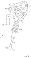
- valve train 1 according to an embodiment of the present invention in a schematic view for ease of understanding in a plan view.
- the valve drive 1 has a drive shaft 2, which is rotated by the base engine, not shown, via a drive in the form of a chain or a toothed belt or the like in rotation.
- the drive shaft 2 is shown with only one cam 3, but may be the drive shaft with cams of a multi-cylinder internal combustion engine, so that it is readily apparent that the drive shaft 2 may have a plurality of cams 3.
- the valve drive 1 shown can thus serve for the inlet control of a multi-cylinder multi-valve internal combustion engine.
- the cam 3 now follows a cam follower component or first transmission element 4 in the form of a pivoting lever.
- a rolling element 5 is rotatably arranged in the form of a roller on the pivot lever 4, so that it comes between the cam 3 and the roller 5 to a rolling operation.
- the pivot lever 4 has in the region of the bearing of the roller 5 a bore or receptacle 6, in which a spring arm 7 of a torsion spring 8 engages.
- the torsion spring 8 is received in a made of a plastic material holder 9, wherein for receiving the torsion spring 8, the holder 9 is formed in two parts and by latching the two housing halves of the holder 9, the torsion spring 8 is fixed in the holder 9.
- the thus created unit of torsion spring 8 and holder 9 can now be rotatably mounted on a bearing portion of the drive shaft or camshaft 2.
- the pivot lever 4 can be displaced by 180 degrees from the full-load basic position of the valve drive shown in FIGS. 1 and 2 of the drawing into a neutral basic position shown in FIGS. 3 to 6 by means of a rotation of an eccentric shaft 10, wherein the in FIGS. 1 and 2 of FIG Drawing shown full load position of the idle position shown in Fig. 3 and 4 in particular differs in that the point of contact between a formed on the pivot lever 4 and a control cam arranged on a second transmission element 12 roller 13 from the designated with HR Hubrampenab mustard the control curve 11 migrates to the NH designated Nullhubabexcellent the cam 11.
- the second transmission element 12 in the form of a finger lever can press on a valve stem 15 for actuation of a gas exchange valve 14 and is supported at its end 16 opposite the valve stem 15 at, for example, a hydraulically operating valve clearance compensation element 17.
- the gas exchange valve 14 is axially guided with its valve stem 15 in a valve stem guide 18 which may be pressed into a cylinder head, not shown, and is kept closed in an unopened state by means of a coil spring 19, so that the valve disc 20 against a in the cylinder head of Internal combustion engine arranged valve seat presses.
- the holder 9 is rotatably mounted at a bearing point of the drive shaft or camshaft 2, so that a rotation of the camshaft 2 does not lead to a deflection of the spring arm 7 with respect to the center axis 21 of the torsion spring 8, as long as the cam 3 rolls with its base circle on the roller 5. Since the torsion spring 8 exerts a biasing force in the basic position shown in FIG. 1, the roller 5 is pressed against the cam 3 by this pretensioning force.
- this position of the valve train 1 was achieved in that the cam 3 come into contact with the cam 5 with its cam elevation curve 22 is and thus has acted upon the pivot lever 4 in the direction of the gas exchange valve 14 out.
- the pivoting movement of the pivoting lever 4 leads to a shift of the contact point between the Hubrampenabrisk HR of the control cam 11 and the roller 13, so that the valve play compensating element 17 supporting cam followers 12 directed towards the valve stem 15 of the gas exchange valve 14 is directed downward and thus the gas exchange valve 14th in an open position presses (in Fig. 2 is the sake of simplicity, the coil spring 19th has been omitted), so that the gas exchange valve 14 is open with maximum lift height for gas exchange operation.
- the spring arm 7 of the torsion spring 8 is biased and keeps the roller 5 in contact with the cam third
- FIG. 3 of the drawing shows now the valve gear 1 in the neutral position corresponding to a basic position with the torsion spring 8 in basic position.
- the eccentric shaft 10 has been rotated by 180 degrees, which leads to a displacement of the pivot lever 4 along the control cam 11 in the designated zero NH range.
- the included between the center axis 21 and a along the center axis of the spring arm 7 reference axis 23 included angle ⁇ by the displacement of the pivot lever 4 along the control cam 11 in the area of the zero stroke section of the control cam 11 is not changed.
- the base of the torsion spring 8 corresponding biasing force is maintained, so that no change in the friction conditions in the valve train 1 has resulted from the displacement of the pivot lever 4.
- Fig. 4 of the drawings now shows a representation similar to FIG. 3 with a rotated cam, so that the gas exchange valve 14 performs a valve lift, which is sufficient to maintain the idle speed of the internal combustion engine.
- the valve lift of the gas exchange valve in the full load position is 12 mm, for example, the valve lift in the idling position may be reduced to a value of, for example, 1.5 mm.
- the biasing force generated in the deflected by the rotation of the cam 3 and tensioned position of the torsion spring 8 corresponds to the biasing force of the torsion spring 8 in the illustrated in Fig. 2 deflected position in full load operation.
- FIG. 5 of the drawings shows the valve train 1 in a position to effect selective cylinder deactivation.
- This position was realized by a further displacement of the pivot lever 4 along the zero lift curve NH of the control cam 11 by means of the application of a piston / cylinder unit 24 with, for example, pressure oil from the engine lubricating oil circuit.
- the application of the piston / cylinder unit 24 now leads to a displacement brought about by the displacement of the pivoting lever 4 due to the rotation of the eccentric shaft 10, which is additively superimposed on a further displacement of the pivoting lever 4 brought about by the piston / cylinder unit 24 such that the point of contact between the Control cam 11 and the roller 13 has been moved to the end of the zero lift NH.
- the biasing force generated by the torsion spring 8 corresponds to those of the torsion spring 8 in the tensioned state in idle position of the valve gear 1 and in tensioned state in full load position of the valve train 1 is generated.
- the biasing force of the torsion spring 8 changes in each of the cam 3 not actuated basic position or actuated by the cam 3 deflected biased position not in response to the displacement of the pivot lever 4 and thus not in response to the desired or realized valve lift ,
Landscapes
- Engineering & Computer Science (AREA)
- Mechanical Engineering (AREA)
- General Engineering & Computer Science (AREA)
- Valve Device For Special Equipments (AREA)
- Valve-Gear Or Valve Arrangements (AREA)
Abstract
Description
Die vorliegende Erfindung betrifft einen Ventiltrieb einer Brennkraftmaschine nach dem Oberbegriff des Anspruchs 1.The present invention relates to a valve train of an internal combustion engine according to the preamble of claim 1.
Ventiltriebe für Brennkraftmaschinen sind bereits in vielfachen Ausführungsformen bekannt geworden. Bei seit langer Zeit bekannten Ventiltrieben ist es weder möglich, den Ventilhub, noch die Ventilöffnungszeit während des Betriebs der Brennkraftmaschine zu verändern. Neben variablen Ventiltrieben, bei denen beispielsweise die Phasenlage, der Ventilhub, die Steilheit der Öffnungs- und Schließflanke oder auch die Öffnungsdauer modifiziert werden kann, sind den jeweiligen Anforderungen der damit betriebenen Brennkraftmaschinen entsprechende Ventiltriebe bekannt geworden, die eine geringere Parametervariation zulassen, dafür aber konstruktiv einfacher ausgebildet sind.Valve trains for internal combustion engines have already become known in many embodiments. When known for a long time valve trains, it is not possible to change the valve lift, nor the valve opening time during operation of the internal combustion engine. In addition to variable valve trains in which, for example, the phase position, the valve lift, the steepness of the opening and closing edge or the opening period can be modified, the respective requirements of the thus operated internal combustion engine corresponding valve trains have become known that allow a smaller parameter variation, but constructive are formed simpler.
Ein Beispiel eines Ventiltriebs für eine Brennkraftmaschine, mit dem die Ventilöffnungsdauer variiert werden kann, ist in der Europäischen Patentschrift EP 0 865 566 B1 beschrieben. Ein weiteres Beispiel eines variablen Ventiltrieb für eine Brennkraftmaschine ist in der auf die Anmelderin zurückgehenden unveröffentlichten Deutschen Patentanmeldung 102 37 104 beschrieben.An example of a valve train for an internal combustion engine, with which the valve opening duration can be varied, is described in the European patent EP 0 865 566 B1. Another example of a variable valve train for an internal combustion engine is described in the unpublished German patent application 102 37 104, which is based on the applicant.
Diese Patentanmeldung beschreibt einen Ventiltrieb für eine Brennkraftmaschine, mit dem die Höhe des Hubs der Gaswechselventile verändert werden kann. Die Veränderung der Hubhöhe kann dabei beispielsweise in Abhängigkeit von der Lastsituation der Brennkraftmaschine modifiziert werden. So kann mit dem beschriebenen Ventiltrieb eine Volllaststeuerung erreicht werden, d.h. die Ventilhubhöhe maximiert werden und beispielsweise einen Wert von etwa 12 mm einnehmen und auch ein Ventilhub realisiert werden, der der Leerlaufstellung entspricht. Darüber hinaus ist es auch möglich, eine zylinderselektive Nullhubhöhe einzustellen, also eine Zylinderabschaltung zu realisieren.This patent application describes a valve train for an internal combustion engine, with which the height of the stroke of the gas exchange valves can be changed. The change in the lifting height can, for example, depending on the Load situation of the internal combustion engine to be modified. Thus, with the valve train described a full load control can be achieved, ie the valve lift can be maximized and take, for example, a value of about 12 mm and also a valve lift can be realized, which corresponds to the neutral position. In addition, it is also possible to set a cylinder-selective zero-stroke height, ie to realize a cylinder deactivation.
Bei dem genannten Ventiltrieb wird mittels einer Antriebswelle mit Nockenprofilen ein erstes Übertragungselement so betätigt, dass eine Drehbewegung der Nocken zu einer Schwenkbewegung des ersten Übertragungselements führt, wobei die Schwenkbewegung des ersten Übertragungselements über ein zweites Übertragungselement letztlich zum Öffnen des jeweiligen Gaswechselventils unter Überwindung der Federkraft einer am Ventilschaft abgestützten Schraubendruckfeder führt. Über eine Verdrehung einer Exzenterwelle , die als Stellelement wirkt, kann das erste Übertragungselement nun relativ zum zweiten Übertragungselement an einer Steuerkurve verlagert bzw. verschoben werden, so dass sich der Kontaktpunkt zwischen dem ersten und dem zweiten Übertragungselement entlang der Steuerkurve verschiebt. Die Steuerkurve ist nun so ausgebildet, dass sie einen Nullhubkurvenbereich besitzt und einen Hubrampenabschnitt, so dass mittels der Verschiebung des Kontaktpunkts zwischen dem ersten und dem zweiten Übertragungselement an den beiden Abschnitten ein veränderbarer Ventilhub erreicht wird, der bis zum der Leerlaufstellung des Verbrennungsmotors entsprechenden Ventilhubhöhe modifiziert werden kann.In the case of the valve drive mentioned, a first transmission element is actuated by means of a drive shaft with cam profiles such that a rotational movement of the cams leads to a pivoting movement of the first transmission element, whereby the pivoting movement of the first transmission element via a second transmission element ultimately opens the respective gas exchange valve by overcoming the spring force on the valve stem supported helical compression spring leads. About a rotation of an eccentric shaft, which acts as an actuating element, the first transmission element can now be displaced or displaced relative to the second transmission element on a control cam, so that shifts the contact point between the first and the second transmission element along the control curve. The control cam is now designed so that it has a Nullhubkurvenbereich and a Hubrampenabschnitt, so that by means of the displacement of the contact point between the first and the second transmission element at the two sections a variable valve lift is achieved, which modifies to the idling position of the engine corresponding valve lift can be.
Die von der Antriebswelle und der oder den daran angeordneten Nocken erzeugte Ventilöffnungskraft wird über die beiden Übertragungselemente auf den Ventilschaft übertragen, so dass es zur Herbeiführung einer definierten Lage des ersten Übertragungselements an der Nocke zweckmäßig ist, eine Vorspannkraft zwischen dem ersten Übertragungselement und der Nocke aufzubauen.The valve opening force generated by the drive shaft and the cam or cams disposed thereon is transmitted to the valve stem via the two transmission elements, so that it is expedient to establish a biasing force between the first transmission element and the cam to bring about a defined position of the first transmission element on the cam ,
Da es damit aufgrund der Relativbewegung zwischen der Nocke und dem Nockenfolgebauteil in der Form des ersten Übertragungselements zu Reibung zwischen der Nocke und dem ersten Übertragungselement kommt, liegt der vorliegenden Erfindung nunmehr die Aufgabe zugrunde, einen Ventiltrieb einer Brennkraftmaschine zu schaffen, mit dem einerseits eine variable Ventilhubhöhe realisierbar ist und andererseits den Anforderungen an ein möglichst günstiges Reibungsverhalten zwischen der Nocke und dem Nockenfolgeglied Rechnung getragen wird.Since, due to the relative movement between the cam and the cam follower in the form of the first transmission element, friction between the cam and the first transmission element occurs, the present invention is Invention now the object of the invention to provide a valve train of an internal combustion engine, with the one hand, a variable valve lift height can be realized and on the other hand, the requirements for the best possible friction behavior between the cam and the cam follower account is taken.
Die Erfindung schafft nunmehr zur Lösung dieser Aufgabe einen Ventiltrieb mit den Merkmalen des Anspruchs 1. Vorteilhafte Ausgestaltungen hiervon sind in den weiteren Ansprüchen beschrieben.The invention now provides for solving this problem a valve train with the features of claim 1. Advantageous embodiments thereof are described in the further claims.
Die Erfindung sieht einen Ventiltrieb einer Brennkraftmaschine vor, wobei der Ventiltrieb eine drehbare Antriebswelle besitzt mit wenigstens einer Nocke und ein damit betätigbares erstes Übertragungselement aufweist, welches mit einem zweiten Übertragselement in Wirkverbindung steht derart, dass dieses einen Schaft eines Gaswechselventils beaufschlagen kann nämlich derart, dass eine Verlagerung des ersten Übertragungselements entlang einer zwischen dem ersten und dem zweiten Übertragungselement ausgebildeten Steuerkurve zu einer Veränderung der Hubhöhe des beaufschlagten Gaswechselventils führt und die Verlagerung des ersten Übertragungselements mittels einer Verdrehung einer Welle und/oder der Betätigung eines Stellantriebs erfolgt und ein elastisches Bauteil das erste Übertragungselement zum Kontakt mit der Nocke beaufschlägt und dieses elastische Bauteil derart angeordnet ist, dass die vom elastischen Bauteil erzeugte Vorspannkraft von der Verlagerung des ersten Übertragungselements relativ zu zweiten Übertragungselement unabhängig ist.The invention provides a valve train of an internal combustion engine, wherein the valve drive has a rotatable drive shaft having at least one cam and a first transmission element operable therewith, which is operatively connected to a second transfer element such that this can act on a shaft of a gas exchange valve such that a displacement of the first transmission element along a control curve formed between the first and the second transmission element leads to a change in the lift height of the acted gas exchange valve and the displacement of the first transmission element by means of a rotation of a shaft and / or the actuation of an actuator and an elastic member is the first Actuates transfer element for contact with the cam and this elastic member is arranged such that the biasing force generated by the elastic member of the displacement of the first Übertr Acting element is independent relative to the second transmission element.
Die Erfindung schafft damit einen hubvariablen Ventiltrieb, bei dem die Ventilhubhöhe in einem weiten Bereich zwischen einer Volllaststellung mit maximalem Ventilhub und einer Leerlaufgasstellung mit minimalem Ventilhub bzw. einer Zylinderabschaltstellung mit Nullventilhub verändert werden kann und dabei das das erste Nockenfolgeelement bildende erste Übertragungselement von einem elastischen Bauteil so gegen die Nocke zum Kontakt mit dieser beaufschlagt wird, dass die von dem elastischen Bauteil erzeugte Vorspannkraft von der zur Herbeiführung der Veränderung des Hubs des Gaswechselventils notwendigen Verlagerung des ersten Übertragungselements relativ zum zweiten Übertragungselement unabhängig ist.The invention thus provides a variable-stroke valve drive, in which the valve lift can be varied in a wide range between a full load position with maximum valve lift and a Leerlaufgasstellung with minimum valve or a Zylinderabschaltstellung Nullventilhub and thereby forming the first cam follower first transmission element of an elastic member is urged against the cam for contact with this, that the biasing force generated by the elastic member of the necessary for effecting the change of the stroke of the gas exchange valve displacement of the first transmission element is independent relative to the second transmission element.
Damit wird in vorteilhafter Weise erreicht, dass unabhängig von der Stellung des ersten Übertragungselements relativ zum zweiten Übertragungselement die vom elastischen Bauteil erzeugte Vorspannkraft aufgetragen über dem Nockenwinkel gleiche Werte einnimmt und nicht durch eine Relativbewegung des ersten Übertragungselements relativ zum zweiten Übertragungselement verändert wird, so dass bei vergleichbaren Nockenwinkeln eine gleiche Vorspannkraft und damit Flächenpressung zwischen der Nocke und dem ersten Übertragungselement als Nockenfolgebauteil besteht, ohne dass hierbei durch eine Verlagerung des ersten Übertragungselements relativ zum zweiten Übertragungselement eine Abhängigkeit in den Verlauf der Vorspannkraft eingeführt wird. Da damit die Vorspannkraft nicht von der Verlagerung des ersten Übertragungselements relativ zum zweiten Übertragungselement abhängt, führt diese Verlagerung auch nicht zu einer verlagerungsabhängigen Reibleistung zwischen den Wälzpartnern Nocke und Nockenfolgebauteil, also dem ersten Übertragungselement.This is achieved in an advantageous manner that regardless of the position of the first transmission element relative to the second transmission element applied by the elastic component biasing force applied over the cam angle assumes the same values and is not changed by a relative movement of the first transmission element relative to the second transmission element, so that at Comparable cam angles a same biasing force and thus surface pressure between the cam and the first transmission element as a cam follower component, without this being introduced by a displacement of the first transmission element relative to the second transmission element, a dependence in the course of the biasing force. Since thus the biasing force does not depend on the displacement of the first transmission element relative to the second transmission element, this displacement also does not lead to a displacement-dependent friction between the Wälzpartnern cam and follower cam component, so the first transmission element.
Nach einer vorteilhaften Weiterbildung der Erfindung ist es vorgesehen, dass das elastische Bauteil an der Antriebswelle relativ zu dieser drehbar angeordnet ist und zwar kann dies mittels eines an der Antriebswelle drehbar angeordneten Halters erreicht werden, der das elastische Bauteil aufnimmt und hält.According to an advantageous embodiment of the invention, it is provided that the elastic member is rotatably mounted on the drive shaft relative to this and that this can be achieved by means of a rotatably mounted on the drive shaft holder, which receives and holds the elastic member.
In Weiterbildung der Erfindung ist dabei vorgesehen, dass das erste Übertragungselement ein Schwenkhebel ist, an dem ein Wälzkörper drehbar gelagert ist, der sich mit der Nocke der drehbaren Antriebswelle in Wälzeingriff befindet. Damit wird zwischen dem Wälzkörper des Schwenkhebels und der Nocke eine Rollbedingung realisiert, die positiv zum Ziel der Verringerung der Reibleistung beiträgt.In a further development of the invention it is provided that the first transmission element is a pivot lever, on which a rolling body is rotatably mounted, which is in rolling contact with the cam of the rotatable drive shaft. Thus, a rolling condition is realized between the rolling elements of the pivot lever and the cam, which contributes positively to the goal of reducing the friction power.
Nach einer vorteilhaften Ausgestaltung gemäss der Erfindung kann das elastische Bauteil eine Drehfeder sein, die von dem an der Antriebswelle drehbar angeordneten Halter aufgenommen ist und einen Federarm aufweist, der in eine Bohrung des Schwenkhebels eingreift und somit den Wälzkörper am Schwenkhebel in Kontakt mit der Nocke hält.According to an advantageous embodiment according to the invention, the elastic member may be a torsion spring which is received by the holder rotatably mounted on the drive shaft and having a spring arm, which in a bore engages the pivot lever and thus keeps the rolling elements on the pivot lever in contact with the cam.
Wenn nun die Nocke mit ihrem Nockenerhebungsprofil mit dem Wälzkörper in Kontakt kommt, wird die zwischen der Antriebswelle und dem Schwenkhebel angeordnete Drehfeder gespannt, so dass die Drehfeder dafür sorgt, dass nach dem Wegdrehen des Nockenerhebungsprofils aus dem Kontakt mit dem Wälzkörper der Wälzkörper gegen den Nockengrundkreis gedrückt wird und somit der Wälzkörper in Kontakt mit der Nocke verbleibt.Now, when the cam with its cam lobe profile comes into contact with the rolling element, the arranged between the drive shaft and the pivot lever torsion spring is stretched, so that the torsion spring ensures that after the turning away of the cam lobe profile from the contact with the rolling elements of the rolling elements against the cam base circle is pressed and thus the rolling element remains in contact with the cam.
Nach einer Weiterbildung der Erfindung ist es vorgesehen, dass die vorstehend genannte Steuerkurve am Schwenkhebel ausgebildet ist und eine Nullhubkurve aufweist sowie einen Hubrampenabschnitt besitzt und der so ausgebildete Schwenkhebel entlang der Steuerkurve an einem am zweiten Übertragungselement drehbar angeordneten Wälzkörper verlagerbar ist. Es bedeutet dies mit anderen Worten, dass der Schwenkhebel entlang der Steuerkurve an dem Wälzkörper des zweiten Übertragungselements verschoben werden kann, so dass sich der Kontaktpunkt zwischen dem Schwenkhebel bzw. der am Schwenkhebel ausgebildeten Steuerkurve und dem Wälzkörper im Bereich zwischen der Nullhubkurve und dem Hubrampenabschnitt befindet, so dass dann, wenn sich der Kontaktpunkt im Bereich der Nullhubkurve befindet eine zylinderselektive Ventilabschaltung und damit Zylinderabschaltung realisiert werden kann und dann, wenn sich der Kontaktpunkt im Bereich des Hubrampenabschnitts der Steuerkurve befindet, eine Veränderung des Hubs des Gaswechselventils realisiert werden kann, je nach der Position des Kontaktpunkts entlang des Hubrampenabschnitts bzw. dessen geometrischer Ausbildung.According to a development of the invention, it is provided that the above-mentioned control cam is formed on the pivot lever and has a Nullhubkurve and has a Hubrampenabschnitt and the pivoting lever thus formed along the control cam on a second transmission element rotatably arranged rolling elements is displaced. In other words, this means that the pivoting lever can be displaced along the control cam on the rolling body of the second transmission element, so that the contact point between the pivoting lever or the control cam formed on the pivot lever and the rolling element is in the region between the zero-stroke curve and the lifting ramp section so that, when the contact point is in the zero-stroke curve, a cylinder-selective valve deactivation and thereby cylinder deactivation can be realized, and when the contact point is in the range of the lift ramp portion of the control cam, a change in the lift of the gas exchange valve can be realized, as appropriate the position of the contact point along the Hubrampenabschnitts or its geometric design.
Nach einer Weiterbildung der Erfindung ist es vorgesehen, dass die Welle zur Verlagerung des ersten Übertragungselements relativ zum zweiten Übertragüngselement eine Exzenterwelle ist und mittels einer Verdrehung der Exzenterwelle eine Verlagerung des Schwenkhebels am Wälzkörper des zweiten Übertragungselements entlang der Steuerkurve um einen vorbestimmten Abstand möglich ist. Damit kann durch eine Verdrehung der Exzenterwelle eine beispielsweise zylinderbankselektive Grundabstimmung der Hubhöhe der Gaswechselventil dieser Zylinderbank erreicht werden.According to a development of the invention, it is provided that the shaft for displacing the first transmission element relative to the second Übertragungsüngselement is an eccentric shaft and displacement of the pivot lever on the rolling elements of the second transmission element along the control cam by a predetermined distance is possible by means of a rotation of the eccentric shaft. Thus, by a rotation of the eccentric shaft, for example, a cylinder bank selective Basic tuning of the lifting height of the gas exchange valve of this cylinder bank can be achieved.
Mittels einer Betätigung eines der Exzenterwelle nachgeschalteten Stellantriebs in der Form einer Kolben/Zylindereinheit kann eine Verlagerung des Schwenkhebels am Wälzkörper des zweiten Übertragungselements entlang der Steuerkurve um einen wiederum vorbestimmten Abstand erfolgen, die der mittels der Exzenterwelle herbeigeführten Verlagerung additiv überlagert werden kann. Es bedeutet dies mit anderen Worten, dass je nach Stellung des Stellantriebs die über die Exzenterwelle herbeigeführte Verlagerung beispielsweise kompensiert werden kann oder durch die Betätigung des Stellantriebs eine in Richtung der Verlagerung des Schwenkhebels am zweiten Übertragungselement mit gleichem Richtungsvorzeichen additiv überlagerte erweiterte Verlagerung des Schwenkhebels am Wälzkörper des zweiten Übertragungselements realisiert werden kann, mit der beispielsweise eine Verschiebung des Kontaktpunkt der Steuerkurve am Schwenkhebel zum Wälzkörper des zweiten Übertragungselements realisiert werden kann, bis in den Bereich der Nullhubkurve der Steuerkurve selbst und somit eine zylinderselektive Zylinderabschaltung durch den erfindungsgemäßen Ventiltrieb realisiert werden kann.By means of an actuation of an eccentric shaft downstream actuator in the form of a piston / cylinder unit, a displacement of the pivot lever on the rolling elements of the second transmission element along the control curve can take place by a predetermined distance, which can be superimposed additively the displacement induced by the eccentric shaft. In other words, this means that depending on the position of the actuator, the displacement caused by the eccentric shaft can be compensated, for example, or by the actuation of the actuator in the direction of displacement of the pivot lever on the second transmission element with the same direction additive superimposed extended displacement of the pivot lever on the rolling elements of the second transmission element can be realized with the example, a shift of the contact point of the control cam on the pivot lever to the rolling elements of the second transmission element can be realized in the range of Nullhubkurve the cam itself and thus a cylinder-selective cylinder shutdown by the valve gear according to the invention.
Nach einer vorteilhaften Ausführungsform ist es vorgesehen, dass der vorstehend genannte Halter aus einem Kunststoffwerkstoff gefertigt ist, an dem die Drehfeder beispielsweise mittels einer Rastverbindung lösbar festgelegt werden kann. Durch eine drehbare Anordnung des die Drehfeder haltenden Halters an der Antriebswelle wird damit erreicht, dass die Drehfeder so zwischen der Antriebswelle und dem Wälzkörper des Schwenkhebels eingespannt ist, dass die von der Drehfeder erzeugte Federkraft von einer Verlagerung des Schwenkhebels relativ zum zweiten Übertragungselement unabhängig ist.According to an advantageous embodiment, it is provided that the above-mentioned holder is made of a plastic material, on which the torsion spring can be releasably fixed, for example by means of a latching connection. By a rotatable arrangement of the torsion spring holding holder on the drive shaft is achieved so that the torsion spring is clamped between the drive shaft and the rolling elements of the pivot lever, that the spring force generated by the torsion spring is independent of a displacement of the pivot lever relative to the second transmission element.
Damit bleibt die Vorspannkraft, mit der der Wälzkörper des Schwenkhebels gegen die Nocke der Antriebswelle gedrückt wird, unabhängig von der Verlagerung des Schwenkhebels relativ zum zweiten Übertragungselement. Das geometrische Verhältnis zwischen der Mitte der Nockenwelle, einem Drehpunkt des Federarms der Drehfeder und der Mitte des Wälzkörpers des Schwenkhebels bleibt somit unabhängig von der Lage des Schwenkhebels immer gleich und damit die Vorspannkraft bzw. die zu überwindende Reibleistung.Thus, the biasing force with which the rolling elements of the pivot lever is pressed against the cam of the drive shaft, regardless of the displacement of the pivot lever relative to the second transmission element. The geometric relationship between the center of the camshaft, a pivot point of the spring arm The torsion spring and the center of the rolling element of the pivot lever thus remains independent of the position of the pivot lever always the same and thus the biasing force or to be overcome friction.
Die Erfindung wird im Folgenden anhand der Zeichnung näher erläutert. Diese zeigt in:
- Fig. 1 einen Ventiltrieb gemäß einer Ausführungsform nach der vorliegenden Erfindung in Volllaststellung mit einer Drehfeder in Grundstellung;
- Fig. 2 eine Volllaststellung ähnlich Fig. 1 mit aufgrund der Drehung der Nocke gespannter Drehfeder und betätigtem Gaswechselventil;
- Fig. 3 dem Ventiltrieb in einer Leerlaufstellung mit Drehfeder in Grundstellung und unbetätigtem Gaswechselventil;
- Fig. 4 eine Abbildung ähnlich Fig. 3 mit Ventiltrieb in Leerlaufstellung mit aufgrund der Drehung der Nocke gespannter Drehfeder und betätigtem Gaswechselventil;
- Fig. 5 einen Ventiltrieb in einer Stellung zur Herbeiführung einer Zylinderabschaltung mit Drehfeder in Grundstellung; und
- Fig. 6 eine Darstellung ähnlich Fig. 5 mit aufgrund der Drehung der Nocke gespannter Drehfeder und unbetätigtem Gaswechselventil.
- 1 shows a valve train according to an embodiment of the present invention in full load position with a torsion spring in basic position.
- Fig. 2 is a full load position similar to Figure 1 with due to the rotation of the cam tensioned torsion spring and actuated gas exchange valve.
- 3 shows the valve drive in an idle position with torsion spring in the basic position and unconfirmed gas exchange valve.
- 4 is an illustration similar to Figure 3 with valve train in neutral position with due to the rotation of the cam tensioned torsion spring and actuated gas exchange valve.
- 5 shows a valve drive in a position for bringing about a cylinder deactivation with a torsion spring in the basic position; and
- Fig. 6 is a view similar to Fig. 5 with due to the rotation of the cam tensioned torsion spring and unactuated gas exchange valve.
Nachfolgend folgt nun zunächst eine Beschreibung des Ventiltriebs unter Bezugnahme auf Fig. 1 der Zeichnung, wobei die hier eingeführten Bezugszeichen auch für die weiteren Figuren gelten.Below follows a description of the valve train with reference to Fig. 1 of the drawing, wherein the reference numbers introduced here apply to the other figures.
Fig. 1 der Zeichnung zeigt nun einen Ventiltrieb 1 gemäß einer Ausführungsform nach der vorliegenden Erfindung in einer zur Erleichterung des Verständnisses schematischen Darstellung in einer Draufsichtansicht.1 of the drawings now shows a valve train 1 according to an embodiment of the present invention in a schematic view for ease of understanding in a plan view.
Der Ventiltrieb 1 weist eine Antriebswelle 2 auf, die vom nicht dargestellten Grundmotor über einen Antrieb in der Form einer Kette oder eines Zahnriemens oder dergleichen in Drehung versetzt wird. In den Figuren ist die Antriebswelle 2 jeweils mit nur einer Nocke 3 dargestellt, kann aber die Antriebswelle mit Nocken einer mehrzylindrigen Brennkraftmaschine sein, so dass es ohne weiteres klar ist, dass die Antriebswelle 2 eine Vielzahl von Nocken 3 besitzen kann. Der dargestellte Ventiltrieb 1 kann somit zur Einlasssteuerung einer mehrzylindrigen mehrventiligen Brennkraftmaschine dienen.The valve drive 1 has a
Der Nocke 3 folgt nun ein Nockenfolgebauteil oder erstes Übertragungselement 4 in der Form eines Schwenkhebels.The
An dem der Nocke 3 zugewandten Ende des Schwenkhebels 4 ist ein Wälzkörper 5 in der Form einer Laufrolle am Schwenkhebel 4 drehbar angeordnet, so dass es zwischen der Nocke 3 und der Laufrolle 5 zu einer Rollbedienung kommt. Der Schwenkhebel 4 weist im Bereich der Lagerung der Laufrolle 5 eine Bohrung oder Aufnahme 6 auf, in die ein Federarm 7 einer Drehfeder 8 eingreift. Die Drehfeder 8 ist dabei in einem aus einem Kunststoffwerkstoff gefertigten Halter 9 aufgenommen, wobei zur Aufnahme der Drehfeder 8 der Halter 9 zweiteilig ausgebildet ist und durch miteinander Verrasten der beiden Gehäusehälften des Halters 9 die Drehfeder 8 im Halter 9 festgelegt wird. Die so geschaffene Einheit aus Drehfeder 8 und Halter 9 kann nun an einem Lagerabschnitt der Antriebswelle oder Nockenwelle 2 drehbar befestigt werden.At the
Der Schwenkhebel 4 kann mittels einer Drehung einer Exzenterwelle 10 um 180 Grad aus der in Fig. 1 und 2 der Zeichnung dargestellten Volllastgrundstellung des Ventiltriebs in eine in Fig. 3 bis 6 dargestellte Leerlaufgrundstellung verlagert werden, wobei sich die in Fig. 1 und 2 der Zeichnung dargestellte Volllaststellung von der in Fig. 3 und 4 dargestellten Leerlaufstellung insbesondere dadurch unterscheidet, dass der Kontaktpunkt zwischen einer am Schwenkhebel 4 ausgebildeten Steuerkurve und einer an einem zweiten Übertragungselement 12 angeordneten Laufrolle 13 aus dem mit HR bezeichneten Hubrampenabschnitt der Steuerkurve 11 in den mit NH bezeichneten Nullhubabschnitt der Steuerkurve 11 wandert.The
Das zweite Übertragungselement 12 in der Form eines Schlepphebels kann zur Betätigung eines Gaswechselventils 14 auf einen Ventilschaft 15 drücken und stützt sich an seinem dem Ventilschaft 15 gegenüberliegenden Ende 16 an einem beispielsweise hydraulisch arbeitenden Ventilspielausgleichselement 17 ab.The
Das Gaswechselventil 14 wird mit seinem Ventilschaft 15 in einer Ventilschaftführung 18, die in einem nicht näher dargestellten Zylinderkopf eingepresst sein kann, axial geführt und wird in einem ungeöffneten Zustand mittels einer Schraubenfeder 19 geschlossen gehalten, so dass sich der Ventilteller 20 gegen einen im Zylinderkopf der Brennkraftmaschine angeordneten Ventilsitz drückt.The
Wie es vorstehend bereits erwähnt wurde, ist der Halter 9 an einer Lagerstelle der Antriebswelle oder Nockenwelle 2 drehbar gelagert, so dass eine Verdrehung der Nockenwelle 2 nicht zu einer Auslenkung des Federarms 7 bezogen auf die Mittenachse 21 der Drehfeder 8 führt, so lange die Nocke 3 mit ihrem Grundkreis an der Laufrolle 5 abrollt. Da die Drehfeder 8 in der in Fig. 1 dargestellten Grundstellung eine Vorspannkraft ausübt, wird von dieser Vorspannkraft die Laufrolle 5 an die Nocke 3 gedrückt.As already mentioned above, the
Fig. 2 der Zeichnung zeigt nun den Ventiltrieb 1 in Volllaststellung mit ausgelenkter und gespannter Drehfeder 8. Wie es ohne weiteres ersichtlich ist, wurde diese Stellung des Ventiltriebs 1 dadurch erreicht, dass die Nocke 3 mit ihrer Nockenerhebungskurve 22 mit der Laufrolle 5 in Kontakt gekommen ist und somit den Schwenkhebel 4 in Richtung zum Gaswechselventil 14 hin beaufschlagt hat. Die Verschwenkbewegung des Schwenkhebels 4 führt zu einer Verschiebung des Kontaktpunkts zwischen dem Hubrampenabschnitt HR der Steuerkurve 11 und der Laufrolle 13, so dass der sich am Ventilspielausgleichselement 17 abstützende Schlepphebel 12 in Richtung zum Ventilschaft 15 des Gaswechselventils 14 nach unten gerichtet bewegt und damit das Gaswechselventil 14 in eine Öffnungsstellung drückt (in Fig. 2 ist der Einfachheit halber die Schraubenfeder 19 weggelassen worden), so dass das Gaswechselventil 14 mit maximaler Hubhöhe zum Gaswechselvorgang offen steht. Durch die Drehbewegung der Nocke 3 wird der Federarm 7 der Drehfeder 8 vorgespannt und hält die Laufrolle 5 in Kontakt mit der Nocke 3.As it is readily apparent, this position of the valve train 1 was achieved in that the
Fig. 3 der Zeichnung zeigt nun den Ventiltrieb 1 in der einer Leerlaufstellung entsprechenden Grundstellung mit der Drehfeder 8 in Grundstellung. Zur Herbeiführung der Leerlaufstellung wurde die Exzenterwelle 10 um 180 Grad gedreht, was zu einer Verlagerung des Schwenkhebels 4 entlang der Steuerkurve 11 in den mit NH bezeichneten Nullhubbereich führt. Wie es ohne weiteres anhand von Fig. 3 im Vergleich zu Fig. 1 ersichtlich ist, hat sich der zwischen der Mittenachse 21 und einer entlang der Mittenachse des Federarms 7 gezeichneten Bezugsachse 23 eingeschlossene Winkel α durch die Verlagerung des Schwenkhebels 4 entlang der Steuerkurve 11 in den Bereich des Nullhubabschnitts der Steuerkurve 11 nicht verändert. Damit bleibt die der Grundstelle der Drehfeder 8 entsprechende Vorspannkraft erhalten, so dass sich durch die Verlagerung des Schwenkhebels 4 keine Veränderung der Reibungsverhältnisse im Ventiltrieb 1 ergeben hat.Fig. 3 of the drawing shows now the valve gear 1 in the neutral position corresponding to a basic position with the
Fig. 4 der Zeichnung zeigt nun eine Darstellung ähnlich Fig. 3 mit gedrehter Nocke, so dass das Gaswechselventil 14 einen Ventilhub ausführt, der ausreichend ist zur Aufrechterhaltung der Leerlaufdrehzahl der Brennkraftmaschine. Wenn lediglich als Beispiel genannt der Ventilhub des Gaswechselventils in der Volllaststellung beispielsweise 12 mm beträgt, so kann der Ventilhub in der Leerlaufstellung auf einen Wert von beispielsweise 1,5 mm verringert worden sein. Die in der durch die Drehung der Nocke 3 ausgelenkten und gespannten Stellung der Drehfeder 8 erzeugte Vorspannkraft entspricht der Vorspannkraft der Drehfeder 8 in der in Fig. 2 dargestellten ausgelenkten Stellung im Volllastbetrieb.Fig. 4 of the drawings now shows a representation similar to FIG. 3 with a rotated cam, so that the
Fig. 5 der Zeichnung schließlich zeigt den Ventiltrieb 1 in einer Stellung zur Herbeiführung einer selektiven Zylinderabschaltung. Diese Stellung wurde durch eine weitere Verlagerung des Schwenkhebels 4 entlang der Nullhubkurve NH der Steuerkurve 11 realisiert und zwar mittels der Beaufschlagung einer Kolben/Zylindereinheit 24 mit beispielsweise Drucköl aus dem Motorschmierölkreislauf. Die Beaufschlagung der Kolben/Zylindereinheit 24 führt nun zu einer aus der Verlagerung des Schwenkhebels 4 aufgrund der Drehung der Exzenterwelle 10 herbeigeführten Verlagerung, die eine weitere durch die Kolben/Zylindereinheit 24 herbeigeführte Verlagerung des Schwenkhebels 4 additiv soweit überlagert wird, dass der Kontaktpunkt zwischen der Steuerkurve 11 und der Laufrolle 13 an den Endbereich der Nullhubkurve NH verschoben wurde. In dieser Stellung des Ventiltriebs 1, bei der die Vorspannkraft der Drehfeder 8 in der unbetätigten Grundstellung der Vorspannkraft der Drehfeder 8 in der unbetätigten Grundstellung in der Volllaststellung des Ventiltriebs 1 und in der Leerlaufstellung des Ventiltriebs 1 entspricht (der Winkel α hat sich nicht geändert), führt eine Drehung der Nocke 3 (siehe Fig. 6 der Zeichnung) zu einem Abrollen des Kontaktpunkts zwischen der Laufrolle 13 und der Steuerkurve 11 im Bereich der Nullhubkurve NH, so dass es nicht mehr zu einer Öffnungsbeaufschlagung des Ventilschafts 15 durch den Schlepphebel 12 kommt, das Gaswechselventil 14 bleibt geschlossen, der zugehörige Zylinder der Brennkraftmaschine ist vom Gaswechselvorgang ausgeschlossen, der Zylinder ist selektiv abgeschaltet.Finally, Fig. 5 of the drawings shows the valve train 1 in a position to effect selective cylinder deactivation. This position was realized by a further displacement of the
Auch in der in Fig. 6 gezeigten, von der Nocke 3 betätigten Stellung und damit ausgelenkten und gespannten Stellung der Drehfeder 8 entspricht die von der Drehfeder 8 erzeugte Vorspannkraft derjenigen, wie sie von der Drehfeder 8 im gespannten Zustand in Leerlaufstellung des Ventiltriebs 1 und im gespannten Zustand in Volllaststellung des Ventiltriebs 1 erzeugt wird. Damit ändert sich die Vorspannkraft der Drehfeder 8 in der jeweils von der Nocke 3 nicht betätigten Grundstellung bzw. der von der Nocke 3 betätigten ausgelenkten vorgespannten Stellung nicht in Abhängigkeit von der Verlagerung des Schwenkhebels 4 und somit nicht in Abhängigkeit von dem gewünschten bzw. realisierten Ventilhub.Also in the position shown in Fig. 6, actuated by the
Hinsichtlich vorstehend im Einzelnen nicht näher erläuterter Merkmale der Erfindung wird im Übrigen ausdrücklich auf die Ansprüche und die Zeichnung verwiesen.With regard to features of the invention which are not explained in greater detail above, reference is expressly made to the claims and the drawings, moreover.
Bezugszeichenliste
- 1.
- Ventiltrieb
- 2.
- Antriebswelle
- 3.
- Nocke
- 4.
- Schwenkhebel
- 5.
- Laufrolle
- 6.
- Bohrung
- 7.
- Federarm
- 8.
- Drehfeder
- 9.
- Halter
- 10.
- Exzenterwelle
- 11.
- Steuerkurve
- 12.
- 2. Übertragungselement, Schlepphebel
- 13.
- Laufrolle
- 14.
- Gaswechselventil
- 15.
- Ventilschaft
- 16.
- Schlepphebelende
- 17.
- Ventilspielausgleichselement
- 18.
- Ventilschaftführung
- 19.
- Schraubenfeder
- 20.
- Ventilteller
- 21.
- Mittenachse
- 22.
- Nockenerhebungskurve
- 23.
- Bezugsachse
- 24.
- Kolben/Zylindereinheit
- 1.
- valve train
- Second
- drive shaft
- Third
- cam
- 4th
- pivoting lever
- 5th
- caster
- 6th
- drilling
- 7th
- spring arm
- 8th.
- torsion spring
- 9th
- holder
- 10th
- eccentric shaft
- 11th
- cam
- 12th
- 2. Transmission element, drag lever
- 13th
- caster
- 14th
- Gas exchange valve
- 15th
- valve stem
- 16th
- Drag lever end
- 17th
- Lash adjuster
- 18th
- Valve stem guide
- 19th
- coil spring
- 20th
- valve disc
- 21st
- mid-axis
- 22nd
- Cam elevation curve
- 23rd
- reference axis
- 24th
- Piston / cylinder unit
Claims (12)
Applications Claiming Priority (1)
| Application Number | Priority Date | Filing Date | Title |
|---|---|---|---|
| DE102004035005A DE102004035005A1 (en) | 2004-07-20 | 2004-07-20 | Valve gear of an internal combustion engine |
Publications (3)
| Publication Number | Publication Date |
|---|---|
| EP1619362A2 true EP1619362A2 (en) | 2006-01-25 |
| EP1619362A3 EP1619362A3 (en) | 2010-01-27 |
| EP1619362B1 EP1619362B1 (en) | 2011-04-20 |
Family
ID=35094444
Family Applications (1)
| Application Number | Title | Priority Date | Filing Date |
|---|---|---|---|
| EP05014341A Expired - Fee Related EP1619362B1 (en) | 2004-07-20 | 2005-07-01 | Valve train for an internal combustion engine |
Country Status (2)
| Country | Link |
|---|---|
| EP (1) | EP1619362B1 (en) |
| DE (2) | DE102004035005A1 (en) |
Cited By (3)
| Publication number | Priority date | Publication date | Assignee | Title |
|---|---|---|---|---|
| DE102005040959A1 (en) * | 2005-08-30 | 2007-03-08 | Bayerische Motoren Werke Ag | Hubvariabler valve drive for an internal combustion engine |
| EP2299070A1 (en) * | 2009-09-03 | 2011-03-23 | Otics Corporation | Variable valve mechanism |
| CN102061957A (en) * | 2009-11-12 | 2011-05-18 | 铃木株式会社 | Variable valve operating system for internal combustion engine |
Families Citing this family (1)
| Publication number | Priority date | Publication date | Assignee | Title |
|---|---|---|---|---|
| DE102006013915A1 (en) * | 2006-03-25 | 2007-09-27 | Daimlerchrysler Ag | Adjustment of camshaft action on motor valves uses two setting units, in contact with control curves with two degrees of freedom with relative movements between them |
Citations (3)
| Publication number | Priority date | Publication date | Assignee | Title |
|---|---|---|---|---|
| EP0686756A1 (en) | 1994-06-08 | 1995-12-13 | Bayerische Motoren Werke Aktiengesellschaft | Valve drive with variable valve opening angle control |
| US5937809A (en) | 1997-03-20 | 1999-08-17 | General Motors Corporation | Variable valve timing mechanisms |
| US6684632B2 (en) | 2000-08-09 | 2004-02-03 | Dr. Ing. H.C.F. Porsche Ag | Arrangement and method for igniting a combustible gas mixture for the exhaust system of an internal-combustion engine and corresponding exhaust system |
Family Cites Families (6)
| Publication number | Priority date | Publication date | Assignee | Title |
|---|---|---|---|---|
| DE2363891A1 (en) * | 1973-07-13 | 1975-06-26 | Daimler Benz Ag | Valve control system for ic engine - valve rod is controlled by action of lever on adjustable curved surface |
| DE2629554A1 (en) * | 1976-07-01 | 1978-01-12 | Daimler Benz Ag | Charge regulator for mixture compression engine - has valve actuator lever moved by cam with adjustable rotation centre |
| US4469056A (en) * | 1983-02-22 | 1984-09-04 | Tourtelot Jr Edward M | Dual follower variable valve timing mechanism |
| DE19913742A1 (en) * | 1999-03-26 | 2000-09-28 | Bayerische Motoren Werke Ag | Device for stroke adjustment of a gas exchange valve in the cylinder head of an internal combustion engine |
| DE10237104A1 (en) * | 2002-08-13 | 2004-02-26 | Bayerische Motoren Werke Ag | Valve drive for a piston combustion engine has a variable lift control with transmission and actuator elements fixed together |
| US6684832B1 (en) * | 2003-04-28 | 2004-02-03 | Roberto Marcelo Codina | Oscillating camshaft controlled valve operating device |
-
2004
- 2004-07-20 DE DE102004035005A patent/DE102004035005A1/en not_active Withdrawn
-
2005
- 2005-07-01 EP EP05014341A patent/EP1619362B1/en not_active Expired - Fee Related
- 2005-07-01 DE DE502005011266T patent/DE502005011266D1/en active Active
Patent Citations (3)
| Publication number | Priority date | Publication date | Assignee | Title |
|---|---|---|---|---|
| EP0686756A1 (en) | 1994-06-08 | 1995-12-13 | Bayerische Motoren Werke Aktiengesellschaft | Valve drive with variable valve opening angle control |
| US5937809A (en) | 1997-03-20 | 1999-08-17 | General Motors Corporation | Variable valve timing mechanisms |
| US6684632B2 (en) | 2000-08-09 | 2004-02-03 | Dr. Ing. H.C.F. Porsche Ag | Arrangement and method for igniting a combustible gas mixture for the exhaust system of an internal-combustion engine and corresponding exhaust system |
Cited By (4)
| Publication number | Priority date | Publication date | Assignee | Title |
|---|---|---|---|---|
| DE102005040959A1 (en) * | 2005-08-30 | 2007-03-08 | Bayerische Motoren Werke Ag | Hubvariabler valve drive for an internal combustion engine |
| EP2299070A1 (en) * | 2009-09-03 | 2011-03-23 | Otics Corporation | Variable valve mechanism |
| CN102061957A (en) * | 2009-11-12 | 2011-05-18 | 铃木株式会社 | Variable valve operating system for internal combustion engine |
| CN102061957B (en) * | 2009-11-12 | 2013-05-08 | 铃木株式会社 | Variable valve operating system for internal combustion engine |
Also Published As
| Publication number | Publication date |
|---|---|
| DE502005011266D1 (en) | 2011-06-01 |
| DE102004035005A1 (en) | 2006-02-16 |
| EP1619362B1 (en) | 2011-04-20 |
| EP1619362A3 (en) | 2010-01-27 |
Similar Documents
| Publication | Publication Date | Title |
|---|---|---|
| EP0659232B1 (en) | Variable control process and device for an internal combustion engine valve | |
| DE19960742B4 (en) | Variable valve train, preferably for internal combustion engines | |
| DE10006018B4 (en) | Variable valve drive for load control of a spark-ignited internal combustion engine | |
| WO2009152927A9 (en) | Valve train for gas exchange valves of an internal combustion engine having double-supported cam carriers | |
| EP0627043B1 (en) | Valve actuating mechanism for an internal combustion engine | |
| DE19908286A1 (en) | Variable valve control for internal combustion engine, in which each cam device can move axially on setter shaft connected to operating device | |
| DE102007010155A1 (en) | Camshaft for IC engine has two cam followers plus a circular cam which slides axially into the cam bearing for the non operating valve setting | |
| WO2005075797A1 (en) | Drag lever for deviation switching | |
| EP0521412A1 (en) | Internal combustion engine with rocker lever valve drive | |
| EP1619362B1 (en) | Valve train for an internal combustion engine | |
| DE102008027649A1 (en) | Valve operation for an internal combustion engine | |
| EP1205643A1 (en) | Valve drive in an internal combustion engine | |
| DE4411182B4 (en) | Switchable valve control for internal combustion engines | |
| DE19701203A1 (en) | Variable valve control for internal combustion engine | |
| EP1022443B1 (en) | Variable valve drive for internal combustion engine | |
| DE10312959A1 (en) | Device for variable actuation of the gas exchange valves of internal combustion engines and method for operating such a device | |
| DE4321308C1 (en) | Activating engine valve for engines | |
| DE4230809C2 (en) | Valve control for internal combustion engines | |
| DE4243169C1 (en) | Variable valve control assembly - valve stroke change is effected by changing spring characteristics of springs | |
| DE102004040652A1 (en) | Completely-variable five-section valve gear for internal combustion engine, includes guide rocker, moving connection adjuster, control pawl and cam track | |
| EP1590554B1 (en) | Fully variable mechanical valve drive mechanism for a piston-type internal combustion engine comprising adjustable valve play compensation | |
| EP3173593B1 (en) | Variable valve drive with a rocker arm | |
| WO2005026503A2 (en) | Fully variable lift valve controller | |
| AT514535B1 (en) | Valve actuator | |
| AT521445B1 (en) | VARIABLE VALVE DRIVE DEVICE |
Legal Events
| Date | Code | Title | Description |
|---|---|---|---|
| PUAI | Public reference made under article 153(3) epc to a published international application that has entered the european phase |
Free format text: ORIGINAL CODE: 0009012 |
|
| AK | Designated contracting states |
Kind code of ref document: A2 Designated state(s): AT BE BG CH CY CZ DE DK EE ES FI FR GB GR HU IE IS IT LI LT LU LV MC NL PL PT RO SE SI SK TR |
|
| AX | Request for extension of the european patent |
Extension state: AL BA HR MK YU |
|
| PUAL | Search report despatched |
Free format text: ORIGINAL CODE: 0009013 |
|
| AK | Designated contracting states |
Kind code of ref document: A3 Designated state(s): AT BE BG CH CY CZ DE DK EE ES FI FR GB GR HU IE IS IT LI LT LU LV MC NL PL PT RO SE SI SK TR |
|
| AX | Request for extension of the european patent |
Extension state: AL BA HR MK YU |
|
| 17P | Request for examination filed |
Effective date: 20100211 |
|
| 17Q | First examination report despatched |
Effective date: 20100319 |
|
| AKX | Designation fees paid |
Designated state(s): DE FR GB IT |
|
| GRAP | Despatch of communication of intention to grant a patent |
Free format text: ORIGINAL CODE: EPIDOSNIGR1 |
|
| GRAS | Grant fee paid |
Free format text: ORIGINAL CODE: EPIDOSNIGR3 |
|
| GRAA | (expected) grant |
Free format text: ORIGINAL CODE: 0009210 |
|
| AK | Designated contracting states |
Kind code of ref document: B1 Designated state(s): DE FR GB IT |
|
| REG | Reference to a national code |
Ref country code: GB Ref legal event code: FG4D Free format text: NOT ENGLISH |
|
| REF | Corresponds to: |
Ref document number: 502005011266 Country of ref document: DE Date of ref document: 20110601 Kind code of ref document: P |
|
| REG | Reference to a national code |
Ref country code: DE Ref legal event code: R096 Ref document number: 502005011266 Country of ref document: DE Effective date: 20110601 |
|
| PLBE | No opposition filed within time limit |
Free format text: ORIGINAL CODE: 0009261 |
|
| STAA | Information on the status of an ep patent application or granted ep patent |
Free format text: STATUS: NO OPPOSITION FILED WITHIN TIME LIMIT |
|
| 26N | No opposition filed |
Effective date: 20120123 |
|
| REG | Reference to a national code |
Ref country code: DE Ref legal event code: R097 Ref document number: 502005011266 Country of ref document: DE Effective date: 20120123 |
|
| REG | Reference to a national code |
Ref country code: FR Ref legal event code: PLFP Year of fee payment: 12 |
|
| REG | Reference to a national code |
Ref country code: FR Ref legal event code: PLFP Year of fee payment: 13 |
|
| PGFP | Annual fee paid to national office [announced via postgrant information from national office to epo] |
Ref country code: DE Payment date: 20170712 Year of fee payment: 13 Ref country code: GB Payment date: 20170724 Year of fee payment: 13 Ref country code: FR Payment date: 20170720 Year of fee payment: 13 Ref country code: IT Payment date: 20170721 Year of fee payment: 13 |
|
| REG | Reference to a national code |
Ref country code: DE Ref legal event code: R119 Ref document number: 502005011266 Country of ref document: DE |
|
| GBPC | Gb: european patent ceased through non-payment of renewal fee |
Effective date: 20180701 |
|
| PG25 | Lapsed in a contracting state [announced via postgrant information from national office to epo] |
Ref country code: FR Free format text: LAPSE BECAUSE OF NON-PAYMENT OF DUE FEES Effective date: 20180731 Ref country code: GB Free format text: LAPSE BECAUSE OF NON-PAYMENT OF DUE FEES Effective date: 20180701 Ref country code: DE Free format text: LAPSE BECAUSE OF NON-PAYMENT OF DUE FEES Effective date: 20190201 |
|
| PG25 | Lapsed in a contracting state [announced via postgrant information from national office to epo] |
Ref country code: IT Free format text: LAPSE BECAUSE OF NON-PAYMENT OF DUE FEES Effective date: 20180701 |