EP1619362A2 - Distribution de moteur à combustion - Google Patents
Distribution de moteur à combustion Download PDFInfo
- Publication number
- EP1619362A2 EP1619362A2 EP05014341A EP05014341A EP1619362A2 EP 1619362 A2 EP1619362 A2 EP 1619362A2 EP 05014341 A EP05014341 A EP 05014341A EP 05014341 A EP05014341 A EP 05014341A EP 1619362 A2 EP1619362 A2 EP 1619362A2
- Authority
- EP
- European Patent Office
- Prior art keywords
- transmission element
- cam
- valve
- pivot lever
- displacement
- Prior art date
- Legal status (The legal status is an assumption and is not a legal conclusion. Google has not performed a legal analysis and makes no representation as to the accuracy of the status listed.)
- Granted
Links
Images


Classifications
-
- F—MECHANICAL ENGINEERING; LIGHTING; HEATING; WEAPONS; BLASTING
- F01—MACHINES OR ENGINES IN GENERAL; ENGINE PLANTS IN GENERAL; STEAM ENGINES
- F01L—CYCLICALLY OPERATING VALVES FOR MACHINES OR ENGINES
- F01L13/00—Modifications of valve-gear to facilitate reversing, braking, starting, changing compression ratio, or other specific operations
- F01L13/0015—Modifications of valve-gear to facilitate reversing, braking, starting, changing compression ratio, or other specific operations for optimising engine performances by modifying valve lift according to various working parameters, e.g. rotational speed, load, torque
- F01L13/0063—Modifications of valve-gear to facilitate reversing, braking, starting, changing compression ratio, or other specific operations for optimising engine performances by modifying valve lift according to various working parameters, e.g. rotational speed, load, torque by modification of cam contact point by displacing an intermediate lever or wedge-shaped intermediate element, e.g. Tourtelot
-
- F—MECHANICAL ENGINEERING; LIGHTING; HEATING; WEAPONS; BLASTING
- F01—MACHINES OR ENGINES IN GENERAL; ENGINE PLANTS IN GENERAL; STEAM ENGINES
- F01L—CYCLICALLY OPERATING VALVES FOR MACHINES OR ENGINES
- F01L13/00—Modifications of valve-gear to facilitate reversing, braking, starting, changing compression ratio, or other specific operations
- F01L13/0005—Deactivating valves
-
- F—MECHANICAL ENGINEERING; LIGHTING; HEATING; WEAPONS; BLASTING
- F01—MACHINES OR ENGINES IN GENERAL; ENGINE PLANTS IN GENERAL; STEAM ENGINES
- F01L—CYCLICALLY OPERATING VALVES FOR MACHINES OR ENGINES
- F01L13/00—Modifications of valve-gear to facilitate reversing, braking, starting, changing compression ratio, or other specific operations
- F01L13/0015—Modifications of valve-gear to facilitate reversing, braking, starting, changing compression ratio, or other specific operations for optimising engine performances by modifying valve lift according to various working parameters, e.g. rotational speed, load, torque
- F01L13/0021—Modifications of valve-gear to facilitate reversing, braking, starting, changing compression ratio, or other specific operations for optimising engine performances by modifying valve lift according to various working parameters, e.g. rotational speed, load, torque by modification of rocker arm ratio
- F01L13/0026—Modifications of valve-gear to facilitate reversing, braking, starting, changing compression ratio, or other specific operations for optimising engine performances by modifying valve lift according to various working parameters, e.g. rotational speed, load, torque by modification of rocker arm ratio by means of an eccentric
-
- F—MECHANICAL ENGINEERING; LIGHTING; HEATING; WEAPONS; BLASTING
- F01—MACHINES OR ENGINES IN GENERAL; ENGINE PLANTS IN GENERAL; STEAM ENGINES
- F01L—CYCLICALLY OPERATING VALVES FOR MACHINES OR ENGINES
- F01L1/00—Valve-gear or valve arrangements, e.g. lift-valve gear
- F01L1/46—Component parts, details, or accessories, not provided for in preceding subgroups
- F01L2001/467—Lost motion springs
-
- F—MECHANICAL ENGINEERING; LIGHTING; HEATING; WEAPONS; BLASTING
- F01—MACHINES OR ENGINES IN GENERAL; ENGINE PLANTS IN GENERAL; STEAM ENGINES
- F01L—CYCLICALLY OPERATING VALVES FOR MACHINES OR ENGINES
- F01L13/00—Modifications of valve-gear to facilitate reversing, braking, starting, changing compression ratio, or other specific operations
- F01L13/0015—Modifications of valve-gear to facilitate reversing, braking, starting, changing compression ratio, or other specific operations for optimising engine performances by modifying valve lift according to various working parameters, e.g. rotational speed, load, torque
- F01L13/0063—Modifications of valve-gear to facilitate reversing, braking, starting, changing compression ratio, or other specific operations for optimising engine performances by modifying valve lift according to various working parameters, e.g. rotational speed, load, torque by modification of cam contact point by displacing an intermediate lever or wedge-shaped intermediate element, e.g. Tourtelot
- F01L2013/0068—Modifications of valve-gear to facilitate reversing, braking, starting, changing compression ratio, or other specific operations for optimising engine performances by modifying valve lift according to various working parameters, e.g. rotational speed, load, torque by modification of cam contact point by displacing an intermediate lever or wedge-shaped intermediate element, e.g. Tourtelot with an oscillating cam acting on the valve of the "BMW-Valvetronic" type
-
- F—MECHANICAL ENGINEERING; LIGHTING; HEATING; WEAPONS; BLASTING
- F01—MACHINES OR ENGINES IN GENERAL; ENGINE PLANTS IN GENERAL; STEAM ENGINES
- F01L—CYCLICALLY OPERATING VALVES FOR MACHINES OR ENGINES
- F01L2305/00—Valve arrangements comprising rollers
Definitions
- the present invention relates to a valve train of an internal combustion engine according to the preamble of claim 1.
- Valve trains for internal combustion engines have already become known in many embodiments. When known for a long time valve trains, it is not possible to change the valve lift, nor the valve opening time during operation of the internal combustion engine. In addition to variable valve trains in which, for example, the phase position, the valve lift, the steepness of the opening and closing edge or the opening period can be modified, the respective requirements of the thus operated internal combustion engine corresponding valve trains have become known that allow a smaller parameter variation, but constructive are formed simpler.
- valve train for an internal combustion engine with which the valve opening duration can be varied, is described in the European patent EP 0 865 566 B1.
- Another example of a variable valve train for an internal combustion engine is described in the unpublished German patent application 102 37 104, which is based on the applicant.
- This patent application describes a valve train for an internal combustion engine, with which the height of the stroke of the gas exchange valves can be changed.
- the change in the lifting height can, for example, depending on the Load situation of the internal combustion engine to be modified.
- a full load control can be achieved, ie the valve lift can be maximized and take, for example, a value of about 12 mm and also a valve lift can be realized, which corresponds to the neutral position.
- a first transmission element is actuated by means of a drive shaft with cam profiles such that a rotational movement of the cams leads to a pivoting movement of the first transmission element, whereby the pivoting movement of the first transmission element via a second transmission element ultimately opens the respective gas exchange valve by overcoming the spring force on the valve stem supported helical compression spring leads.
- the first transmission element can now be displaced or displaced relative to the second transmission element on a control cam, so that shifts the contact point between the first and the second transmission element along the control curve.
- control cam is now designed so that it has a Nullhubkurven Society and a Hubrampenabites, so that by means of the displacement of the contact point between the first and the second transmission element at the two sections a variable valve lift is achieved, which modifies to the idling position of the engine corresponding valve lift can be.
- valve opening force generated by the drive shaft and the cam or cams disposed thereon is transmitted to the valve stem via the two transmission elements, so that it is expedient to establish a biasing force between the first transmission element and the cam to bring about a defined position of the first transmission element on the cam ,
- the present invention is Invention now the object of the invention to provide a valve train of an internal combustion engine, with the one hand, a variable valve lift height can be realized and on the other hand, the requirements for the best possible friction behavior between the cam and the cam follower account is taken.
- the invention provides a valve train of an internal combustion engine, wherein the valve drive has a rotatable drive shaft having at least one cam and a first transmission element operable therewith, which is operatively connected to a second transfer element such that this can act on a shaft of a gas exchange valve such that a displacement of the first transmission element along a control curve formed between the first and the second transmission element leads to a change in the lift height of the acted gas exchange valve and the displacement of the first transmission element by means of a rotation of a shaft and / or the actuation of an actuator and an elastic member is the first Actuates transfer element for contact with the cam and this elastic member is arranged such that the biasing force generated by the elastic member of the displacement of the first Mattertr Acting element is independent relative to the second transmission element.
- the invention thus provides a variable-stroke valve drive, in which the valve lift can be varied in a wide range between a full load position with maximum valve lift and a Leerlaufgaswolf with minimum valve or a Zylinderabschalt ein Nullventilhub and thereby forming the first cam follower first transmission element of an elastic member is urged against the cam for contact with this, that the biasing force generated by the elastic member of the necessary for effecting the change of the stroke of the gas exchange valve displacement of the first transmission element is independent relative to the second transmission element.
- the elastic member is rotatably mounted on the drive shaft relative to this and that this can be achieved by means of a rotatably mounted on the drive shaft holder, which receives and holds the elastic member.
- the first transmission element is a pivot lever, on which a rolling body is rotatably mounted, which is in rolling contact with the cam of the rotatable drive shaft.
- the elastic member may be a torsion spring which is received by the holder rotatably mounted on the drive shaft and having a spring arm, which in a bore engages the pivot lever and thus keeps the rolling elements on the pivot lever in contact with the cam.
- control cam is formed on the pivot lever and has a Nullhubkurve and has a Hubrampenab mustard and the pivoting lever thus formed along the control cam on a second transmission element rotatably arranged rolling elements is displaced.
- this means that the pivoting lever can be displaced along the control cam on the rolling body of the second transmission element, so that the contact point between the pivoting lever or the control cam formed on the pivot lever and the rolling element is in the region between the zero-stroke curve and the lifting ramp section so that, when the contact point is in the zero-stroke curve, a cylinder-selective valve deactivation and thereby cylinder deactivation can be realized, and when the contact point is in the range of the lift ramp portion of the control cam, a change in the lift of the gas exchange valve can be realized, as appropriate the position of the contact point along the Hubrampenabites or its geometric design.
- the shaft for displacing the first transmission element relative to the second Consequentlysüngselement is an eccentric shaft and displacement of the pivot lever on the rolling elements of the second transmission element along the control cam by a predetermined distance is possible by means of a rotation of the eccentric shaft.
- a rotation of the eccentric shaft for example, a cylinder bank selective Basic tuning of the lifting height of the gas exchange valve of this cylinder bank can be achieved.
- a displacement of the pivot lever on the rolling elements of the second transmission element along the control curve can take place by a predetermined distance, which can be superimposed additively the displacement induced by the eccentric shaft.
- the above-mentioned holder is made of a plastic material, on which the torsion spring can be releasably fixed, for example by means of a latching connection.
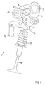
- valve train 1 according to an embodiment of the present invention in a schematic view for ease of understanding in a plan view.
- the valve drive 1 has a drive shaft 2, which is rotated by the base engine, not shown, via a drive in the form of a chain or a toothed belt or the like in rotation.
- the drive shaft 2 is shown with only one cam 3, but may be the drive shaft with cams of a multi-cylinder internal combustion engine, so that it is readily apparent that the drive shaft 2 may have a plurality of cams 3.
- the valve drive 1 shown can thus serve for the inlet control of a multi-cylinder multi-valve internal combustion engine.
- the cam 3 now follows a cam follower component or first transmission element 4 in the form of a pivoting lever.
- a rolling element 5 is rotatably arranged in the form of a roller on the pivot lever 4, so that it comes between the cam 3 and the roller 5 to a rolling operation.
- the pivot lever 4 has in the region of the bearing of the roller 5 a bore or receptacle 6, in which a spring arm 7 of a torsion spring 8 engages.
- the torsion spring 8 is received in a made of a plastic material holder 9, wherein for receiving the torsion spring 8, the holder 9 is formed in two parts and by latching the two housing halves of the holder 9, the torsion spring 8 is fixed in the holder 9.
- the thus created unit of torsion spring 8 and holder 9 can now be rotatably mounted on a bearing portion of the drive shaft or camshaft 2.
- the pivot lever 4 can be displaced by 180 degrees from the full-load basic position of the valve drive shown in FIGS. 1 and 2 of the drawing into a neutral basic position shown in FIGS. 3 to 6 by means of a rotation of an eccentric shaft 10, wherein the in FIGS. 1 and 2 of FIG Drawing shown full load position of the idle position shown in Fig. 3 and 4 in particular differs in that the point of contact between a formed on the pivot lever 4 and a control cam arranged on a second transmission element 12 roller 13 from the designated with HR Hubrampenab mustard the control curve 11 migrates to the NH designated Nullhubabexcellent the cam 11.
- the second transmission element 12 in the form of a finger lever can press on a valve stem 15 for actuation of a gas exchange valve 14 and is supported at its end 16 opposite the valve stem 15 at, for example, a hydraulically operating valve clearance compensation element 17.
- the gas exchange valve 14 is axially guided with its valve stem 15 in a valve stem guide 18 which may be pressed into a cylinder head, not shown, and is kept closed in an unopened state by means of a coil spring 19, so that the valve disc 20 against a in the cylinder head of Internal combustion engine arranged valve seat presses.
- the holder 9 is rotatably mounted at a bearing point of the drive shaft or camshaft 2, so that a rotation of the camshaft 2 does not lead to a deflection of the spring arm 7 with respect to the center axis 21 of the torsion spring 8, as long as the cam 3 rolls with its base circle on the roller 5. Since the torsion spring 8 exerts a biasing force in the basic position shown in FIG. 1, the roller 5 is pressed against the cam 3 by this pretensioning force.
- this position of the valve train 1 was achieved in that the cam 3 come into contact with the cam 5 with its cam elevation curve 22 is and thus has acted upon the pivot lever 4 in the direction of the gas exchange valve 14 out.
- the pivoting movement of the pivoting lever 4 leads to a shift of the contact point between the Hubrampenabrisk HR of the control cam 11 and the roller 13, so that the valve play compensating element 17 supporting cam followers 12 directed towards the valve stem 15 of the gas exchange valve 14 is directed downward and thus the gas exchange valve 14th in an open position presses (in Fig. 2 is the sake of simplicity, the coil spring 19th has been omitted), so that the gas exchange valve 14 is open with maximum lift height for gas exchange operation.
- the spring arm 7 of the torsion spring 8 is biased and keeps the roller 5 in contact with the cam third
- FIG. 3 of the drawing shows now the valve gear 1 in the neutral position corresponding to a basic position with the torsion spring 8 in basic position.
- the eccentric shaft 10 has been rotated by 180 degrees, which leads to a displacement of the pivot lever 4 along the control cam 11 in the designated zero NH range.
- the included between the center axis 21 and a along the center axis of the spring arm 7 reference axis 23 included angle ⁇ by the displacement of the pivot lever 4 along the control cam 11 in the area of the zero stroke section of the control cam 11 is not changed.
- the base of the torsion spring 8 corresponding biasing force is maintained, so that no change in the friction conditions in the valve train 1 has resulted from the displacement of the pivot lever 4.
- Fig. 4 of the drawings now shows a representation similar to FIG. 3 with a rotated cam, so that the gas exchange valve 14 performs a valve lift, which is sufficient to maintain the idle speed of the internal combustion engine.
- the valve lift of the gas exchange valve in the full load position is 12 mm, for example, the valve lift in the idling position may be reduced to a value of, for example, 1.5 mm.
- the biasing force generated in the deflected by the rotation of the cam 3 and tensioned position of the torsion spring 8 corresponds to the biasing force of the torsion spring 8 in the illustrated in Fig. 2 deflected position in full load operation.
- FIG. 5 of the drawings shows the valve train 1 in a position to effect selective cylinder deactivation.
- This position was realized by a further displacement of the pivot lever 4 along the zero lift curve NH of the control cam 11 by means of the application of a piston / cylinder unit 24 with, for example, pressure oil from the engine lubricating oil circuit.
- the application of the piston / cylinder unit 24 now leads to a displacement brought about by the displacement of the pivoting lever 4 due to the rotation of the eccentric shaft 10, which is additively superimposed on a further displacement of the pivoting lever 4 brought about by the piston / cylinder unit 24 such that the point of contact between the Control cam 11 and the roller 13 has been moved to the end of the zero lift NH.
- the biasing force generated by the torsion spring 8 corresponds to those of the torsion spring 8 in the tensioned state in idle position of the valve gear 1 and in tensioned state in full load position of the valve train 1 is generated.
- the biasing force of the torsion spring 8 changes in each of the cam 3 not actuated basic position or actuated by the cam 3 deflected biased position not in response to the displacement of the pivot lever 4 and thus not in response to the desired or realized valve lift ,
Landscapes
- Engineering & Computer Science (AREA)
- Mechanical Engineering (AREA)
- General Engineering & Computer Science (AREA)
- Valve Device For Special Equipments (AREA)
- Valve-Gear Or Valve Arrangements (AREA)
Applications Claiming Priority (1)
| Application Number | Priority Date | Filing Date | Title |
|---|---|---|---|
| DE102004035005A DE102004035005A1 (de) | 2004-07-20 | 2004-07-20 | Ventiltrieb einer Brennkraftmaschine |
Publications (3)
| Publication Number | Publication Date |
|---|---|
| EP1619362A2 true EP1619362A2 (fr) | 2006-01-25 |
| EP1619362A3 EP1619362A3 (fr) | 2010-01-27 |
| EP1619362B1 EP1619362B1 (fr) | 2011-04-20 |
Family
ID=35094444
Family Applications (1)
| Application Number | Title | Priority Date | Filing Date |
|---|---|---|---|
| EP05014341A Ceased EP1619362B1 (fr) | 2004-07-20 | 2005-07-01 | Distribution de moteur à combustion |
Country Status (2)
| Country | Link |
|---|---|
| EP (1) | EP1619362B1 (fr) |
| DE (2) | DE102004035005A1 (fr) |
Cited By (3)
| Publication number | Priority date | Publication date | Assignee | Title |
|---|---|---|---|---|
| DE102005040959A1 (de) * | 2005-08-30 | 2007-03-08 | Bayerische Motoren Werke Ag | Hubvariabler Ventiltrieb für eine Brennkraftmaschine |
| EP2299070A1 (fr) * | 2009-09-03 | 2011-03-23 | Otics Corporation | Mécanisme de soupape variable |
| CN102061957A (zh) * | 2009-11-12 | 2011-05-18 | 铃木株式会社 | 用于内燃机的可变阀操作系统 |
Families Citing this family (1)
| Publication number | Priority date | Publication date | Assignee | Title |
|---|---|---|---|---|
| DE102006013915A1 (de) * | 2006-03-25 | 2007-09-27 | Daimlerchrysler Ag | Hubübertragungsvorrichtung |
Citations (3)
| Publication number | Priority date | Publication date | Assignee | Title |
|---|---|---|---|---|
| EP0686756A1 (fr) | 1994-06-08 | 1995-12-13 | Bayerische Motoren Werke Aktiengesellschaft | Dispositif d'entraînement de soupape avec commande variable de l'angle d'ouverture de soupape |
| US5937809A (en) | 1997-03-20 | 1999-08-17 | General Motors Corporation | Variable valve timing mechanisms |
| US6684632B2 (en) | 2000-08-09 | 2004-02-03 | Dr. Ing. H.C.F. Porsche Ag | Arrangement and method for igniting a combustible gas mixture for the exhaust system of an internal-combustion engine and corresponding exhaust system |
Family Cites Families (6)
| Publication number | Priority date | Publication date | Assignee | Title |
|---|---|---|---|---|
| DE2363891A1 (de) * | 1973-07-13 | 1975-06-26 | Daimler Benz Ag | Ventilverstellung fuer brennkraftmaschinen |
| DE2629554A1 (de) * | 1976-07-01 | 1978-01-12 | Daimler Benz Ag | Lastregelung fuer gemischverdichtende brennkraftmaschinen mit ventilsteuerung |
| US4469056A (en) * | 1983-02-22 | 1984-09-04 | Tourtelot Jr Edward M | Dual follower variable valve timing mechanism |
| DE19913742A1 (de) * | 1999-03-26 | 2000-09-28 | Bayerische Motoren Werke Ag | Vorrichtung zur Hubverstellung eines Gaswechselventils im Zylinderkopf einer Brennkraftmaschine |
| DE10237104A1 (de) * | 2002-08-13 | 2004-02-26 | Bayerische Motoren Werke Ag | Ventiltrieb für eine Hubkolben-Brennkraftmaschine |
| US6684832B1 (en) * | 2003-04-28 | 2004-02-03 | Roberto Marcelo Codina | Oscillating camshaft controlled valve operating device |
-
2004
- 2004-07-20 DE DE102004035005A patent/DE102004035005A1/de not_active Withdrawn
-
2005
- 2005-07-01 DE DE502005011266T patent/DE502005011266D1/de active Active
- 2005-07-01 EP EP05014341A patent/EP1619362B1/fr not_active Ceased
Patent Citations (3)
| Publication number | Priority date | Publication date | Assignee | Title |
|---|---|---|---|---|
| EP0686756A1 (fr) | 1994-06-08 | 1995-12-13 | Bayerische Motoren Werke Aktiengesellschaft | Dispositif d'entraînement de soupape avec commande variable de l'angle d'ouverture de soupape |
| US5937809A (en) | 1997-03-20 | 1999-08-17 | General Motors Corporation | Variable valve timing mechanisms |
| US6684632B2 (en) | 2000-08-09 | 2004-02-03 | Dr. Ing. H.C.F. Porsche Ag | Arrangement and method for igniting a combustible gas mixture for the exhaust system of an internal-combustion engine and corresponding exhaust system |
Cited By (4)
| Publication number | Priority date | Publication date | Assignee | Title |
|---|---|---|---|---|
| DE102005040959A1 (de) * | 2005-08-30 | 2007-03-08 | Bayerische Motoren Werke Ag | Hubvariabler Ventiltrieb für eine Brennkraftmaschine |
| EP2299070A1 (fr) * | 2009-09-03 | 2011-03-23 | Otics Corporation | Mécanisme de soupape variable |
| CN102061957A (zh) * | 2009-11-12 | 2011-05-18 | 铃木株式会社 | 用于内燃机的可变阀操作系统 |
| CN102061957B (zh) * | 2009-11-12 | 2013-05-08 | 铃木株式会社 | 用于内燃机的可变阀操作系统 |
Also Published As
| Publication number | Publication date |
|---|---|
| DE102004035005A1 (de) | 2006-02-16 |
| EP1619362A3 (fr) | 2010-01-27 |
| EP1619362B1 (fr) | 2011-04-20 |
| DE502005011266D1 (de) | 2011-06-01 |
Similar Documents
| Publication | Publication Date | Title |
|---|---|---|
| EP0659232B1 (fr) | Procede et dispositif de commande variable d'une soupape d'un moteur a combustion interne | |
| DE19960742B4 (de) | Variabler Ventiltrieb, vorzugsweise für Verbrennungsmotoren | |
| DE10006018B4 (de) | Variabler Ventiltrieb zur Laststeuerung einer fremdgezündeten Brennkraftmaschine | |
| DE3786587T2 (de) | Ventilantrieb fuer eine brennkraftmaschine. | |
| DE69708757T2 (de) | Hydraulischer Ventilstössel | |
| WO2009152927A9 (fr) | Distribution pour les soupapes d'échange de gaz d'un moteur à combustion interne avec des supports de came doublement soutenus | |
| EP0627043B1 (fr) | Mecanisme d'actionnement des soupapes pour un moteur a combustion interne | |
| DE19908286A1 (de) | Variable Ventilsteuerung für Brennkraftmaschinen | |
| DE102007010155A1 (de) | Ventiltrieb einer Brennkraftmaschine mit dreistufigen Nockenprofilgruppen | |
| WO2005075797A1 (fr) | Galet suiveur levier schlepphebel destine a une inversion de course | |
| EP0521412A1 (fr) | Moteur à combustion interne avec culbuteur pour la commande de soupape | |
| EP1619362B1 (fr) | Distribution de moteur à combustion | |
| DE102008027649A1 (de) | Ventilbetrieb für eine Brennkraftmaschine | |
| EP1205643A1 (fr) | Dispositif d'actionnement de soupapes de moteur à combustion interne | |
| DE4411182B4 (de) | Schaltbare Ventilsteuerung für Brennkraftmaschinen | |
| EP3173593B1 (fr) | Commande de soupape variable comprenant un culbuteur | |
| EP1022443B1 (fr) | Dispositif de commande variable pour soupape de moteur a combustion interne | |
| DE10312959A1 (de) | Vorrichtung zur variablen Betätigung der Gaswechselventile von Verbrennungsmotoren und Verfahren zum Betreiben einer derartigen Vorrichtung | |
| DE4321308C1 (de) | Ventilbetätigungsvorrichtung für eine Brennkraftmaschine | |
| DE4230809C2 (de) | Ventilsteuerung für Brennkraftmaschinen | |
| DE4243169C1 (de) | Variable Ventilsteuerungseinrichtung | |
| DE102004040652A1 (de) | Vollvariabler fünfgliedriger Ventiltrieb einer Brennkraftmaschine | |
| EP1590554B1 (fr) | Entrainement mecanique de soupape entierement variable destine a moteur a combustion interne a piston alternatif a equilibre de jeu de soupapes reglable | |
| WO2005026503A2 (fr) | Commande a soupapes de levage entierement variable de moteur a combustion interne | |
| AT514535B1 (de) | Ventilbetätigungseinrichtung |
Legal Events
| Date | Code | Title | Description |
|---|---|---|---|
| PUAI | Public reference made under article 153(3) epc to a published international application that has entered the european phase |
Free format text: ORIGINAL CODE: 0009012 |
|
| AK | Designated contracting states |
Kind code of ref document: A2 Designated state(s): AT BE BG CH CY CZ DE DK EE ES FI FR GB GR HU IE IS IT LI LT LU LV MC NL PL PT RO SE SI SK TR |
|
| AX | Request for extension of the european patent |
Extension state: AL BA HR MK YU |
|
| PUAL | Search report despatched |
Free format text: ORIGINAL CODE: 0009013 |
|
| AK | Designated contracting states |
Kind code of ref document: A3 Designated state(s): AT BE BG CH CY CZ DE DK EE ES FI FR GB GR HU IE IS IT LI LT LU LV MC NL PL PT RO SE SI SK TR |
|
| AX | Request for extension of the european patent |
Extension state: AL BA HR MK YU |
|
| 17P | Request for examination filed |
Effective date: 20100211 |
|
| 17Q | First examination report despatched |
Effective date: 20100319 |
|
| AKX | Designation fees paid |
Designated state(s): DE FR GB IT |
|
| GRAP | Despatch of communication of intention to grant a patent |
Free format text: ORIGINAL CODE: EPIDOSNIGR1 |
|
| GRAS | Grant fee paid |
Free format text: ORIGINAL CODE: EPIDOSNIGR3 |
|
| GRAA | (expected) grant |
Free format text: ORIGINAL CODE: 0009210 |
|
| AK | Designated contracting states |
Kind code of ref document: B1 Designated state(s): DE FR GB IT |
|
| REG | Reference to a national code |
Ref country code: GB Ref legal event code: FG4D Free format text: NOT ENGLISH |
|
| REF | Corresponds to: |
Ref document number: 502005011266 Country of ref document: DE Date of ref document: 20110601 Kind code of ref document: P |
|
| REG | Reference to a national code |
Ref country code: DE Ref legal event code: R096 Ref document number: 502005011266 Country of ref document: DE Effective date: 20110601 |
|
| PLBE | No opposition filed within time limit |
Free format text: ORIGINAL CODE: 0009261 |
|
| STAA | Information on the status of an ep patent application or granted ep patent |
Free format text: STATUS: NO OPPOSITION FILED WITHIN TIME LIMIT |
|
| 26N | No opposition filed |
Effective date: 20120123 |
|
| REG | Reference to a national code |
Ref country code: DE Ref legal event code: R097 Ref document number: 502005011266 Country of ref document: DE Effective date: 20120123 |
|
| REG | Reference to a national code |
Ref country code: FR Ref legal event code: PLFP Year of fee payment: 12 |
|
| REG | Reference to a national code |
Ref country code: FR Ref legal event code: PLFP Year of fee payment: 13 |
|
| PGFP | Annual fee paid to national office [announced via postgrant information from national office to epo] |
Ref country code: DE Payment date: 20170712 Year of fee payment: 13 Ref country code: GB Payment date: 20170724 Year of fee payment: 13 Ref country code: FR Payment date: 20170720 Year of fee payment: 13 Ref country code: IT Payment date: 20170721 Year of fee payment: 13 |
|
| REG | Reference to a national code |
Ref country code: DE Ref legal event code: R119 Ref document number: 502005011266 Country of ref document: DE |
|
| GBPC | Gb: european patent ceased through non-payment of renewal fee |
Effective date: 20180701 |
|
| PG25 | Lapsed in a contracting state [announced via postgrant information from national office to epo] |
Ref country code: FR Free format text: LAPSE BECAUSE OF NON-PAYMENT OF DUE FEES Effective date: 20180731 Ref country code: GB Free format text: LAPSE BECAUSE OF NON-PAYMENT OF DUE FEES Effective date: 20180701 Ref country code: DE Free format text: LAPSE BECAUSE OF NON-PAYMENT OF DUE FEES Effective date: 20190201 |
|
| PG25 | Lapsed in a contracting state [announced via postgrant information from national office to epo] |
Ref country code: IT Free format text: LAPSE BECAUSE OF NON-PAYMENT OF DUE FEES Effective date: 20180701 |