JP4039383B2 - Internal combustion engine using hydrogen - Google Patents
Internal combustion engine using hydrogen Download PDFInfo
- Publication number
- JP4039383B2 JP4039383B2 JP2004116609A JP2004116609A JP4039383B2 JP 4039383 B2 JP4039383 B2 JP 4039383B2 JP 2004116609 A JP2004116609 A JP 2004116609A JP 2004116609 A JP2004116609 A JP 2004116609A JP 4039383 B2 JP4039383 B2 JP 4039383B2
- Authority
- JP
- Japan
- Prior art keywords
- gasoline
- hydrogen
- fuel
- rich gas
- dehydrogenated
- Prior art date
- Legal status (The legal status is an assumption and is not a legal conclusion. Google has not performed a legal analysis and makes no representation as to the accuracy of the status listed.)
- Expired - Fee Related
Links
Images


Classifications
-
- C—CHEMISTRY; METALLURGY
- C01—INORGANIC CHEMISTRY
- C01B—NON-METALLIC ELEMENTS; COMPOUNDS THEREOF; METALLOIDS OR COMPOUNDS THEREOF NOT COVERED BY SUBCLASS C01C
- C01B3/00—Hydrogen; Gaseous mixtures containing hydrogen; Separation of hydrogen from mixtures containing it; Purification of hydrogen
- C01B3/02—Production of hydrogen or of gaseous mixtures containing a substantial proportion of hydrogen
- C01B3/22—Production of hydrogen or of gaseous mixtures containing a substantial proportion of hydrogen by decomposition of gaseous or liquid organic compounds
- C01B3/24—Production of hydrogen or of gaseous mixtures containing a substantial proportion of hydrogen by decomposition of gaseous or liquid organic compounds of hydrocarbons
- C01B3/26—Production of hydrogen or of gaseous mixtures containing a substantial proportion of hydrogen by decomposition of gaseous or liquid organic compounds of hydrocarbons using catalysts
-
- F—MECHANICAL ENGINEERING; LIGHTING; HEATING; WEAPONS; BLASTING
- F02—COMBUSTION ENGINES; HOT-GAS OR COMBUSTION-PRODUCT ENGINE PLANTS
- F02M—SUPPLYING COMBUSTION ENGINES IN GENERAL WITH COMBUSTIBLE MIXTURES OR CONSTITUENTS THEREOF
- F02M21/00—Apparatus for supplying engines with non-liquid fuels, e.g. gaseous fuels stored in liquid form
- F02M21/02—Apparatus for supplying engines with non-liquid fuels, e.g. gaseous fuels stored in liquid form for gaseous fuels
-
- F—MECHANICAL ENGINEERING; LIGHTING; HEATING; WEAPONS; BLASTING
- F02—COMBUSTION ENGINES; HOT-GAS OR COMBUSTION-PRODUCT ENGINE PLANTS
- F02M—SUPPLYING COMBUSTION ENGINES IN GENERAL WITH COMBUSTIBLE MIXTURES OR CONSTITUENTS THEREOF
- F02M25/00—Engine-pertinent apparatus for adding non-fuel substances or small quantities of secondary fuel to combustion-air, main fuel or fuel-air mixture
- F02M25/10—Engine-pertinent apparatus for adding non-fuel substances or small quantities of secondary fuel to combustion-air, main fuel or fuel-air mixture adding acetylene, non-waterborne hydrogen, non-airborne oxygen, or ozone
-
- F—MECHANICAL ENGINEERING; LIGHTING; HEATING; WEAPONS; BLASTING
- F02—COMBUSTION ENGINES; HOT-GAS OR COMBUSTION-PRODUCT ENGINE PLANTS
- F02M—SUPPLYING COMBUSTION ENGINES IN GENERAL WITH COMBUSTIBLE MIXTURES OR CONSTITUENTS THEREOF
- F02M27/00—Apparatus for treating combustion-air, fuel, or fuel-air mixture, by catalysts, electric means, magnetism, rays, sound waves, or the like
- F02M27/02—Apparatus for treating combustion-air, fuel, or fuel-air mixture, by catalysts, electric means, magnetism, rays, sound waves, or the like by catalysts
-
- C—CHEMISTRY; METALLURGY
- C01—INORGANIC CHEMISTRY
- C01B—NON-METALLIC ELEMENTS; COMPOUNDS THEREOF; METALLOIDS OR COMPOUNDS THEREOF NOT COVERED BY SUBCLASS C01C
- C01B2203/00—Integrated processes for the production of hydrogen or synthesis gas
- C01B2203/02—Processes for making hydrogen or synthesis gas
- C01B2203/0266—Processes for making hydrogen or synthesis gas containing a decomposition step
- C01B2203/0277—Processes for making hydrogen or synthesis gas containing a decomposition step containing a catalytic decomposition step
-
- F—MECHANICAL ENGINEERING; LIGHTING; HEATING; WEAPONS; BLASTING
- F02—COMBUSTION ENGINES; HOT-GAS OR COMBUSTION-PRODUCT ENGINE PLANTS
- F02M—SUPPLYING COMBUSTION ENGINES IN GENERAL WITH COMBUSTIBLE MIXTURES OR CONSTITUENTS THEREOF
- F02M25/00—Engine-pertinent apparatus for adding non-fuel substances or small quantities of secondary fuel to combustion-air, main fuel or fuel-air mixture
- F02M25/10—Engine-pertinent apparatus for adding non-fuel substances or small quantities of secondary fuel to combustion-air, main fuel or fuel-air mixture adding acetylene, non-waterborne hydrogen, non-airborne oxygen, or ozone
- F02M25/12—Engine-pertinent apparatus for adding non-fuel substances or small quantities of secondary fuel to combustion-air, main fuel or fuel-air mixture adding acetylene, non-waterborne hydrogen, non-airborne oxygen, or ozone the apparatus having means for generating such gases
-
- Y—GENERAL TAGGING OF NEW TECHNOLOGICAL DEVELOPMENTS; GENERAL TAGGING OF CROSS-SECTIONAL TECHNOLOGIES SPANNING OVER SEVERAL SECTIONS OF THE IPC; TECHNICAL SUBJECTS COVERED BY FORMER USPC CROSS-REFERENCE ART COLLECTIONS [XRACs] AND DIGESTS
- Y02—TECHNOLOGIES OR APPLICATIONS FOR MITIGATION OR ADAPTATION AGAINST CLIMATE CHANGE
- Y02T—CLIMATE CHANGE MITIGATION TECHNOLOGIES RELATED TO TRANSPORTATION
- Y02T10/00—Road transport of goods or passengers
- Y02T10/10—Internal combustion engine [ICE] based vehicles
- Y02T10/12—Improving ICE efficiencies
Description
本発明は、水素利用内燃機関に係り、特に、水素化燃料、車両内で生成した水素リッチガス及び脱水素生成物を燃料として利用することのできる水素利用内燃機関に関する。 The present invention relates to a hydrogen-utilizing internal combustion engine, and more particularly, to a hydrogen-utilizing internal combustion engine that can use hydrogenated fuel, a hydrogen-rich gas generated in a vehicle, and a dehydrogenated product as fuel.
自動車を駆動するための動力源として、従来からガソリンを燃料とするガソリンエンジンが広く利用されている。ガソリンエンジンは、一般に主燃料であるガソリンに空気を混合した混合気体を燃焼させて発動するものであるが、近年この混合気体にさらに水素を添加する技術の実用化が検討されている。 As a power source for driving automobiles, gasoline engines using gasoline as fuel have been widely used. In general, a gasoline engine is started by burning a mixed gas in which air is mixed with gasoline, which is a main fuel, and in recent years, a technique for adding hydrogen to the mixed gas has been studied.
また、自動車用燃料としては、今後ガソリンエシジンや、ディーゼルエンジン、水素エンジンをはじめとする内燃機関のみならず、電気自動車などに搭載される燃料電池等のエンジン以外の水素使用装置においても水素の利用が増加するものと推定される。 As fuel for automobiles, hydrogen will be used not only in gasoline ecidine, diesel engines, hydrogen engines, and other internal combustion engines, but also in hydrogen-using devices other than engines such as fuel cells installed in electric vehicles. It is estimated that usage will increase.
ところが、水素の供給方制に関する技術は未だ確立されていないのが現況であり、内燃機関や燃料電池等に水素を供給しようとする場合には、車両に水素または水素を生成するための原燃料を搭載する必要がある。すなわち、水素を搭載する場合には、水素リッチガスを圧縮して高圧に若しくは液状にして充填したボンベ(高圧タンクや液体水素タンクなど)、または水素を吸蔵する水素吸蔵合金や水素吸着材料によって搭載し、原燃料を搭載する場合には、原燃料としてのメタノールまたはガソリン等の炭化水素とこの原燃料を水蒸気改質して水素リッチガスを生成する水素生成装置とが搭載される。 However, the current technology for supplying hydrogen is not yet established, and when hydrogen is to be supplied to an internal combustion engine, a fuel cell, etc., hydrogen or raw fuel for generating hydrogen in a vehicle is used. Need to be installed. In other words, when hydrogen is loaded, it is loaded with a cylinder (such as a high-pressure tank or liquid hydrogen tank) filled with hydrogen-rich gas compressed to high pressure or liquid, or a hydrogen storage alloy or hydrogen adsorbing material that stores hydrogen. When the raw fuel is mounted, a hydrocarbon such as methanol or gasoline as the raw fuel and a hydrogen generator for generating a hydrogen rich gas by steam reforming the raw fuel are mounted.
しかしながら、車両に水素自体を搭載する場合、高圧タンクに圧縮した状態で搭載すると、高圧タンクは大きいわりに壁厚が厚く内容積を大きくできないために水素充填量が少ない。液体水素として搭載する場合は、気化ロスがあるほか、液化に多大なエネルギーを要するため総合的なエネルギー効率の点で望ましくない。また、水素吸蔵合金や水素吸着材料では、必要とされる水素貯蔵密度が不充分であり、また水素の吸蔵や吸着等を制御するのが非常に困難である。また更に、水素を高圧化、液化したり、吸蔵するのに設備を別途整備する必要もある。 However, when hydrogen is mounted on a vehicle, if it is mounted in a compressed state in a high-pressure tank, the high-pressure tank is large but the wall thickness is large and the internal volume cannot be increased, so that the amount of hydrogen filling is small. In the case of mounting as liquid hydrogen, there is a vaporization loss, and it requires a lot of energy for liquefaction, which is not desirable in terms of overall energy efficiency. Also, hydrogen storage alloys and hydrogen adsorbing materials have insufficient hydrogen storage density, and it is very difficult to control hydrogen storage and adsorption. Furthermore, it is also necessary to separately prepare equipment for increasing the pressure, liquefying, and storing hydrogen.
一方、原燃料を搭載する場合は、水素を搭載する場合に比して1回の燃料補給で走行可能な距離が長いという利点を有しており、炭化水素系の原燃料では水素リッチガスとの比較において輸送等の取り扱いが容易であるという利点も有している。また、水素は燃焼しても空中の酸素と結合して水となるだけで公害の心配がない。 On the other hand, when the raw fuel is loaded, there is an advantage that the distance that can be traveled by one refueling is longer than when the hydrogen is loaded. In comparison, there is also an advantage that handling such as transportation is easy. Also, even if hydrogen burns, it only combines with oxygen in the air to become water, so there is no concern about pollution.
例えば炭化水素系物質の1つであるデカリン(デカヒドロナフタレン)は、常温では殆ど蒸気圧がゼロ(沸点が200℃近傍)で取り扱いし易いことから、原燃料としての使用の可能性が期待されている。 For example, decalin (decahydronaphthalene), which is one of the hydrocarbon-based substances, is easy to handle at room temperature because the vapor pressure is almost zero (boiling point is around 200 ° C), so it can be used as a raw fuel. ing.
デカリンの脱水素化方法としては、デカリンをコバルト、ロジウム、イリジウム、鉄、テルニウム、ニッケル、および白金の中から選ばれる少なくとも1種の遷移金属を含有する遷移金属錯体の存在下で光照射し、デカリンから水素を離脱させる方法が知られている(例えば、特許文献1参照)。また、有機リン化合物のロジウム錯体の存在下、または有機リン化合物とロジウム化合物との存在下に、デカリンに光照射することによりデカリンから水素を製造する方法が知られている(例えば、特許文献2参照)。デカリンの脱水素反応は以下のように行なわれる。 Decalin is dehydrogenated by irradiating decalin in the presence of a transition metal complex containing at least one transition metal selected from cobalt, rhodium, iridium, iron, ternium, nickel, and platinum, A method for releasing hydrogen from decalin is known (for example, see Patent Document 1). In addition, a method for producing hydrogen from decalin by irradiating light to decalin in the presence of a rhodium complex of an organophosphorus compound or in the presence of an organophosphorus compound and a rhodium compound is known (for example, Patent Document 2). reference). Decalin dehydrogenation is carried out as follows.
C10H18(デカリン)→C10H8(ナフタレン)+5H2(水素) C 10 H 18 (decalin) → C 10 H 8 (naphthalene) + 5H 2 (hydrogen)
また、原燃料として、デカリンやシクロヘキサンなどの有機ハイドライドを用いた水素燃料供給システムが開示されているものがある(例えば、特許文献3,4参照)。
従って、本発明の第1の目的は、上記有機ハイドライドや、ガソリン、軽油等を水素化したもの(以下、「水素化燃料という」)を、直接または、分解して、ガソリンエンジンやディーゼルエンジン、水素エンジンなどの内燃機関に供するシステムを提供することにある。
また、本発明の第2の目的は、有機ハイドライドを含む水素化ガソリンから、水素リッチガスおよび脱水素化ガソリンを生成して、それらの中で最適な燃料を内燃機関に
Accordingly, the first object of the present invention is to directly or decompose the above-mentioned organic hydride, hydrogenated gasoline, light oil or the like (hereinafter referred to as “hydrogenated fuel”) to produce a gasoline engine, diesel engine, The object is to provide a system for use in an internal combustion engine such as a hydrogen engine.
The second object of the present invention is to produce hydrogen rich gas and dehydrogenated gasoline from hydrogenated gasoline containing organic hydride, and use the optimal fuel among them as an internal combustion engine.
<水素化燃料>
本発明の水素利用内燃機関には、水素化燃料を用いる。
本発明において、水素化燃料は、有機ハイドライド並びに軽油・ガソリン等の内燃機関燃料に水素を付加したものから選ばれる1種、又は2種以上の混合物をいう。
<Hydrogenated fuel>
Hydrogenated fuel is used in the hydrogen-utilizing internal combustion engine of the present invention.
In the present invention, the hydrogenated fuel refers to one or a mixture of two or more selected from organic hydrides and fuels of internal combustion engines such as light oil and gasoline added with hydrogen.
ここで、有機ハイドライドとは、脱水素反応により水素を発生し得る飽和炭化水素を含む燃料を意味し、非環式や環式の炭化水素、および非環式や環式の含酸素炭化水素などがこれに該当する。非環式の炭化水素には、例えば、n-ヘキサンやiso-オクタンが含まれる。また、環式の炭化水素には、例えば、シクロヘキサン、メチルシクロヘキサンなどの単環式化合物、デカリンなどの2環式化合物が含まれる。更に、含酸素炭化水素には、シクロヘキサノールやシクロヘキサンメタノールなどのアルコール類や、メチル-t-ブチルエーテルなどのエーテル類などが含まれる。 Here, the organic hydride means a fuel containing a saturated hydrocarbon that can generate hydrogen by a dehydrogenation reaction, such as an acyclic or cyclic hydrocarbon, and an acyclic or cyclic oxygen-containing hydrocarbon. Corresponds to this. Acyclic hydrocarbons include, for example, n-hexane and iso-octane. The cyclic hydrocarbon includes, for example, monocyclic compounds such as cyclohexane and methylcyclohexane, and bicyclic compounds such as decalin. Further, the oxygen-containing hydrocarbon includes alcohols such as cyclohexanol and cyclohexane methanol, ethers such as methyl-t-butyl ether, and the like.
上記の水素化燃料から脱水素されて得られた脱水素生成物とは、上記の有機ハイドライドを脱水素反応して水素を放出した後の反応生成物であり、例えば、シクロヘキサンの場合には、水素と共に主として生成されるベンゼンが相当する。 The dehydrogenation product obtained by dehydrogenating the hydrogenated fuel is a reaction product after dehydrogenating the organic hydride to release hydrogen. For example, in the case of cyclohexane, This corresponds to benzene produced mainly with hydrogen.
前記有機ハイドライドを脱水素反応させると、水素リッチガスと共に、水素の放出により不飽和結合を持つ環状不飽和物が反応生成物として生成される。例えば、シクロヘキサンからなる燃料またはシクロヘキサンを主成分とする燃料を用いた場合には、シクロヘキサンの脱水素反応により、水素リッチガスと共に環状不飽和物としてベンゼンが生成される。 When the organic hydride is subjected to a dehydrogenation reaction, a cyclic unsaturated compound having an unsaturated bond is generated as a reaction product along with a hydrogen-rich gas by releasing hydrogen. For example, when a fuel composed of cyclohexane or a fuel containing cyclohexane as a main component is used, benzene is generated as a cyclic unsaturated substance together with a hydrogen-rich gas by a dehydrogenation reaction of cyclohexane.
一方、水素化燃料は、石油精製プロセスにおいて、上記のような有機ハイドライドを多く含む留分を改質あるいはブレンド調製することで生成することができる。また、軽油・ガソリン等の内燃機関燃料は環式、非環式の不飽和炭化水素を含有しているため、それらに水素を付加することによっても水素化燃料は生成することができる。
水素付加の方法は特に限定されないが、加熱された触媒上で不飽和物等と水素リッチガスを反応させる方法が挙げられる(特開2000−255503号等)。
そして、該環状不飽和物であるベンゼンを水素添加により水素化皮応させたときには、ベンゼンの水素化物であるシクロヘキサンが生成(再生)される。
水素化燃料は、水素化燃料貯留部に供給される。水素化燃料貯留部は、水素化燃料単独のタンクでもよいし、後述する水素分離後の脱水素生成物との共有タンクであってもよい。
本発明においては、水素化燃料貯留部から内燃機関に直接水素化燃料を供給することができ、水素化燃料を直接内燃機関の燃料とすることができる。
On the other hand, the hydrogenated fuel can be produced by reforming or blending a fraction containing a large amount of organic hydride as described above in an oil refining process. Further, since internal combustion engine fuels such as light oil and gasoline contain cyclic and acyclic unsaturated hydrocarbons, hydrogenated fuel can also be generated by adding hydrogen to them.
The method of hydrogenation is not particularly limited, and examples thereof include a method of reacting an unsaturated substance and the like with a hydrogen rich gas on a heated catalyst (JP 2000-255503 A).
When the cyclic unsaturated benzene is hydrogenated by hydrogenation, cyclohexane, which is a benzene hydride, is generated (regenerated).
The hydrogenated fuel is supplied to the hydrogenated fuel storage unit. The hydrogenated fuel storage unit may be a tank of hydrogenated fuel alone or a shared tank with a dehydrogenated product after hydrogen separation described later.
In the present invention, the hydrogenated fuel can be supplied directly from the hydrogenated fuel reservoir to the internal combustion engine, and the hydrogenated fuel can be directly used as the fuel for the internal combustion engine.
<反応手段>
一方、水素化燃料は、加熱可能に配置された触媒を備え、該触媒上で脱水素反応させる反応手段へと導くこともできる。
<Reaction means>
On the other hand, the hydrogenated fuel can be led to a reaction means including a catalyst arranged so as to be heatable and performing a dehydrogenation reaction on the catalyst.
このような反応手段は、特に限定されないが、加熱可能なハニカム担体の各セル内に金属触媒層を設け、かつ該触媒に水素化燃料を供給する燃料供給装置を有するものが好ましいものとして挙げられる。 Such a reaction means is not particularly limited, but a preferable example is one having a metal catalyst layer in each cell of a heatable honeycomb carrier and having a fuel supply device for supplying hydrogenated fuel to the catalyst. .
ここで用いるハニカム担体は、ステンレス等の金属、セラミック、カーボン等の材質のものが挙げられ、セル数は、45〜310セル/cm2で、水素化燃料入口直径と奥行長さの比(直径/長さ)が0.1〜0.5である触媒担持用ハニカム担体が好ましい。また、セル1個の断面形状は、特に限定されず、四角、六角、三角等が挙げられる。 Examples of the honeycomb carrier used here include metals such as stainless steel, ceramics, carbon, and the like. The number of cells is 45 to 310 cells / cm 2 , and the ratio of the hydrogenated fuel inlet diameter to the depth length (diameter). A catalyst supporting honeycomb carrier having a / length) of 0.1 to 0.5 is preferable. Moreover, the cross-sectional shape of one cell is not particularly limited, and examples thereof include a square, a hexagon, and a triangle.
金属触媒層は、白金、パラジウム、ロジウム、レニウム、ルテニウム及ひニッケル等から選ばれる1種又は2種以上の塩又は錯体を含有してなるが、このような触媒とハニカム担体の間にはコート層を設けることが好ましい。コ一卜層は、アルミナ、セリア、ジルコニア、カーボン、ゼオライト、セピオライト及びモルデナイト等から選ばれる1種又は2種以上とバインダー(アルミナ等を構成する金属元素の水酸化塩又は酸化塩)と水を混練して塗布等することにより、設けることができる。 The metal catalyst layer contains one or more salts or complexes selected from platinum, palladium, rhodium, rhenium, ruthenium, nickel, etc., and there is a coating between such a catalyst and the honeycomb carrier. It is preferable to provide a layer. The first layer is composed of one or more selected from alumina, ceria, zirconia, carbon, zeolite, sepiolite, mordenite, etc., a binder (a hydroxide or oxide salt of a metal element constituting alumina) and water. It can be provided by kneading and coating.
金属触媒の使用量は、適宜決定すればよいが、ハニカム担体容量1リットル当たり、1g〜20gとすることが好ましい。 The amount of the metal catalyst used may be determined as appropriate, but is preferably 1 to 20 g per liter of honeycomb carrier capacity.
触媒の加熱手段は、特に限定されず、内燃機関の発熱を利用してもよいし、排出ガスの熱を利用してもよいし、独自した加熱手段により加熱してもよいが、内燃機関からの排出ガスの熱を利用することが、エネルギーの有効利用の観点から好ましい。 The heating means of the catalyst is not particularly limited, and the heat generated by the internal combustion engine may be used, the heat of the exhaust gas may be used, or the heating may be performed by a unique heating means. It is preferable to use the heat of the exhaust gas from the viewpoint of effective use of energy.
例えば、触媒が排出ガスを排気する排気管を取り巻いて形成されている場合、触媒は排気熱が排気管を熱伝達して加熱される。これにより、内燃機関の廃熱である排気熱、すなわち熱エネルギーの有効利用が可能となるが、例えばガソリンエンジンなど、内燃機関から排出される排出ガスは概ね400℃以上にも達するため、排気熱の利用によると脱水素反応を担う触媒温度を脱水素化に必要な250℃以上に安定的に保持することができる。その結果、別途熱源を設ける必要がなく、装置全体の小型・軽量化が図れると共に、内燃系統におけるエネルギー利用効率を高めることができる。しかも、排気管内において排気抵抗となるものが加わることもないため、内燃機関の性能低下を来すこともない。また、一般に排気管は金属からなるため熱伝導性が高く、排出ガスの排気熱を効果的に触媒に伝達することができる。 For example, when the catalyst is formed surrounding an exhaust pipe that exhausts exhaust gas, the catalyst is heated by exhaust heat transferring through the exhaust pipe. As a result, exhaust heat that is waste heat of the internal combustion engine, that is, thermal energy can be effectively used. However, exhaust gas discharged from the internal combustion engine, such as a gasoline engine, reaches approximately 400 ° C. or more, and therefore exhaust heat By using this, the catalyst temperature responsible for the dehydrogenation reaction can be stably maintained at 250 ° C. or higher necessary for dehydrogenation. As a result, it is not necessary to provide a separate heat source, the entire apparatus can be reduced in size and weight, and the energy utilization efficiency in the internal combustion system can be increased. In addition, since there is no added exhaust resistance in the exhaust pipe, the performance of the internal combustion engine does not deteriorate. Further, since the exhaust pipe is generally made of metal, the heat conductivity is high, and the exhaust heat of the exhaust gas can be effectively transmitted to the catalyst.
燃料供給装置は、解媒に水素化燃料を供給できる位置に設けられ、セル入口に対して水素化燃料を広角に噴霧等して供給可能なように構成することができる。例えば、インジェクタ(噴射装置)などが好適であり、これは制御用のドライバを接続して個々の供給装置ごとに噴射量を適宜コントロールすることができる。また、単一の反応手段に複数の燃料供給装置を設けることができ、好ましくは触媒上に水素化燃料の液膜状態が形成されるように供給される。 The fuel supply device is provided at a position where hydrogenated fuel can be supplied to the solvent, and can be configured such that the hydrogenated fuel can be supplied to the cell inlet by spraying at a wide angle. For example, an injector (injection device) or the like is suitable, and a control driver can be connected to appropriately control the injection amount for each supply device. In addition, a plurality of fuel supply devices can be provided in a single reaction means, and the fuel is preferably supplied so that a liquid film state of hydrogenated fuel is formed on the catalyst.
反応手段には、反応手段と連通し、かつ反応手段における脱水素反応によって生じた混合気体が通過する流路を、排気管に沿うようにして更に設けることができる。これにより、反応手段で生じた水素リッチガスおよび脱水素生成物を含む混合ガス(水素リッチガス)を高温状態のまま、すなわち脱水素生成物を気体状態のままにでき、容易に管内を挿通させることができる。 The reaction means can further be provided with a flow path that communicates with the reaction means and through which the mixed gas generated by the dehydrogenation reaction in the reaction means passes along the exhaust pipe. Thereby, the mixed gas (hydrogen-rich gas) containing the hydrogen-rich gas and the dehydrogenation product generated in the reaction means can be kept in a high temperature state, that is, the dehydrogenation product can be kept in a gas state, and can easily be inserted into the pipe. it can.
内燃機関の排出ガスを排気する排気管は、通常単一の管で構成できるが、単一の管から複数に分岐させて設けることもできる。この場合、分岐された各々の排気管ごとに反応手段を備えることが可能で、車両内に複数の反応手段を設けることができる。その結果、供給可能な水素量を増加することができる。 The exhaust pipe for exhausting the exhaust gas of the internal combustion engine can usually be constituted by a single pipe, but can also be provided by branching from a single pipe into a plurality of branches. In this case, reaction means can be provided for each branched exhaust pipe, and a plurality of reaction means can be provided in the vehicle. As a result, the amount of hydrogen that can be supplied can be increased.
<分離手段>
分離手段は、反応手段において、水素化燃料の脱水素反応で生じた水素リッチガスと脱水素生成物との混合気体から水素リッチガスを分離するものである。
<Separation means>
The separation means separates the hydrogen rich gas from the mixed gas of the hydrogen rich gas and the dehydrogenated product generated by the dehydrogenation reaction of the hydrogenated fuel in the reaction means.
分離手段としては、該混合気体を熱交換や断熱膨張などで冷却し、脱水素生成物を重カや遠心力で分離する方法や、該混合気体を高分子やPd薄膜等の水素透過膜で分離する方法や、該混合気体を活性炭などの有機物吸着剤に通気し、脱水素生成物を分離する方法などが挙げられる。 As the separation means, the mixed gas is cooled by heat exchange or adiabatic expansion, and the dehydrogenated product is separated by heavy power or centrifugal force, or the mixed gas is separated by a hydrogen permeable membrane such as a polymer or a Pd thin film. Examples of the separation method include a method of separating the dehydrogenated product by passing the mixed gas through an organic adsorbent such as activated carbon.
<脱水素生成物>
水素リッチガスと分離された脱水素生成物は、脱水素生成物貯留部に貯留される。
<Dehydrogenation product>
The dehydrogenation product separated from the hydrogen rich gas is stored in the dehydrogenation product storage unit.
脱水素生成物貯留部は、単独でタンクを設ける代わりに、水素化燃料を貯留する水素化燃料貯留部とを含む複室貯留タンクとすることが好ましい。この場合、水素化燃料貯留部と水素リッチガスを分離した脱水素生成物貯留部とのそれぞれが伸縮性樹脂材料を用いたものとすることが好ましい。このようにすれば、単一のタンクに統括することができ、車両などの限られた場所でも設置が可能となり、軽量化も図れる。また、水素リッチガスが除去された脱水素生成物が貯留されるので、水素リッチガスを排出する排出口を設ける必要がない。 The dehydrogenation product storage section is preferably a multi-chamber storage tank including a hydrogenated fuel storage section for storing hydrogenated fuel, instead of providing a tank alone. In this case, it is preferable that each of the hydrogenated fuel storage part and the dehydrogenation product storage part from which the hydrogen-rich gas is separated uses a stretchable resin material. In this way, it can be integrated into a single tank, can be installed in a limited place such as a vehicle, and can be reduced in weight. Moreover, since the dehydrogenation product from which the hydrogen-rich gas has been removed is stored, there is no need to provide a discharge port for discharging the hydrogen-rich gas.
脱水素生成物は、内燃機関に送りこめば、従来のガソリン等の燃料と同様に燃料として使用できる。また、脱水素生成物を回収して、水素化を行ない、水素化燃料として再び用いることもできる。 The dehydrogenation product can be used as a fuel in the same manner as a conventional fuel such as gasoline if it is sent to an internal combustion engine. In addition, the dehydrogenated product can be recovered, hydrogenated, and used again as a hydrogenated fuel.
<水素リッチガス>
分離手段で分離された水素リッチガスは、内燃機関に供給することができる。また、水素化燃料又は脱水素生成物とともに内燃機関に供給してもよい。このため、内燃機関の吸気系、燃焼室および排気系の少なくとも一つに供給する水素供給手段を設けることができる。水素供給手段は、場合により適宜選択でき、例えば、インジェクタ(噴射装置)などが好適である。
<Hydrogen rich gas>
The hydrogen rich gas separated by the separation means can be supplied to the internal combustion engine. Moreover, you may supply to an internal combustion engine with hydrogenated fuel or a dehydrogenation product. For this reason, hydrogen supply means for supplying at least one of the intake system, the combustion chamber, and the exhaust system of the internal combustion engine can be provided. The hydrogen supply means can be appropriately selected depending on the case. For example, an injector (injection device) is suitable.
上記の目的を達成するために、第1の発明は、水素利用内燃機関であって、
有機ハイドライドを含む水素化ガソリンを貯留する水素化ガソリンタンクと、
前記水素化ガソリンを、水素リッチガスと脱水素化ガソリンとに分離する燃料分離手段と、
前記水素化ガソリンを内燃機関に供給するための水素化ガソリン供給手段と、
前記水素リッチガスを内燃機関に供給するための水素リッチガス供給手段と、
前記脱水素化ガソリンを内燃機関に供給するための脱水素化ガソリン供給手段と、
前記水素化ガソリン、前記水素リッチガス、および前記脱水素化ガソリンの中から、燃料として用いるべき1種以上の燃料を選択する燃料選択手段と、
選択された燃料が内燃機関に供給されるように、前記水素化ガソリン供給手段、前記水素リッチガス供給手段、および前記脱水素化ガソリン供給手段を制御する燃料供給制御手段と、
ガソリン供給の必要性を判断するガソリン要否判断手段と、
前記脱水素化ガソリンの残留量が供給可能下限量より少ないか否か判断する脱水素化ガソリン供給可否判断手段と、を備え、
前記燃料供給制御手段は、ガソリン供給の必要性が認められており、かつ、前記脱水素化ガソリンの残留量が前記供給可能下限量より少ない状況下でのみ、前記水素化ガソリンの内燃機関への供給を許可することを特徴とする。
In order to achieve the above object, a first invention is a hydrogen-utilizing internal combustion engine,
A hydrogenated gasoline tank for storing hydrogenated gasoline containing organic hydride, and
Fuel separation means for separating the hydrogenated gasoline into hydrogen-rich gas and dehydrogenated gasoline;
Hydrogenated gasoline supply means for supplying the hydrogenated gasoline to an internal combustion engine;
Hydrogen rich gas supply means for supplying the hydrogen rich gas to the internal combustion engine;
Dehydrogenated gasoline supply means for supplying the dehydrogenated gasoline to an internal combustion engine;
Fuel selection means for selecting one or more types of fuel to be used as fuel from the hydrogenated gasoline, the hydrogen rich gas, and the dehydrogenated gasoline;
Fuel supply control means for controlling the hydrogenated gasoline supply means, the hydrogen rich gas supply means, and the dehydrogenated gasoline supply means so that the selected fuel is supplied to the internal combustion engine;
Gasoline necessity judgment means for judging the necessity of gasoline supply;
Dehydrogenated gasoline supply availability determination means for determining whether or not the residual amount of dehydrogenated gasoline is less than a lower limit of supplyable amount,
The fuel supply control means recognizes the necessity of gasoline supply, and only applies the hydrogenated gasoline to the internal combustion engine under a situation where the residual amount of the dehydrogenated gasoline is less than the lower limit of supplyable amount. It is characterized by permitting supply .
また、第2の発明は、第1の発明において、
前記水素リッチガスの供給可否を判断する水素リッチガス供給可否判断手段を備え、
前記燃料供給制御手段は、前記水素リッチガスおよび前記脱水素化ガソリンの双方が供給可能な状況下では、前記水素リッチガスの残留量に関わらず、常にそれらの組み合わせを燃料として内燃機関に供給することを特徴とする。
The second invention is the first invention, wherein
Hydrogen rich gas supply availability determination means for determining whether to supply the hydrogen rich gas;
The fuel supply control means always supplies a combination of these as fuel to the internal combustion engine, regardless of the residual amount of the hydrogen-rich gas , in a situation where both the hydrogen-rich gas and the dehydrogenated gasoline can be supplied. Features.
また、第3の発明は、水素利用内燃機関であって、
有機ハイドライドを含む水素化ガソリンを貯留する水素化ガソリンタンクと、
前記水素化ガソリンを、水素リッチガスと脱水素化ガソリンとに分離する燃料分離手段と、
前記水素リッチガスを内燃機関に供給するための水素リッチガス供給手段と、
前記脱水素化ガソリンを内燃機関に供給するための脱水素化ガソリン供給手段と、
前記水素リッチガスおよび前記脱水素化ガソリンの中から、燃料として用いるべき1種以上の燃料を選択する燃料選択手段と、
選択された燃料が内燃機関に供給されるように、前記水素リッチガス供給手段および前記脱水素化ガソリン供給手段を制御する燃料供給制御手段と、
前記水素リッチガスを貯留する水素リッチガスタンクと、
前記水素リッチガスの残量が供給可能判定量を超えているか否かを判断する水素リッチガス残量判定手段と、
前記脱水素化ガソリンのみが内燃機関に供給されることを前提に、その脱水素化ガソリンの燃料供給量を算出する燃料供給量算出手段と、を備え、
前記燃料供給制御手段は、前記水素リッチガスの残量が前記供給可能判定量以下である状況下では、前記燃料供給量算出手段により算出された燃料供給量に従って、前記脱水素化ガソリンのみを内燃機関に供給することを特徴とする。
The third invention is a hydrogen-utilizing internal combustion engine,
A hydrogenated gasoline tank for storing hydrogenated gasoline containing organic hydride, and
Fuel separation means for separating the hydrogenated gasoline into hydrogen-rich gas and dehydrogenated gasoline;
Hydrogen rich gas supply means for supplying the hydrogen rich gas to the internal combustion engine;
Dehydrogenated gasoline supply means for supplying the dehydrogenated gasoline to an internal combustion engine;
Fuel selection means for selecting one or more types of fuel to be used as fuel from the hydrogen-rich gas and the dehydrogenated gasoline;
Fuel supply control means for controlling the hydrogen-rich gas supply means and the dehydrogenated gasoline supply means so that the selected fuel is supplied to the internal combustion engine;
A hydrogen rich gas tank for storing the hydrogen rich gas;
Hydrogen rich gas remaining amount determining means for determining whether or not the remaining amount of hydrogen rich gas exceeds a supplyable determination amount ;
On the assumption that only the dehydrogenated gasoline is supplied to the internal combustion engine, fuel supply amount calculating means for calculating the fuel supply amount of the dehydrogenated gasoline , and
In the situation where the remaining amount of the hydrogen-rich gas is less than or equal to the supplyable determination amount , the fuel supply control means only converts the dehydrogenated gasoline into an internal combustion engine according to the fuel supply amount calculated by the fuel supply amount calculation means. It is characterized by supplying to.
また、第12の発明は、第10または第11の発明において、
前記脱水素化ガソリンを貯留する脱水素化ガソリンタンクと、
前記脱水素化ガソリンの残量が貯留上限量に達しているか否かを判断する脱水素化ガソリン残量判定手段とを備え、
前記燃料分離手段は、前記水素リッチガスの消費量が補われるように前記水素化ガソリンを前記水素リッチガスと前記脱水素化ガソリンとに分離する処理を実行し、
前記燃料供給制御手段は、前記脱水素化ガソリンの残量が前記貯留上限量に達する状況下では、前記脱水素化ガソリンのみを内燃機関に供給することを特徴とする。
The twelfth invention is the tenth or eleventh invention,
A dehydrogenated gasoline tank for storing the dehydrogenated gasoline;
A dehydrogenated gasoline remaining amount determining means for determining whether or not the remaining amount of the dehydrogenated gasoline has reached a storage upper limit amount,
The fuel separation means performs a process of separating the hydrogenated gasoline into the hydrogen-rich gas and the dehydrogenated gasoline so that consumption of the hydrogen-rich gas is supplemented,
The fuel supply control means supplies only the dehydrogenated gasoline to the internal combustion engine in a situation where the remaining amount of the dehydrogenated gasoline reaches the storage upper limit amount.
第1の発明によれば、ガソリン供給が要求されている場合には、可能な限り脱水素化ガソリンを供給することができる。脱水素化ガソリンは高いオクタン価を有している。このため、本発明によれば、内燃機関の耐ノッキング特性を高めることができる。 According to the first invention, when gasoline supply is required, dehydrogenated gasoline can be supplied as much as possible. Dehydrogenated gasoline has a high octane number. For this reason, according to the present invention, it is possible to improve the knocking resistance of the internal combustion engine.
第2の発明によれば、水素リッチガスおよび脱水素化ガソリンの双方が供給可能な状況下では、常にその組み合わせで燃料を内燃機関に供給することができる。上記の組み合わせによれば、高い耐ノッキング性能を確保しつつ、優れた燃費特性、優れたエミッション特性を実現することができる。 According to the second aspect of the present invention, fuel can always be supplied to the internal combustion engine in a combination where both hydrogen-rich gas and dehydrogenated gasoline can be supplied. According to the above combination, it is possible to realize excellent fuel consumption characteristics and excellent emission characteristics while ensuring high anti-knock performance.
第3の発明によれば、水素リッチガスの残量を監視しておき、水素リッチガスの供給が不可能な状況下では、脱水素化ガソリンのみを内燃機関に供給することで、安定した運転状態を実現することができる。 According to the third aspect of the invention, the remaining amount of the hydrogen-rich gas is monitored, and in a situation where the supply of the hydrogen-rich gas is impossible, only the dehydrogenated gasoline is supplied to the internal combustion engine, so that a stable operation state is achieved. Can be realized.
第4の発明によれば、水素リッチガスの消費量が補われるように水素化ガソリンを水素リッチガスと脱水素化ガソリンとに分離させることができる。その結果、脱水素ガソリンが過剰となり、その残量が貯留上限量に達した場合には、内燃機関への水素の供給を止めて、脱水素化ガソリンの供給のみを行うことにより、脱酸素化ガソリンの過剰発生を防ぐことができる。 According to the fourth invention, hydrogenated gasoline can be separated into hydrogen-rich gas and dehydrogenated gasoline so that the consumption of hydrogen-rich gas is supplemented. As a result, when dehydrogenated gasoline becomes excessive and the remaining amount reaches the upper limit of storage, dehydrogenation is achieved by stopping the supply of hydrogen to the internal combustion engine and supplying only dehydrogenated gasoline. An excessive amount of gasoline can be prevented.
以下、図面を参照して、本発明の水素利用内燃機関の実施形態を説明する。なお、下記の実施形態において、車両にガソリンエンジンを搭載すると共に水素化燃料として水素化ガソリンを用いた場合を中心に説明する。但し、本発明はこれら実施形態に制限されるものではない。 Hereinafter, an embodiment of a hydrogen-utilizing internal combustion engine of the present invention will be described with reference to the drawings. In the following embodiment, a case where a gasoline engine is mounted on a vehicle and hydrogenated gasoline is used as hydrogenated fuel will be mainly described. However, the present invention is not limited to these embodiments.
(第1実施形態)
本実施形態は、ガソリンを燃料とするガソリンエンジンが搭載された自動車に脱水素反応器を搭載し、水素化ガソリンを直接エンジンヘ送ることもでき、水素化ガソリンを高温触媒の存在下で反応させ、水素リッチガスと脱水素生成物(ガソリン)とし、これらを分離し、任意に選択して、エンジンに供給することもできるものである。また、本実施形態では、脱水素反応により発生した水素リッチガスを排ガスに混合し触媒を通し、排ガスを浄化することも可能である。
(First embodiment)
In the present embodiment, a dehydrogenation reactor is mounted on an automobile equipped with a gasoline engine that uses gasoline as fuel, and hydrogenated gasoline can be sent directly to the engine. The hydrogenated gasoline is reacted in the presence of a high-temperature catalyst. The hydrogen-rich gas and the dehydrogenation product (gasoline) are separated and can be arbitrarily selected and supplied to the engine. In the present embodiment, it is also possible to purify the exhaust gas by mixing the hydrogen-rich gas generated by the dehydrogenation reaction with the exhaust gas and passing the catalyst.
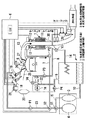
本実施形態は、図1に示すような構成となっている。以下、この図に従って詳細に説明する。
水素化ガソリンは、外部から水素化燃料貯留部4に供給される。水素化燃料貯留部4は、後述する水素分離後の脱水素生成物貯留部3との共有タンクとなっている。
The present embodiment is configured as shown in FIG. Hereinafter, it will be described in detail with reference to this figure.
Hydrogenated gasoline is supplied to the hydrogenated
本態様においては、水素化燃料貯留部4からバルブV1とV2を経由してポンプP1によりインジェクタ19から内燃機関に直接水素化ガソリンを供給することもでき、水素化ガソリンを直接内燃機関の燃料とすることができる。
また、水素化ガソリンは、V1とV2を経由して供給配管7にあるポンプP2により脱水素反応器(反応手段)1に供給することもできる。
In this embodiment, hydrogenated gasoline can also be directly supplied from the
Hydrogenated gasoline can also be supplied to the dehydrogenation reactor (reaction means) 1 via the pump P2 in the supply pipe 7 via V1 and V2.
本態様では、エンジンから排出された排出ガスを排気する排気管を取り巻くようにして、脱水素反応器(反応手段)1を設けており、その中に触媒11があり、これはドーナツ型のハニカム担体の各セルの内壁にアルミナコー卜層を設け、該コート層に触媒たる金属微粒子を担持させたものである。そして、脱水素反応器1は、触媒11に水素化ガソリンを供給するインジェクタ(燃料供給装置)12を備え、供給された水素化ガソリンを排気ガスの熱(排気熱)で加熱された触媒11中で脱水素反応させる。 In this embodiment, a dehydrogenation reactor (reaction means) 1 is provided so as to surround an exhaust pipe for exhausting exhaust gas discharged from the engine, and a catalyst 11 is included therein, which is a donut-shaped honeycomb. An alumina coating layer is provided on the inner wall of each cell of the carrier, and metal fine particles as a catalyst are supported on the coating layer. The dehydrogenation reactor 1 includes an injector (fuel supply device) 12 for supplying hydrogenated gasoline to the catalyst 11, and the supplied hydrogenated gasoline is heated in the catalyst 11 with the heat of exhaust gas (exhaust heat). To dehydrogenate.
脱水素反応器1について、さらに図2を参照して説明する。図2は、脱水素反応器の触媒11の斜視図である。この図に示す通り、触媒11は円筒に穴を開けたドーナツ状の形状であり、該穴に排気管13が貫通できる構造となっている。
The dehydrogenation reactor 1 will be further described with reference to FIG. FIG. 2 is a perspective view of the catalyst 11 of the dehydrogenation reactor. As shown in this figure, the catalyst 11 has a donut shape in which a hole is formed in a cylinder, and the
排気管13は、一端でエンジンのシリンダ5と排気バルブ27を介しで接続され、他端から浄化触媒を介して排出ガスを排気するようになっている(図1参照)。
水素化ガソリンインジェクタ12は、触媒11上に水素化ガソリンを広角に噴霧等して、水素リッチガスを効率良く生成することができる。
The
The
一方、排気管13の下流側には、排気管13に沿うようにして混合気体が通過するための流路30が設けられており、発生した混合気体を挿通する場合に、特に混合気体中の脱水素生成物が冷えて凝縮することなく、気体状態のまま挿通できるようになっている。
On the other hand, on the downstream side of the
また、脱水素反応器1には、バルブV3と水素及び脱水素生成物を排出するための戻し配管14の一端とが接続されており、戻し配管14によって分離装置2と連通されている。
分離装置2では、水素及び脱水素生成物が冷却され、脱水素生成物が液化してタンク下部に貯まり水素と分離される。
分離装置2の上部には、ポンプP4と逆止弁とを備えた水素リッチガスを挿通するための配管17の一端が接続されており、底部に配管10が接続され、脱水素生成物貯留部3に接続している。分離された水素リッチガスは、配管17を挿通して分離装置2から排出され、また分離装置2に貯留された脱水素生成物は、配管10を介し脱水素生成物貯留部3に導入できるようになっている。
The dehydrogenation reactor 1 is connected to a valve V3 and one end of a
In the
One end of a pipe 17 for inserting a hydrogen rich gas provided with a pump P4 and a check valve is connected to the upper part of the
エンジンのシリンダ5には、燃料を空気や水素と共に混合ガスとしてシリンダ内に供給するための吸気管25と、排出ガスを排気するための排気管13とがそれぞれ吸気バルブ26、排気バルブ27を介して接続されている。また、シリンダヘッドには、シリンダ内の混合ガスに点火するための点火プラグ24が設けられている。
The
吸気管25には、配管17の他端に接続された水素供給用インジェクタ18と、ポンプP1を備えた水素化ガソリン(又は脱水素生成物たるガソリン)を供給するための供給配管23の一端に接続されたガソリン供給用インジェクタ19とが設けられている。水素供給用インジェクタ18は、配管17によって分離装置2と連通され、吸気管25内に水素を添加できるようになっており、またガソリン供給用インジェクタ19は、供給配管23と連通され、吸気管25内にガソリンを供給できるようになっている。これにより、水素およびガソリンを含む混合ガスをシリンダ内に供給することができる。
The
配管17には、水素を貯えると共に水素供給用インジェクタ18に水素を供給するバッファタンク20と、水素供給用インジェクタ18への水素供給圧を所望圧に制御するためのレギュレータ21が設けられている。更に、ポンプP1とバッファタンク20との間には水素供給圧が過大とならないようにリリーフ弁(リリーフバルブ)を備えた迂路が設けられている。
The pipe 17 is provided with a
水素化燃料貯留部4は、主燃料である水素化ガソリンを貯留し、上部に設けられた供給配管23を通じてガソリン供給用インジェクタ19に水素化ガソリンを供給できるようになっているが、水素分離後の脱水素生成物貯留部3からもバルブV1を経由して、同様にガソリン供給用インジェクタ19にガソリン(脱水素生成物)を供給できるようになっている。
The hydrogenated
また、排気管13における脱水素反応器1のさらに下流には、排出ガス中の窒素酸化物(NOx)濃度を検出するNOxセンサ及び空燃比計測のためのA/Fセンサ、3元触媒(浄化触媒)の上流側で排出ガス中に水素リッチガスを添加するための水素添加インジェクタ28、並びにグロープラグが設けられている。
Further, further downstream of the dehydrogenation reactor 1 in the
水素添加インジェクタ24は、配管17と連通するバルブV4とポンプP3とを備えた配管8の一端で接続されており、分離装置2で分離された水素リッチガスの一部を排気管13に供給できるようになっている。排気管13中の排出ガスに水素リッチガスを添加すると共にグロープラグで燃焼させることにより、排気される排出ガスを更に浄化することができる。
The hydrogen addition injector 24 is connected at one end of a pipe 8 having a valve V4 communicating with the pipe 17 and a pump P3 so that a part of the hydrogen rich gas separated by the
上記の水素化ガソリンインジェクタ12、水素供給用インジェクタ18、ガソリン供給用イシジエクタ19、点火プラグ24、NOxセンサ及びA/Fセンサ、水素添加インジェクタ24並びにグロープラグ等は、各々制御装置(ECU)6と電気的に接続されており、ECU6によって制御されている。
The
以下、本実施形態の制御装置(ECU)6による制御について説明する。なお、ここでは本発明に関係する水素リッチガス発生制御のみを説明する。
まず、IGスイッチがオンされると、まずエンジンが始動し、温度センサを用いて触媒11の温度Tを取り込み、触媒温度Tが予め定められた所定温度T0以下か否かを判断する。このとき、触媒温度Tが所定温度T0以下の場合には再度触媒温度Tを取り込み、触媒温度Tが所定温度T0を超えている、あるいは温度T0を超えた場合には、ECU6と電気的に繋がる図示しない制御用ドライバにより各々のインジェクタ12から予め定めた所定量で水素化ガソリンが供給される。
Hereinafter, control by the control device (ECU) 6 of the present embodiment will be described. Here, only the hydrogen rich gas generation control related to the present invention will be described.
First, when the IG switch is turned on, the engine is first started, the temperature T of the catalyst 11 is taken in using a temperature sensor, and it is determined whether or not the catalyst temperature T is equal to or lower than a predetermined temperature T0. At this time, when the catalyst temperature T is equal to or lower than the predetermined temperature T0, the catalyst temperature T is taken in again, and when the catalyst temperature T exceeds the predetermined temperature T0 or exceeds the temperature T0, the
上記の所定温度は、250〜500℃、好ましくは250〜350℃の間の温度である。この理由は、所定温度が250℃未満であると目的とする脱水素反応の高い反応速度、換言すれば内燃機関や他の水素使用装置の高性能が得られないことがあり、350℃を越えるとカーボンデポジットが生じる可能性を持ち、500℃を越えると実用的でないからである。 Said predetermined temperature is a temperature between 250-500 degreeC, Preferably it is 250-350 degreeC. This is because if the predetermined temperature is less than 250 ° C., the high reaction rate of the intended dehydrogenation reaction, in other words, the high performance of the internal combustion engine or other hydrogen using device may not be obtained, and it exceeds 350 ° C. This is because there is a possibility that carbon deposits are generated, and if it exceeds 500 ° C., it is not practical.
本実施形態では、IGスイッチがオンされると、ガソリン供給用インジェクタ19から供給されたガソリン(又は水素化ガソリン)に空気と共に水素添加インジェクタ18からバッファタンク20内の水素が添加された混合ガスによってエンジンが始動する。始動後シリンダから排出された排出ガスによって排気管13が加熱され、担持された触媒が所定の温度にまで達すると、ポンプP2を駆動して水素化燃料貯留部4から水素化ガソリンが供給配管7を挿通して脱水素反応器1の触媒11上に供給される。脱水素反応して発生した水素リッチガス(蒸発した残存水素化ガソリンを含んでもよい。)は脱水素生成物と共に排出管14を挿通して分離装置2に送られる。
In the present embodiment, when the IG switch is turned on, the gasoline (or hydrogenated gasoline) supplied from the
分離装置2に供給された水素リッチガスは、冷却されると共にガス中の脱水素生成物は液化して水素リッチガスと分離される。分離された水素リッチガスは、配管17を挿通してバッファタンク20に供給、貯蔵されると共に、配管17から分岐する配管8と繋がる水素添加インジェクタ24から排気管13中にも供給される。バッファタンク20に供給、貯蔵された水素リッチガスは、ガソリンの供給タイミングに合わせて水素供給用インジェクタ18から吸気管25に供給される。以上のように、エンジンの排気熱を利用した車両内での水素生成が可能であり、高純度の水素リッチガスを継続的にエンジンに供給することで排出ガスの浄化、低燃費化が実現されると共に、同時に排出ガスに水素添加し、燃焼させることで排出ガスを更に浄化することができる。
The hydrogen rich gas supplied to the
車両を停止させてイグニッション(IG)スイッチをオフした場合は、エンジンが停止されると共に、ポンプP2の駆動を停止し水素化ガソリンインジェクタ12からの水素化ガソリン供給を停止することにより水素リッチガスの生成を停止させる。水素化ガソリン供給を停止した後も少量の水素リッチガスが発生するため、バルブV3を開き発生した水素リッチガスを分離装置2を経由してバッファタンク20に貯蔵する。
When the vehicle is stopped and the ignition (IG) switch is turned off, the engine is stopped, the pump P2 is stopped, and the hydrogenated gasoline supply from the
エシジン停止後脱水素反応器内が冷却された後、脱水素生成物が液化し器内に残った液は、バルブV3を開き分離装置2に導入される。脱水素生成物はここで冷却、凝縮されてタンク底部に沈降、貯留される。
After the inside of the dehydrogenation reactor is cooled after the ecidin is stopped, the dehydrogenation product is liquefied and the liquid remaining in the reactor is introduced into the
上述した実施形態では、燃料として水素化ガソリンを用いた例を中心に説明したが、既述の水素化ガソリン以外の燃料を用いた場合においても同様である。また、内燃機関として、ガソリンエンジンを例に説明したが、本発明はガソリンエンジン以外のディーゼルエシジシや水素エンジン等の内燃機関に適用することもできる。 In the embodiment described above, the example using hydrogenated gasoline as the fuel has been mainly described. However, the same applies to the case where fuel other than the hydrogenated gasoline described above is used. Moreover, although the gasoline engine was demonstrated to the example as an internal combustion engine, this invention can also be applied to internal combustion engines, such as a diesel engine other than a gasoline engine, and a hydrogen engine.
また、本発明における水素リッチガス生成装置により生成された水素は、ガソリンや軽油等の燃料に水素添加して燃焼させる内燃機関(ガソリンエンジン、ディーゼルエンジン等)や水素エンジンの燃料として、あるいは車両に搭載された燃料電池などの水素使用装置供給用として用いることができる。 In addition, the hydrogen produced by the hydrogen rich gas production device according to the present invention is used as fuel for an internal combustion engine (gasoline engine, diesel engine, etc.) or a hydrogen engine that is hydrogenated to fuel such as gasoline or light oil, or mounted on a vehicle. It can be used for supplying hydrogen using devices such as fuel cells.
また、上述した実施の形態1においては、水素化ガソリン、水素リッチガス、および脱水素生成物の使い分けについて、特に言及していないが、それらは、以下のように使い分けることとしてもよい。すなわち、内燃機関の始動時には、水素リッチガスだけを燃料として供給することとしてもよい。冷間時にガソリンが燃料とされる場合には、低温環境下での低い気化性がエミッション特性や始動性を悪化させる原因となる。これに対して、始動時に水素リッチガスのみを燃料とすることとすれば、その影響を排除して、極めて良好な始動性とエミッション特性とを実現することができる。 Moreover, in Embodiment 1 mentioned above, although there is no particular mention about the proper use of hydrogenated gasoline, hydrogen rich gas, and a dehydrogenation product, they are good also as follows. That is, only the hydrogen rich gas may be supplied as fuel when starting the internal combustion engine. When gasoline is used as a fuel during cold weather, low vaporization in a low-temperature environment causes the emission characteristics and startability to deteriorate. On the other hand, if only the hydrogen rich gas is used as the fuel at the start, the influence can be eliminated and extremely good startability and emission characteristics can be realized.
また、内燃機関の始動後は、原則として、水素リッチガスと脱水素生成物とを燃料として内燃機関に供給することとしてもよい。より具体的には、脱水素生成物の残量を監視したうえで、その供給が可能である場合には、ガソリンの供給が要求される状況下では、常に、水素化ガソリンではなく、脱水素生成物を供給することとしてもよい。また、水素リッチガスの残量を監視したうえで、その供給が可能である場合には、常に、内燃機関に対して水素リッチガスを供給することとしてもよい。 Further, after the internal combustion engine is started, in principle, the hydrogen rich gas and the dehydrogenation product may be supplied as fuel to the internal combustion engine. More specifically, if the dehydrogenation product remaining amount is monitored and can be supplied, the dehydrogenation product is always used instead of hydrogenated gasoline in situations where the supply of gasoline is required. The product may be supplied. Further, when the hydrogen rich gas can be supplied after monitoring the remaining amount of the hydrogen rich gas, the hydrogen rich gas may always be supplied to the internal combustion engine.
水素化ガソリンは、一般的なガソリンに対して水素を添加したものである。一方、脱水素生成物は、その水素化ガソリンから水素を脱離させたものであり、一般的なガソリンと実質的に同様の成分を有するものである。燃料のオクタン価は、含有成分に対して水素が添加されることにより一般に低下する。このため、水素化ガソリンは、脱水素生成物に比して、低いオクタン価を示し、内燃機関のノッキングをより発生させ易いという特性を有している。 Hydrogenated gasoline is obtained by adding hydrogen to general gasoline. On the other hand, the dehydrogenation product is obtained by desorbing hydrogen from the hydrogenated gasoline, and has substantially the same components as general gasoline. The octane number of the fuel is generally lowered by adding hydrogen to the contained components. For this reason, hydrogenated gasoline has a low octane number as compared with a dehydrogenated product, and has characteristics that it is easier to cause knocking in an internal combustion engine.
上述したように、ガソリン供給が要求される状況下で、原則として脱水素生成物を燃料とすることによれば、内燃機関のノッキングを抑えることが可能である。このため、このような燃料供給の手法によれば、内燃機関の静粛性や出力特性などを可能な限り向上させることが可能である。 As described above, knocking of the internal combustion engine can be suppressed by using the dehydrogenation product as fuel in principle under a situation where gasoline supply is required. For this reason, according to such a fuel supply method, it is possible to improve the quietness and output characteristics of the internal combustion engine as much as possible.
また、ガソリン燃料に対して水素を添加することによれば、燃料の燃焼性を著しく改善することができ、安定した燃焼が確保できる空気過剰率の上限を、その添加がない場合に比して大幅に高めることができる。このため、上述したように、ガソリン燃料に対する水素添加を原則として行うこととすれば、内燃機関の燃費特性を画期的に改善することが可能である。 In addition, by adding hydrogen to gasoline fuel, the combustibility of the fuel can be remarkably improved, and the upper limit of the excess air ratio that can ensure stable combustion is compared with the case without the addition. Can greatly increase. For this reason, as described above, if hydrogen addition to gasoline fuel is performed in principle, it is possible to dramatically improve the fuel consumption characteristics of the internal combustion engine.
また、上述した実施の形態1においては、水素化燃料貯留部4が前記第1の発明における「水素化ガソリンタンク」に、脱水素反応器1および分離装置2が前記第1の発明における「燃料分離手段」に、それぞれ相当している。
In the first embodiment described above, the hydrogenated
また、上述した実施の形態1においては、バルブV1,V2、ポンプP1、供給配管23、およびガソリン供給用インジェクタ19が前記第1の発明における「水素化ガソリン供給手段」および「脱水素化ガソリン供給手段」に、ポンプP4、配管17、水素供給用インジェクタ18、およびバッファタンク20が前記第1の発明における「水素リッチガス供給手段」に、それぞれ相当している。また、ECU6が、内燃機関の運転状態に応じて、供給するべき燃料を選択することにより前記第1の発明における「燃料選択手段」が、その選択に応じてバルブV1,V2、ポンプP1,P2、水素供給用インジェクタ18およびガソリン供給用インジェクタ19を制御することにより前記第1の発明における「燃料供給制御手段」が、それぞれ実現されている。
In the first embodiment described above, the valves V1 and V2, the pump P1, the
また、上述した実施の形態1においては、ECU6に、ガソリン供給の必要性を判断させることにより前記第1の発明における「ガソリン要否判断手段」を、脱水素生成物が供給可能な程度に存在しているか否かを判断させることにより前記第1の発明における「脱水素化ガソリン供給可否判断手段」を、それぞれ実現することができる。更に、ここでは、ECU6に、水素リッチガスが供給可能な程度に存在しているか否かを判断させることにより前記第2の発明における「水素リッチガス供給可否判断手段」を実現することができる。
Further, in the first embodiment described above, the “gasoline necessity determination means” in the first aspect of the present invention is present to the extent that the dehydrogenated product can be supplied by causing the
(第2実施形態)
[実施の形態2の構成]
次に、図3乃至図5を参照して、本発明の実施の形態2について説明する。図2は、本実施形態の水素利用内燃機関の構成を説明するための図である。本実施形態のシステムは、内燃機関40を備えている。内燃機関40には、吸気管42および排気管44が連通している。
(Second Embodiment)
[Configuration of Embodiment 2]
Next, a second embodiment of the present invention will be described with reference to FIGS. FIG. 2 is a diagram for explaining the configuration of the hydrogen-utilized internal combustion engine of the present embodiment. The system of this embodiment includes an
吸気管42には、吸入空気量を制御するためのスロットルバルブ46が組み込まれている。スロットルバルブ46の下流には、水素供給用インジェクタ48が配置されている。また、内燃機関40の吸気ポートには、ガソリン供給用インジェクタ50が配置されている。これらのインジェクタ48,50は、それぞれ実施の形態1における水素供給用インジェクタ48およびガソリン供給用インジェクタ50と同じ構成および機能を有している。
A
すなわち、水素供給用インジェクタ48は、後述するように、所定の圧力で水素リッチガスの供給を受けており、外部から供給される駆動信号を受けて開弁することにより、その開弁の時間に応じた量の水素リッチガスを吸気管42の内部に噴射することができる。また、ガソリン供給用インジェクタ50も、後述するように、所定の圧力でガソリンの供給を受けており、外部から供給される駆動信号を受けて開弁することにより、その開弁の時間に応じた量のガソリンを吸気ポート内に噴射することができる。
That is, as will be described later, the
排気管44には、脱水素反応器52が装着されている。また、脱水素反応器52の上部には、水素化ガソリンインジェクタ54が組み付けられている。これらは、何れも実施の形態1における脱水素反応器1及び水素化ガソリンインジェクタ12と、実質的に同様に構成されている。
A
すなわち、水素化ガソリンインジェクタ54は、後述するように、所定の圧力で水素化ガソリンの供給を受けており、外部から供給される駆動信号を受けて開弁することにより、その開弁の時間に応じた量の水素化ガソリンを脱水素反応器52の内部に供給することができる。また、脱水素反応器52は、排気管44から放射される排気熱を利用して、上記の如く供給される水素化ガソリンを水素リッチガスと脱水素化ガソリンとに分離し、それらをその下部から流出させる機能を有している。
That is, as will be described later, the
排気管44には、脱水素反応器52の下流において、O2センサ56およびNOxセンサ58が組み込まれている。O2センサ56は、排気ガス中の酸素の有無を基礎として、排気空燃比に応じた出力を発するセンサである。また、NOxセンサ58は、排気ガス中のNOx濃度に応じた出力を発するセンサである。これらのセンサ56,58の下流には、排気ガスを浄化するための触媒60が配置されている。
In the exhaust pipe 44, an O 2 sensor 56 and a
本実施形態のシステムは、水素化ガソリンタンク62を備えている。水素化ガソリンタンク62は、実施の形態1における水素化燃料貯留部3に対応するものであり、その中には、一般的なガソリンに比して有機ハイドライドを多量に含む水素化ガソリンが貯留される。ここで、「有機ハイドライド」とは、300℃程度の温度で脱水素反応を起こすHC成分であり、具体的には、既述したようにデカリンやシクロヘキサンがこれに該当する。
The system of the present embodiment includes a
通常のガソリン(LFT−1C)には、トルエンが40%程度含まれている。トルエンを水素化すると、有機ハイドライドであるメチルシクロヘキサンを生成することができる。つまり、通常のガソリンを原料として、その中に含まれるトルエンを水素化すると、メチルシクロヘキサンを40%程度含有する水素化ガソリンを生成することができる。本実施形態では、便宜上、水素化ガソリンタンク62には、このような組成を有する水素化ガソリンが給油されるものとする。
Ordinary gasoline (LFT-1C) contains about 40% of toluene. When toluene is hydrogenated, methylcyclohexane, which is an organic hydride, can be produced. That is, hydrogenation gasoline containing about 40% of methylcyclohexane can be generated by hydrogenating toluene contained in ordinary gasoline as a raw material. In the present embodiment, for the sake of convenience, it is assumed that the
水素化ガソリンタンク62には、水素化ガソリン供給管64が連通している。水素化ガソリン供給管64は、その途中にポンプ66を備え、その端部において水素化ガソリンインジェクタ54に連通している。水素化ガソリンタンク62内の水素化ガソリンは、内燃機関の運転中に、ポンプ66により汲み上げられて、所定の圧力で水素化ガソリンインジェクタ54に供給される。
A hydrogenated
水素化ガソリンインジェクタ54は、上述した通り、脱水素反応器52の上部に組み付けられている。脱水素反応器52は、排気熱を利用して水素化ガソリンを処理するための装置である。このため、内燃機関の運転中は、脱水素反応器52の内部は、300℃を超える温度に上昇する。
The
水素化ガソリンインジェクタ54は、その内部温度に直接晒されるのを避けるべく、脱水素反応器52の上方空間に主要部分が突出するように組み付けられている。このため、本実施形態のシステムによれば、水素化ガソリンインジェクタ54の温度が、不当に高温となることはない。
The
尚、図3に示すシステムでは、水素化ガソリンインジェクタ54を空冷することとしているが、その冷却の手法はこれに限定されるものではない。例えば、内燃機関40の冷却水を水素化ガソリンインジェクタ54の周囲に導くための冷却水通路を設けて、水素化ガソリンインジェクタ54を水冷することとしても良い。
In the system shown in FIG. 3, the
脱水素反応器52の内部には、反応室が形成されている。水素化ガソリンインジェクタ54から噴射された燃料は、その反応室の内部で水素リッチガスと脱水素化ガソリンとに分離され、その底部に導かれる。反応室の底部には、管路68を介して、分離装置70が連通している。
A reaction chamber is formed inside the
既述した通り、本実施形態において用いられる水素化ガソリンは、通常のガソリンに含まれているトルエンを、有機ハイドライド化したものである。従って、その水素化ガソリンに脱水素処理を施せば、その結果生成されるのは、水素リッチガスと通常のガソリンである。このため、脱水素反応器52から分離装置7へは、具体的には、水素リッチガスと、通常のガソリンとの混合物が供給されることになる。
As described above, the hydrogenated gasoline used in the present embodiment is obtained by organically hydrating toluene contained in normal gasoline. Therefore, if the hydrogenated gasoline is subjected to a dehydrogenation treatment, hydrogen-rich gas and ordinary gasoline are generated as a result. For this reason, specifically, a mixture of hydrogen-rich gas and normal gasoline is supplied from the
分離装置70は、実施の形態1における分離装置2と同様の構造および機能を有している。すなわち、分離装置70は、脱水素反応器52から供給される高温の水素リッチガスおよび脱水素化ガソリン(通常のガソリン)を冷却して、それらを分離する機能を有している。分離装置70は、内燃機関40と同様に冷却水の循環により水冷されている。このため、分離装置70は、効率良く水素リッチガス及び脱水素化ガソリンを冷却することができる。
分離装置70の底部には、冷却されることにより液化した脱水素化ガソリンを貯留しておくための液体貯留スペースが設けられている。また、その貯留スペースの上方には、気体のまま残存する水素リッチガスを貯留するための気体貯留スペースが確保されている。分離装置70には、液体貯留スペースに連通するようにガソリン管路72が連通していると共に、気体貯留スペースに連通するように水素管路74が連通している。
A liquid storage space for storing dehydrogenated gasoline liquefied by cooling is provided at the bottom of the
ガソリン管路72は、ガソリンバッファタンク76に連通している。ガソリンバッファタンク76は、実施の形態1における脱水素生成物貯留部4に相当するタンクである。図3には、水素化ガソリンタンク62とガソリンバッファタンク76とが離れた位置に配置された構成が示されているが、その構成はこれに限定されるものではない。すなわち、実施の形態1における水素化燃料貯留部3および脱水素生成物貯留部4の場合と同様に、それらは、単一の筐体に収めることとしてもよい。
The
ガソリンバッファタンク76には、液量センサ78が組み付けられている。液量センサ78は、その内部に貯留されている脱水素化ガソリンの液量に応じた出力を発するセンサである。また、ガソリンバッファタンク76には、ガソリン供給管80が連通している。ガソリン供給管80は、その途中にポンプ82を備え、その端部においてガソリン供給用インジェクタ50に連通している。ガソリンバッファタンク76内の脱水素化ガソリンは、内燃機関の運転中に、ポンプ82により汲み上げられて、所定の圧力でガソリン供給用インジェクタ50に供給される。
A
水素管路74は、水素バッファタンク84に連通している。また、水素管路74には、分離装置70内の水素リッチガスを水素バッファタンク84に圧送するためのポンプ86と、ポンプ86の吐出側圧力が過大となるのを防ぐためのリリーフ弁88が組み込まれている。ポンプ86およびリリーフ弁88によれば、水素バッファタンク84内に、その内圧が過剰とならない範囲で水素リッチガスを送り込むことができる。
The
水素バッファタンク84は、実施の形態1におけるバッファタンク20に相当するタンクである。但し、本実施形態では、水素バッファタンク84に圧力センサ90が組み付けられている。圧力センサ90は、水素バッファタンク84の内圧に応じた出力を発するセンサである。圧力センサ90の出力によれば、水素バッファタンク84内に貯留されている水素リッチガスの量を推定することができる。
The
水素バッファタンク84には、水素供給管92が連通している。水素供給管92は、その途中にレギュレータ94を備え、その端部において水素供給用インジェクタ48に連通している。このような構成によれば、水素供給用インジェクタ48には、水素バッファタンク84に水素リッチガスが十分に貯留されていることを条件に、レギュレータ94により調整される圧力により水素リッチガスが供給される。
A
本実施形態のシステムは、図3に示すように、ECU96を備えている。ECU96は、実施の形態1におけるECU6と同様に、本実施形態のシステムを制御する機能を有している。すなわち、ECU96には、上述したO2センサ56、NOxセンサ58、液量センサ78および圧力センサ90などの各種センサの出力が供給されている。また、ECU96には、上述したポンプ66,82,86、並びにインジェクタ48,50,54などのアクチュエータが接続されている。ECU96は、それらのセンサ出力を基礎として所定の処理を行うことにより、上述した各種のアクチュエータを適当に駆動することができる。
The system of the present embodiment includes an
[実施の形態2の動作の概要]
図4は、本実施形態において用いられる水素化ガソリンと脱水素化ガソリンとの間で生ずる基本の反応を説明するための図である。既述した通り、本実施形態では、40%程度含む水素化ガソリンが用いられる。メチルシクロヘキサンC7H14を300℃程度に加熱すると、次式に示すような脱水素化反応が生じ、トルエンC7H8と水素H2が生成される。
C7H14→C7H8+3H2 ・・・(1)
[Outline of Operation of Embodiment 2]
FIG. 4 is a diagram for explaining a basic reaction that occurs between hydrogenated gasoline and dehydrogenated gasoline used in the present embodiment. As described above, in this embodiment, hydrogenated gasoline containing about 40% is used. When methylcyclohexane C 7 H 14 is heated to about 300 ° C., a dehydrogenation reaction as shown in the following formula occurs, and toluene C 7 H 8 and hydrogen H 2 are generated.
C 7 H 14 → C 7 H 8 + 3H 2 (1)
反対に、トルエンC7H8に水素化処理を施すと、次式に示すような反応が生じ、メチルシクロヘキサンC7H14が生成される。
C7H8+3H2→C7H14 ・・・(2)
On the other hand, when toluene C 7 H 8 is subjected to a hydrogenation treatment, a reaction represented by the following formula occurs and methylcyclohexane C 7 H 14 is produced.
C 7 H 8 + 3H 2 → C 7 H 14 (2)
本実施形態のシステムでは、排気管44の温度が十分に上昇した状態で水素化ガソリンインジェクタ54から脱水素反応器62に水素化ガソリンを供給することにより、その中で上記(1)の脱水素反応を生じさせることができる。その結果、1molのメチルシクロヘキサンC7H14から1molのトルエンC7H8と3molの水素H2を生成することができる。
In the system of the present embodiment, hydrogenated gasoline is supplied from the
ところで、本実施形態のシステムは、上述した通り、内燃機関40に対して、脱水素化ガソリン(通常のガソリン)と、水素リッチガスを供給することができる。ガソリンに適量の水素を混合して燃焼させることとすると、水素が添加されない場合に比して筒内での燃焼を十分に安定化させることができ、混合気中の空気過剰率を大幅に高めることができる。
By the way, the system of this embodiment can supply dehydrogenated gasoline (normal gasoline) and hydrogen rich gas to the
燃料の消費量は、混合気の空気過剰率が高いほど少量となる。また、燃料の消費量が少ないほど、当然に排気エミッションは良好となる。このため、混合気中に水素を添加することとすると、その添加がされない場合に比して、内燃機関40の燃費特性及びエミッション特性を画期的に向上させることができる。
The amount of fuel consumed decreases as the excess air ratio of the air-fuel mixture increases. Also, the lower the fuel consumption, the better the exhaust emission. For this reason, if hydrogen is added to the air-fuel mixture, the fuel consumption characteristics and emission characteristics of the
ところで、混合気中に水素を添加することにより上記の効果を得るためには、ある程度の量の水素を添加することが必要である。具体的には、例えば、ガソリンによる供給熱量の20%程度を水素により供給することとすると、燃費特性やエミッション特性は、効果的に改善することができる。 By the way, in order to obtain the above effect by adding hydrogen to the air-fuel mixture, it is necessary to add a certain amount of hydrogen. Specifically, for example, if about 20% of the amount of heat supplied by gasoline is supplied by hydrogen, fuel consumption characteristics and emission characteristics can be effectively improved.
しかしながら、そのような比率を実現するためには、ガソリン1molに対して、3.36molの水素H2が必要となる。通常のガソリン中に含まれるトルエン比率が40%であるとすると、そのガソリンを水素化することで得られる水素化ガソリン中の1molに含まれるメチルシクロヘキサンは0.4molである。そして、0.4molのメチルシクロヘキサンから生成できる水素H2の量は1.2molである。 However, in order to realize such a ratio, 3.36 mol of hydrogen H 2 is required for 1 mol of gasoline. If the toluene ratio contained in normal gasoline is 40%, methylcyclohexane contained in 1 mol of hydrogenated gasoline obtained by hydrogenating the gasoline is 0.4 mol. The amount of hydrogen H 2 that can be generated from 0.4 mol of methylcyclohexane is 1.2 mol.
つまり、1molの水素化ガソリンを脱水素反応器52に供給すると、1molの通常ガソリンと、1.2molの水素H2が生成される。そして、生成された1molの通常ガソリンを20%の水素添加の条件で消費しようとすれば、3.36molの水素H2が必要となり、結局、3.36−1.2=2.16molの水素H2が不足することとなる。
That is, when 1 mol of hydrogenated gasoline is supplied to the
水素化ガソリンが、仮にメチルシクロヘキサンだけを含むものであったとしても、つまり、100%のメチルシクロヘキサンであったとしても、1molの水素化ガソリンから生成できる水素量は3molに過ぎない。上述した水素添加に比率によれば、この場合であっても、3.36−3=0.36molは水素H2が不足することとなる。このように、水素化ガソリンを原料として水素H2と脱水素化ガソリンを生成し、それらの双方を内燃機関40に供給しようとした場合は、脱水素化ガソリンの生成量に対して、水素の生成量が不足気味になるという傾向が生じ易い。
Even if the hydrogenated gasoline contains only methylcyclohexane, that is, 100% methylcyclohexane, the amount of hydrogen that can be generated from 1 mol of hydrogenated gasoline is only 3 mol. According to the ratio to the hydrogenation described above, even in this case, 3.36-3 = 0.36 mol is insufficient for hydrogen H 2 . Thus, when hydrogen H 2 and dehydrogenated gasoline are produced using hydrogenated gasoline as a raw material and both of them are to be supplied to the
本実施形態では、原則として、消費される水素H2が脱水素反応器52によって新たに生成されるように水素化ガソリンインジェクタ54による水素化ガソリンの噴射量が決定される。このため、本実施形態のシステムでは、原則として、内燃機関40の運転中に水素が不足するような事態が生ずることはない。
In the present embodiment, in principle, the hydrogenated gasoline injection amount by the
ところが、上記の傾向の下で、十分な量の水素を生成しようとすれば、必然的に、脱水素化ガソリンが過剰に生成されることとなる。つまり、混合気中に適量の水素H2を添加しつつ、そこで消費される水素H2が補われるように水素化ガソリンの脱水素化処理を継続した場合には、脱水素化ガソリンの余剰分が蓄積されて、やがてはガソリンバッファタンク76がガソリンで満たされた状態となる。
However, if a sufficient amount of hydrogen is to be generated under the above-mentioned tendency, the dehydrogenated gasoline is inevitably produced excessively. That is, when adding a suitable amount of hydrogen H 2 to the air-fuel mixture and continuing the dehydrogenation treatment of the hydrogenated gasoline so that the hydrogen H 2 consumed there is supplemented, the excess amount of the dehydrogenated gasoline Is accumulated and eventually the
ガソリンバッファタンク76に脱水素化ガソリンが一杯に貯留された後は、最早脱水素化ガソリンを過剰に生成し続けることはできない。そこで、本実施形態のシステムは、このような状況が形成された場合には、一旦、内燃機関40への水素の供給を停止し、かつ、水素化ガソリンの新たな脱水素化処理を停止し、ある程度の期間は脱水素化ガソリンのみを燃料として内燃機関40を運転させることとした。そして、ガソリンバッファタンク76内に適当なスペースが確保された段階で、再び水素化ガソリンの脱水素処理と、混合気への水素添加とを再開することとした。
After the dehydrogenated gasoline is fully stored in the
[実施の形態2の具体的処理]
図5に示すルーチンでは、先ず、車両のIGスイッチがONとされているか否かが判別される(ステップ100)。その結果、IG=ONの成立が認められない場合は、速やかに今回のルーチンが終了される。
[Specific Processing of Embodiment 2]
In the routine shown in FIG. 5, it is first determined whether or not the IG switch of the vehicle is turned on (step 100). As a result, if the establishment of IG = ON is not recognized, the current routine is immediately terminated.
一方、IG=ONの成立が認められた場合は、次に、内燃機関40の温度Tが、脱水素化処理の実行条件を満たしているか、具体的には、T1≧T≧T0の条件を満たしているかが判断される(ステップ102)。本実施形態のシステムでは、実施の形態1の場合と同様の理由により、内燃機関40の温度Tが350℃以下、かつ、250℃以上の場合に限り、脱水素反応器52による脱水素化処理を実行することとしている。ここでは、具体的には、温度Tがその条件を満たしているか否かが判別される。
On the other hand, if it is confirmed that IG = ON is established, next, whether the temperature T of the
上記ステップ102の処理により、T1≧T≧T0の条件が成立していないと判別された場合は、脱水素化処理を実行するための条件が整っていないと判断できる。この場合は、先ず、脱水素化処理がOFFとされ(ステップ104)。本ステップ104の処理が実行されると、水素化ガソリンインジェクタ54への駆動信号の供給が停止され、脱水素反応器52への水素化ガソリンの供給が禁止される。その結果、水素リッチガスおよび脱水素化ガソリンの新たな生成が禁止される。
If it is determined that the condition of T1 ≧ T ≧ T0 is not satisfied by the process of
次に、水素H2の噴射が可能であるか否かが判別される(ステップ106)。具体的には、圧力センサ90の出力に基づいて推定される水素H2の残量が、供給可能判定量を超えているか否かが判別される。ここで、「供給可能判定量」とは、水素供給用インジェクタ48に対して、レギュレータ94を介して安定した圧力で水素H2を供給するに足る残量として定められた値である。
Next, it is determined whether or not hydrogen H 2 can be injected (step 106). Specifically, it is determined whether or not the remaining amount of hydrogen H2 estimated based on the output of the
上記ステップ106の処理により、水素H2の噴射が可能でないと判別された場合は、内燃機関40を、脱水素化ガソリン、つまり、通常のガソリンのみを燃料として作動させる必要があると判断できる。この場合は、以後、ガソリン噴射制御が実行される(ステップ108)。
If it is determined by the processing in
ECU96には、脱水素化ガソリンのみが燃料として供給される状況下で内燃機関40を安定に作動させるための制御規則と、脱水素化ガソリンと水素H2とが燃料として供給される状況下で内燃機関40を安定に作動させるための制御規則とが記憶されている。ガソリン噴射制御では、前者の規則に従って、燃料噴射量などの制御パラメータが決定されると共に、ガソリン供給用インジェクタ50のみに作動指令が発せられる。つまり、水素供給用インジェクタ48が停止状態に維持されたまま、脱水素化ガソリンのみが供給される前提の下に内燃機関40の制御が行われる。この場合、内燃機関40において、水素を利用しない一般的な内燃機関と同様の運転状態を実現することができる。
The
本実施形態において用いられる脱水素化ガソリンは、既述した通り、通常のガソリンと同様の組成を有するものである。但し、通常のガソリンには、微量ながら有機ハイドライドが含まれている。これに対して、ここで用いられる脱水素化ガソリンは、脱水素の処理が施されたものであるから、有機ハイドライドを実質的に含んでいない。つまり、本実施形態において用いられる脱水素化ガソリンは、通常のガソリンに比して更に高いオクタン価を有するものである。このため、本実施形態のシステムによれば、上述したガソリン噴射制御の実行下においても、厳密には、一般的な内燃機関に比して更に優れた出力特性を得ることができる。 The dehydrogenated gasoline used in this embodiment has the same composition as that of normal gasoline as described above. However, ordinary gasoline contains a small amount of organic hydride. On the other hand, since the dehydrogenated gasoline used here has been subjected to dehydrogenation treatment, it does not substantially contain organic hydride. That is, the dehydrogenated gasoline used in this embodiment has a higher octane number than that of ordinary gasoline. For this reason, according to the system of the present embodiment, even under the execution of the gasoline injection control described above, it is possible to obtain output characteristics that are more excellent than those of a general internal combustion engine.
図5に示すルーチン中、上記ステップ106において、水素H2の噴射が可能であると判断された場合は、水素・ガソリン噴射制御が実行される(ステップ110)。水素・ガソリン噴射制御では、ECU96は、水素H2が添加されることを前提として内燃機関40の制御パラメータを演算し、また、その演算の結果に従って、水素供給用インジェクタ48とガソリン供給用インジェクタ50の双方を駆動する。
In the routine shown in FIG. 5, when it is determined in
より具体的には、ここでは、内燃機関40の運転状態を所定の規則に当てはめることにより、水素リッチガスの目標供給量と脱水素化ガソリンの目標供給量とが算出される。そして、それらの算出結果に基づいて、水素供給用インジェクタ48およびガソリン供給用インジェクタ50の双方が算出される。このような制御によれば、混合気に適量の水素H2が添加されることにより、ガソリン噴射制御が実行される場合に比して著しく優れた燃費特性、出力特性、およびエミッション特性を実現することができる。
More specifically, the target supply amount of hydrogen rich gas and the target supply amount of dehydrogenated gasoline are calculated by applying the operating state of the
図5に示すルーチン中、上記ステップ102において、内燃機関40の温度TがT1≧T≧T0の条件を満たすと判別された場合は、脱水素反応器52により水素化ガソリンを処理するための温度条件が整っていると判断できる。この場合は、次に、ガソリンバッファタンク76内のガソリン量が過剰でないかが判別される(ステップ112)。より具体的には、液量センサ78の出力に基づいて推定される脱水素化ガソリンの量が、ガソリンバッファタンク76の貯留上限量に達してないかが判別される。
In the routine shown in FIG. 5, when it is determined in
既述した通り、本実施形態のシステムでは、内燃機関40に対して水素H2と脱水素化ガソリンの双方が供給される場合には、脱水素化ガソリンの生成量が過剰となり、ガソリンバッファタンク76内の貯留量が徐々に増加する傾向が生じ易い。上記ステップ112において、ガソリン量が過剰であると判断された場合は、これ以上脱水素化ガソリンの貯留量が増やせないと判断できる。この場合、先ず、脱水素化処理がOFFとされる(ステップ114)。
As described above, in the system of the present embodiment, when both hydrogen H 2 and dehydrogenated gasoline are supplied to the
脱水素化処理がOFFとされると、脱水素反応器52への新たな水素化ガソリンの供給が禁止され、脱水素化ガソリン及び水素リッチガスの新たな生成が停止される。このため、上記の処理によれば、ガソリンバッファタンク76内の脱水素化ガソリンが更に増量するのを確実に防ぐことができる。
When the dehydrogenation process is turned off, supply of new hydrogenated gasoline to the
次に、ガソリン優先フラグがONとされる(ステップ116)。ガソリンバッファタンク76に過剰にガソリンが貯留されている場合は、脱水素化ガソリンの消費を促進することが好ましい。ガソリン優先フラグは、そのような状況下でONとされるフラグである。従って、ECU96は、ガソリン優先フラグがONとされている場合には、混合気への水素H2の添加を停止して、脱水素化ガソリンを優先的に使用すべき事情が生じていることを認知することができる。
Next, the gasoline priority flag is turned on (step 116). When gasoline is excessively stored in the
図5に示すルーチンでは、上記ステップ116の処理に次いで、ガソリン優先フラグがONとされているか否かが判別される(ステップ118)。その結果、ガソリン優先フラグがONでないと判断された場合は、必ずしも脱水素化ガソリンの消費を優先させる必要がないと判断できる。この場合は、以後、ステップ106以降の処理が実行され、水素H2の供給が可能か否かに基づいて、ガソリン噴射制御、或いは水素・ガソリン噴射制御が実行される。
In the routine shown in FIG. 5, it is determined whether or not the gasoline priority flag is ON after the processing of step 116 (step 118). As a result, when it is determined that the gasoline priority flag is not ON, it can be determined that it is not always necessary to give priority to the consumption of dehydrogenated gasoline. In this case, thereafter, the processing from
一方、上記ステップ118において、ガソリン優先フラグがONであると判別された場合は、水素H2の供給を停止して、脱水素化ガソリンの消費を促進する必要があると判断できる。この場合は、以後、無条件でステップ108の処理、つまり、ガソリン噴射制御が実行される。
On the other hand, if it is determined in
図5に示すルーチン中、上記ステップ112の条件が否定された場合は、ガソリンバッファタンク76に、更なる脱水素化ガソリンの流入を許容するスペースが存在すると判断できる。この場合は、次に、水素バッファタンク84内の水素リッチガス量が過剰でないかが判別される(ステップ120)。より具体的には、圧力センサ90の出力に基づいて推定される水素リッチガスの量が、水素バッファタンク76の貯留上限量に達してないかが判別される。
In the routine shown in FIG. 5, if the condition in
本実施形態のシステムは、原則として、水素の消費量が補われるように脱水素化の処理を進行させる。このため、通常の運転状況下では、水素バッファタンク84内の水素リッチガス量が過剰となることはない。しかしながら、何らかの事情により水素リッチガスの貯留量が過剰となった場合には、新たな水素リッチガスの生成を停止させることが必要である。このため、上記ステップ120において、水素H2の貯留量が過剰であると判別された場合は、脱水素化処理がOFFとされる(ステップ122)。
In principle, the system of the present embodiment advances the dehydrogenation process so that the consumption of hydrogen is supplemented. For this reason, the amount of hydrogen rich gas in the
また、この場合は、水素バッファタンク84に貯留されている水素リッチガスの消費を促進するべきであるから、ガソリン優先フラグがOFFとされる(ステップ124)。この場合、続くステップ118でガソリン優先フラグがONでないと判断され、次いでステップ106においてH2の噴射が可能であると判断されるため、水素・ガソリン噴射制御が実行される。その結果、水素リッチガスが過剰に貯留された状態が解消される。
In this case, since the consumption of the hydrogen rich gas stored in the
図5に示すルーチン中、上記ステップ120の条件判定が否定された場合は、脱水素化処理を実行するべき条件が整っていると判断できる。この場合は、次に脱水素化処理がONとされる(ステップ126)。脱水素化処理がONとされると、水素化ガソリンインジェクタ54に駆動信号が供給され、脱水素反応器52に適量の水素化ガソリンが供給される。その結果、内燃機関40において燃料として消費される水素リッチガス量を補う量だけの水素リッチガスが新たに生成され、また、その水素リッチガスの生成量に対応した脱水素化ガソリンが新たに生成される。
In the routine shown in FIG. 5, when the condition determination in
ここでは、次に、ガソリンバッファタンク76内の脱水素化ガソリンの処理が完了したか否かが判別される(ステップ128)。ECU96は、上記ステップ112の処理により、ガソリンバッファタンク76内のガソリン量が過剰であると判断された場合は、その後、ガソリンの貯留量が処理完了判定値を下回るまでは脱水素化ガソリンの処理が未完であると判断する。このような判断がなされた場合は、次に、ガソリン優先フラグがONとされる(ステップ130)。この場合、以後、ステップ108においてガソリン噴射制御が実行されるため、脱水素化ガソリンの優先処理が継続される。
Here, it is next determined whether or not the processing of the dehydrogenated gasoline in the
ECU96は、ガソリンバッファタンク76内のガソリン量が上述した処理完了判定値を下回ると、上記ステップ128において、脱水素化ガソリンの処理が完了したと判断する。この場合、次にステップ124の処理が実行され、ガソリン優先フラグがOFFとされる。その結果、以後、水素の噴射が可能か否かに応じて、何れの制御を行うかが選択される状態となる。
When the amount of gasoline in the
以上説明した通り、図5に示すルーチンによれば、内燃機関40の状態、および水素リッチガス並びに脱水素化ガソリンの貯留状態に基づいて、脱水素化ガソリンのみを燃料とする運転モードと、水素及び脱水素化ガソリンを燃料とする運転モードとを適宜切り替えることができる。そして、このような切り替えを行うことにより、2種類の燃料を使用しつつ、それらの消費量の不均衡に影響されることなく、内燃機関40の出力特性、燃費特性、およびエミッション特性を継続的に良好に維持することが可能とされている。
As described above, according to the routine shown in FIG. 5, based on the state of the
つまり、本実施形態のシステムによれば、給油の対象を単一の燃料(水素化ガソリン)としつつ、2つの燃料(水素リッチガスと脱水素化燃料)を用いることによる効果を有効に導き出すことができる。また、このシステムによれば、2種類の燃料の消費量が不均衡であっても、その不均衡を車両上で解消することができる。その結果、ここでは、繁雑なメンテナンス作業を必要とせずに、かつ、それぞれの燃料の消費量を合わせるための制限を課することなく、2種類の燃料の継続的な使用が可能とされている。 That is, according to the system of the present embodiment, the effect of using two fuels (hydrogen-rich gas and dehydrogenated fuel) can be effectively derived while the target of refueling is a single fuel (hydrogenated gasoline). it can. Further, according to this system, even if the consumption amounts of the two types of fuel are imbalanced, the imbalance can be eliminated on the vehicle. As a result, the two types of fuel can be used continuously without the need for complicated maintenance work and without imposing restrictions on matching the consumption of each fuel. .
本実施形態のシステムは、以上説明したような特性を有していることから、一般的な内燃機関と同等の取り扱いの容易性を実現することができる。そのうえで、本実施形態のシステムによれば、一般的な内燃機関に比して、極めて優れた燃費特性、出力特性、およびエミッション特性を実現することができる。 Since the system of the present embodiment has the characteristics as described above, it is possible to realize the same ease of handling as a general internal combustion engine. In addition, according to the system of the present embodiment, it is possible to realize extremely excellent fuel consumption characteristics, output characteristics, and emission characteristics as compared with a general internal combustion engine.
ところで、上述した実施の形態2においては、水素化ガソリンに含まれる有機ハイドライドを、説明の便宜上メチルシクロヘキサンに限定しているが、ここで用いうる水素化ガソリンは、これに限定されるものではない。すなわち、水素化ガソリンに含まれる有機ハイドライドは、300℃程度で脱水素反応を起こすものであれば良く、非環式や環式の炭化水素、および非環式や環式の含酸素炭化水素などであればよい。具体的には、n-ヘキサンやiso-オクタンなどの非環式の炭化水素、或いは、シクロヘキサンやデカリンなどの環式化合物、更にはシクロヘキサノールやシクロヘキサンメタノールなどのアルコール類や、メチル-t-ブチルエーテルなどのエーテル類などであってもよい。
By the way, in
また、上述した実施の形態2においては、内燃機関40に対して水素リッチガスを単独で噴射するモードを用いていないが、本発明はこれに限定されるものではない。例えば、内燃機関40の始動時等に、水素リッチガスを単独で内燃機関40に供給する運転モードを採用することとしてもよい。
Moreover, in
また、上述した実施の形態2においては、分離装置70とは別に、脱水素化ガソリンを貯留するためのガソリンバッファタンク76を設けることとしているが、本発明はこれに限定されるものではない。すなわち、分離装置70の内部に十分な液体貯留スペースが確保できる場合には、ガソリンバッファタンク76を省略することとしてもよい。
In
図6は、上記の変形例の構成を示したものである。図6に示す構成は、ガソリンバッファタンク76が削除されており、ガソリン供給管80が分離装置70に直接接続されている点、および、脱水素化ガソリンの貯留量を検出するための液量センサ78が分離装置70に組み込まれている点を除き、図3に示す構成と同様である。このような構成によれば、ガソリンバッファタンク76が存在しない分だけ、システムを小型化することが可能である。
FIG. 6 shows the configuration of the above modification. In the configuration shown in FIG. 6, the
尚、上述した実施の形態2においては、脱水素反応器52および分離装置70が前記第3の発明における「燃料分離手段」に相当している。
In the second embodiment described above, it is equivalent to "fuel separating unit" in the
また、上述した実施の形態2においては、ポンプ86、水素バッファタンク84、水素供給管92、および水素供給用インジェクタ48が前記第3の発明における「水素リッチガス供給手段」に、ガソリンバッファタンク76、ガソリン供給管80、ポンプ82、ガソリン供給用インジェクタ50が前記第3の発明における「脱水素化ガソリン供給手段」に、それぞれ相当している。また、ECU96が、上記ステップ106および112〜130の処理を実行することにより前記第3の発明における「燃料選択手段」が、上記ステップ108および110の処理を実行することにより前記第3の発明における「燃料供給制御手段」が、それぞれ実現されている。
In the second embodiment described above, the
また、上述した実施の形態2においては、ECU96が、上記ステップ106の処理を実行することにより前記第3の発明における「水素リッチガス残量判定手段」が、上記ステップ108の処理を実行することにより前記第3の発明における「燃料供給量算出手段」が、それぞれ実現されている。更に、ここでは、ECU96が、上記ステップ112の処理を実行することにより前記第4の発明における「脱水素化ガソリン残量判定手段」が実現されている。
Further, in the second embodiment described above, the
本発明の水素利用内燃機関によれば、水素化燃料、水素化燃料から脱水素されて得られた脱水素生成物及び水素から選ばれる1種又は2種以上の燃料を自由に選択して内燃機関に供給でき、エンジン等の内燃機関の吸気系や排気系、燃焼室に水素を供給する場合に、高圧タンクや液体水素タンクなどの搭載や、水素の吸着・吸蔵、燃料の改質によることなく、水素の供給を、水素化燃料の脱水素反応によって生成された水素を用いて行え、エネルギー利用の高効率化、装置全体の小型化、軽量化が図れると共に、クリーンなシステムを構築することができる。 According to the hydrogen-utilizing internal combustion engine of the present invention, an internal combustion engine can be selected by freely selecting one or more fuels selected from hydrogenated fuel, a dehydrogenated product obtained by dehydrogenation from the hydrogenated fuel, and hydrogen. When supplying hydrogen to the intake and exhaust systems and combustion chambers of internal combustion engines such as engines, it is possible to install high-pressure tanks, liquid hydrogen tanks, hydrogen adsorption / storage, and fuel reforming. In addition, hydrogen can be supplied using hydrogen generated by the dehydrogenation reaction of hydrogenated fuel, making it possible to increase the efficiency of energy use, reduce the overall size and weight of the device, and build a clean system. Can do.
1,52 脱水素反応器(反応手段)
2,70 分離装置(分離手段)
3 脱水素生成物貯留部
4 水素化燃料貯留部
6,96 ECU(Electronic Control Unit)
11 触媒
12,54 水素化ガソリンインジェクタ(燃料供給装置)
13 排気管
18,48 水素供給用インジェクタ(水素供給手段)
19,50 ガソリン供給用インジェクタ
62 水素化ガソリンタンク
76 ガソリンバッファタンク
78 液量センサ
80 ガソリン供給管
82,86 ポンプ
84 水素バッファタンク
90 圧力センサ
92 水素供給管
1,52 Dehydrogenation reactor (reaction means)
2,70 Separation device (separation means)
3 Dehydrogenation
11
13
19, 50
Claims (4)
前記水素化ガソリンを、水素リッチガスと脱水素化ガソリンとに分離する燃料分離手段と、
前記水素化ガソリンを内燃機関に供給するための水素化ガソリン供給手段と、
前記水素リッチガスを内燃機関に供給するための水素リッチガス供給手段と、
前記脱水素化ガソリンを内燃機関に供給するための脱水素化ガソリン供給手段と、
前記水素化ガソリン、前記水素リッチガス、および前記脱水素化ガソリンの中から、燃料として用いるべき1種以上の燃料を選択する燃料選択手段と、
選択された燃料が内燃機関に供給されるように、前記水素化ガソリン供給手段、前記水素リッチガス供給手段、および前記脱水素化ガソリン供給手段を制御する燃料供給制御手段と、
ガソリン供給の必要性を判断するガソリン要否判断手段と、
前記脱水素化ガソリンの残留量が供給可能下限量より少ないか否か判断する脱水素化ガソリン供給可否判断手段と、を備え、
前記燃料供給制御手段は、ガソリン供給の必要性が認められており、かつ、前記脱水素化ガソリンの残留量が前記供給可能下限量より少ない状況下でのみ、前記水素化ガソリンの内燃機関への供給を許可することを特徴とする水素利用内燃機関。 A hydrogenated gasoline tank for storing hydrogenated gasoline containing organic hydride, and
Fuel separation means for separating the hydrogenated gasoline into hydrogen-rich gas and dehydrogenated gasoline;
Hydrogenated gasoline supply means for supplying the hydrogenated gasoline to an internal combustion engine;
Hydrogen rich gas supply means for supplying the hydrogen rich gas to the internal combustion engine;
Dehydrogenated gasoline supply means for supplying the dehydrogenated gasoline to an internal combustion engine;
Fuel selection means for selecting one or more types of fuel to be used as fuel from the hydrogenated gasoline, the hydrogen rich gas, and the dehydrogenated gasoline;
Fuel supply control means for controlling the hydrogenated gasoline supply means, the hydrogen rich gas supply means, and the dehydrogenated gasoline supply means so that the selected fuel is supplied to the internal combustion engine;
Gasoline necessity judgment means for judging the necessity of gasoline supply;
Dehydrogenated gasoline supply availability determination means for determining whether or not the residual amount of dehydrogenated gasoline is less than a lower limit of supplyable amount,
The fuel supply control means recognizes the necessity of gasoline supply, and only applies the hydrogenated gasoline to the internal combustion engine under a situation where the residual amount of the dehydrogenated gasoline is less than the lower limit of supplyable amount. A hydrogen-utilized internal combustion engine characterized by permitting supply .
前記燃料供給制御手段は、前記水素リッチガスおよび前記脱水素化ガソリンの双方が供給可能な状況下では、前記水素リッチガスの残留量に関わらず、常にそれらの組み合わせを燃料として内燃機関に供給することを特徴とする請求項1記載の水素利用内燃機関。 Hydrogen rich gas supply availability determination means for determining whether to supply the hydrogen rich gas;
The fuel supply control means always supplies a combination of these as fuel to the internal combustion engine, regardless of the residual amount of the hydrogen-rich gas , in a situation where both the hydrogen-rich gas and the dehydrogenated gasoline can be supplied. 2. The internal combustion engine using hydrogen according to claim 1 , wherein
前記水素化ガソリンを、水素リッチガスと脱水素化ガソリンとに分離する燃料分離手段と、
前記水素リッチガスを内燃機関に供給するための水素リッチガス供給手段と、
前記脱水素化ガソリンを内燃機関に供給するための脱水素化ガソリン供給手段と、
前記水素リッチガスおよび前記脱水素化ガソリンの中から、燃料として用いるべき1種以上の燃料を選択する燃料選択手段と、
選択された燃料が内燃機関に供給されるように、前記水素リッチガス供給手段および前記脱水素化ガソリン供給手段を制御する燃料供給制御手段と、
前記水素リッチガスを貯留する水素リッチガスタンクと、
前記水素リッチガスの残量が供給可能判定量を超えているか否かを判断する水素リッチガス残量判定手段と、
前記脱水素化ガソリンのみが内燃機関に供給されることを前提に、その脱水素化ガソリンの燃料供給量を算出する燃料供給量算出手段と、を備え、
前記燃料供給制御手段は、前記水素リッチガスの残量が前記供給可能判定量以下である状況下では、前記燃料供給量算出手段により算出された燃料供給量に従って、前記脱水素化ガソリンのみを内燃機関に供給することを特徴とする水素利用内燃機関。 A hydrogenated gasoline tank for storing hydrogenated gasoline containing organic hydride, and
Fuel separation means for separating the hydrogenated gasoline into hydrogen-rich gas and dehydrogenated gasoline;
Hydrogen rich gas supply means for supplying the hydrogen rich gas to the internal combustion engine;
Dehydrogenated gasoline supply means for supplying the dehydrogenated gasoline to an internal combustion engine;
Fuel selection means for selecting one or more types of fuel to be used as fuel from the hydrogen-rich gas and the dehydrogenated gasoline;
Fuel supply control means for controlling the hydrogen-rich gas supply means and the dehydrogenated gasoline supply means so that the selected fuel is supplied to the internal combustion engine;
A hydrogen rich gas tank for storing the hydrogen rich gas;
Hydrogen rich gas remaining amount determining means for determining whether or not the remaining amount of hydrogen rich gas exceeds a supplyable determination amount ;
On the assumption that only the dehydrogenated gasoline is supplied to the internal combustion engine, fuel supply amount calculating means for calculating the fuel supply amount of the dehydrogenated gasoline , and
In the situation where the remaining amount of the hydrogen-rich gas is less than or equal to the supplyable determination amount , the fuel supply control means only converts the dehydrogenated gasoline into an internal combustion engine according to the fuel supply amount calculated by the fuel supply amount calculation means. hydrogen utilization engine you and supplying to.
前記脱水素化ガソリンの残量が貯留上限量に達しているか否かを判断する脱水素化ガソリン残量判定手段と、を備え、
前記燃料分離手段は、前記水素リッチガスの消費量が補われるように前記水素化ガソリンを前記水素リッチガスと前記脱水素化ガソリンとに分離する処理を実行し、
前記燃料供給制御手段は、前記脱水素化ガソリンの残量が前記貯留上限量に達する状況下では、前記脱水素化ガソリンのみを内燃機関に供給することを特徴とする請求項3記載の水素利用内燃機関。 A dehydrogenated gasoline tank for storing the dehydrogenated gasoline;
A dehydrogenated gasoline remaining amount determining means for determining whether or not the remaining amount of the dehydrogenated gasoline has reached a storage upper limit amount,
The fuel separation means performs a process of separating the hydrogenated gasoline into the hydrogen-rich gas and the dehydrogenated gasoline so that consumption of the hydrogen-rich gas is supplemented,
4. The use of hydrogen according to claim 3, wherein the fuel supply control means supplies only the dehydrogenated gasoline to the internal combustion engine in a situation where the remaining amount of the dehydrogenated gasoline reaches the upper limit of storage. Internal combustion engine.
Priority Applications (8)
| Application Number | Priority Date | Filing Date | Title |
|---|---|---|---|
| JP2004116609A JP4039383B2 (en) | 2003-10-21 | 2004-04-12 | Internal combustion engine using hydrogen |
| KR1020067007626A KR100783345B1 (en) | 2003-10-21 | 2004-10-06 | Internal combustion engine utilizing hydrogen |
| ES04773733T ES2345107T3 (en) | 2003-10-21 | 2004-10-06 | INTERNAL COMBUSTION ENGINE THAT USES HYDROGEN. |
| PCT/JP2004/015104 WO2005038228A1 (en) | 2003-10-21 | 2004-10-06 | Internal combustion engine utilizing hydrogen |
| EP04773733A EP1691065B1 (en) | 2003-10-21 | 2004-10-06 | Internal combustion engine utilizing hydrogen |
| EP09150855A EP2154357A1 (en) | 2003-10-21 | 2004-10-06 | Hydrogen-fueled internal combustion engine |
| US10/572,904 US7448348B2 (en) | 2003-10-21 | 2004-10-06 | Hydrogen-fueled internal combustion engine |
| DE602004028040T DE602004028040D1 (en) | 2003-10-21 | 2004-10-06 |
Applications Claiming Priority (2)
| Application Number | Priority Date | Filing Date | Title |
|---|---|---|---|
| JP2003360152 | 2003-10-21 | ||
| JP2004116609A JP4039383B2 (en) | 2003-10-21 | 2004-04-12 | Internal combustion engine using hydrogen |
Publications (2)
| Publication Number | Publication Date |
|---|---|
| JP2005147124A JP2005147124A (en) | 2005-06-09 |
| JP4039383B2 true JP4039383B2 (en) | 2008-01-30 |
Family
ID=34467793
Family Applications (1)
| Application Number | Title | Priority Date | Filing Date |
|---|---|---|---|
| JP2004116609A Expired - Fee Related JP4039383B2 (en) | 2003-10-21 | 2004-04-12 | Internal combustion engine using hydrogen |
Country Status (7)
| Country | Link |
|---|---|
| US (1) | US7448348B2 (en) |
| EP (2) | EP1691065B1 (en) |
| JP (1) | JP4039383B2 (en) |
| KR (1) | KR100783345B1 (en) |
| DE (1) | DE602004028040D1 (en) |
| ES (1) | ES2345107T3 (en) |
| WO (1) | WO2005038228A1 (en) |
Families Citing this family (91)
| Publication number | Priority date | Publication date | Assignee | Title |
|---|---|---|---|---|
| US6376708B1 (en) | 2000-04-11 | 2002-04-23 | Monsanto Technology Llc | Process and catalyst for dehydrogenating primary alcohols to make carboxylic acid salts |
| WO2004035466A1 (en) | 2002-10-18 | 2004-04-29 | Monsanto Technology Llc | Use of metal supported copper catalysts for reforming alcohols |
| JP2006248814A (en) * | 2005-03-09 | 2006-09-21 | Hitachi Ltd | Apparatus and method for feeding hydrogen |
| RU2304462C2 (en) * | 2005-09-30 | 2007-08-20 | Общество с ограниченной ответственностью "ЭНВАЙРОКЕТ" | Method and materials for storing hydrogen |
| US7640912B2 (en) * | 2005-11-30 | 2010-01-05 | Ford Global Technologies, Llc | System and method for engine air-fuel ratio control |
| US7647916B2 (en) * | 2005-11-30 | 2010-01-19 | Ford Global Technologies, Llc | Engine with two port fuel injectors |
| US7730872B2 (en) * | 2005-11-30 | 2010-06-08 | Ford Global Technologies, Llc | Engine with water and/or ethanol direct injection plus gas port fuel injectors |
| US7406947B2 (en) | 2005-11-30 | 2008-08-05 | Ford Global Technologies, Llc | System and method for tip-in knock compensation |
| US7877189B2 (en) * | 2005-11-30 | 2011-01-25 | Ford Global Technologies, Llc | Fuel mass control for ethanol direct injection plus gasoline port fuel injection |
| US7412966B2 (en) * | 2005-11-30 | 2008-08-19 | Ford Global Technologies, Llc | Engine output control system and method |
| US7302933B2 (en) * | 2005-11-30 | 2007-12-04 | Ford Global Technologies Llc | System and method for engine with fuel vapor purging |
| US7594498B2 (en) * | 2005-11-30 | 2009-09-29 | Ford Global Technologies, Llc | System and method for compensation of fuel injector limits |
| US8132555B2 (en) | 2005-11-30 | 2012-03-13 | Ford Global Technologies, Llc | Event based engine control system and method |
| US7357101B2 (en) * | 2005-11-30 | 2008-04-15 | Ford Global Technologies, Llc | Engine system for multi-fluid operation |
| US7293552B2 (en) * | 2005-11-30 | 2007-11-13 | Ford Global Technologies Llc | Purge system for ethanol direct injection plus gas port fuel injection |
| US8434431B2 (en) * | 2005-11-30 | 2013-05-07 | Ford Global Technologies, Llc | Control for alcohol/water/gasoline injection |
| US7395786B2 (en) | 2005-11-30 | 2008-07-08 | Ford Global Technologies, Llc | Warm up strategy for ethanol direct injection plus gasoline port fuel injection |
| JP4779721B2 (en) | 2006-03-10 | 2011-09-28 | 株式会社日立製作所 | Engine system |
| US7578281B2 (en) * | 2006-03-17 | 2009-08-25 | Ford Global Technologies, Llc | First and second spark plugs for improved combustion control |
| US7533651B2 (en) * | 2006-03-17 | 2009-05-19 | Ford Global Technologies, Llc | System and method for reducing knock and preignition in an internal combustion engine |
| US7647899B2 (en) * | 2006-03-17 | 2010-01-19 | Ford Global Technologies, Llc | Apparatus with mixed fuel separator and method of separating a mixed fuel |
| US8015951B2 (en) * | 2006-03-17 | 2011-09-13 | Ford Global Technologies, Llc | Apparatus with mixed fuel separator and method of separating a mixed fuel |
| US8267074B2 (en) * | 2006-03-17 | 2012-09-18 | Ford Global Technologies, Llc | Control for knock suppression fluid separator in a motor vehicle |
| US7665428B2 (en) | 2006-03-17 | 2010-02-23 | Ford Global Technologies, Llc | Apparatus with mixed fuel separator and method of separating a mixed fuel |
| US7740009B2 (en) * | 2006-03-17 | 2010-06-22 | Ford Global Technologies, Llc | Spark control for improved engine operation |
| US7933713B2 (en) * | 2006-03-17 | 2011-04-26 | Ford Global Technologies, Llc | Control of peak engine output in an engine with a knock suppression fluid |
| US7665452B2 (en) * | 2006-03-17 | 2010-02-23 | Ford Global Technologies, Llc | First and second spark plugs for improved combustion control |
| US7779813B2 (en) | 2006-03-17 | 2010-08-24 | Ford Global Technologies, Llc | Combustion control system for an engine utilizing a first fuel and a second fuel |
| JP4737023B2 (en) * | 2006-10-04 | 2011-07-27 | 株式会社日立製作所 | Hydrogen engine system |
| RU2451800C2 (en) | 2006-06-13 | 2012-05-27 | МОНСАНТО ТЕКНОЛОДЖИ ЭлЭлСи | Method of generating mechanical or electric power from spirit-containing fuel |
| US7681554B2 (en) * | 2006-07-24 | 2010-03-23 | Ford Global Technologies, Llc | Approach for reducing injector fouling and thermal degradation for a multi-injector engine system |
| RO122556B1 (en) * | 2006-07-28 | 2009-08-28 | J. Klein Dennis | Process for using poor mixtures |
| US7909019B2 (en) * | 2006-08-11 | 2011-03-22 | Ford Global Technologies, Llc | Direct injection alcohol engine with boost and spark control |
| JP4798014B2 (en) * | 2007-02-06 | 2011-10-19 | トヨタ自動車株式会社 | Internal combustion engine using hydrogen |
| JP4687666B2 (en) * | 2007-02-28 | 2011-05-25 | 株式会社日立製作所 | Engine system |
| JP2008267268A (en) | 2007-04-20 | 2008-11-06 | Nissan Motor Co Ltd | Fuel supply device of internal combustion engine |
| JP4483901B2 (en) * | 2007-06-29 | 2010-06-16 | 株式会社日立製作所 | Engine system |
| DE102007036495B4 (en) * | 2007-08-01 | 2012-06-21 | Eads Deutschland Gmbh | Generation of hydrogen from heavy hydrocarbons |
| US7676321B2 (en) * | 2007-08-10 | 2010-03-09 | Ford Global Technologies, Llc | Hybrid vehicle propulsion system utilizing knock suppression |
| US8214130B2 (en) * | 2007-08-10 | 2012-07-03 | Ford Global Technologies, Llc | Hybrid vehicle propulsion system utilizing knock suppression |
| JP4952452B2 (en) * | 2007-09-04 | 2012-06-13 | トヨタ自動車株式会社 | Working gas circulation hydrogen engine |
| JP2009091938A (en) * | 2007-10-05 | 2009-04-30 | Mazda Motor Corp | Vehicle equipped with hydrogen generating system |
| US7971567B2 (en) | 2007-10-12 | 2011-07-05 | Ford Global Technologies, Llc | Directly injected internal combustion engine system |
| JP4990110B2 (en) * | 2007-11-30 | 2012-08-01 | 株式会社日立製作所 | Engine system |
| US8118009B2 (en) | 2007-12-12 | 2012-02-21 | Ford Global Technologies, Llc | On-board fuel vapor separation for multi-fuel vehicle |
| US8550058B2 (en) | 2007-12-21 | 2013-10-08 | Ford Global Technologies, Llc | Fuel rail assembly including fuel separation membrane |
| US8141356B2 (en) * | 2008-01-16 | 2012-03-27 | Ford Global Technologies, Llc | Ethanol separation using air from turbo compressor |
| JP5159800B2 (en) * | 2008-02-13 | 2013-03-13 | 勝 市川 | Hydrogen supply device for internal combustion engine and operation method of internal combustion engine |
| US8431043B2 (en) | 2008-02-15 | 2013-04-30 | Cummins Inc. | System and method for on-board waste heat recovery |
| FR2928699B1 (en) * | 2008-03-12 | 2010-04-02 | Peugeot Citroen Automobiles Sa | ENGINE WITH DIRECT FUEL INJECTION |
| JP4523978B2 (en) | 2008-03-28 | 2010-08-11 | 株式会社日立製作所 | Engine system |
| JP4637200B2 (en) | 2008-04-04 | 2011-02-23 | 株式会社日立製作所 | Engine system |
| US7845315B2 (en) | 2008-05-08 | 2010-12-07 | Ford Global Technologies, Llc | On-board water addition for fuel separation system |
| DE102008034221A1 (en) | 2008-07-23 | 2010-01-28 | Bayerische Motoren Werke Aktiengesellschaft | Fuel supply device for use in motor vehicle, has reactor vessel provided for executing heat exchanger and separator functions for supplying hydrogen for consumer through dehydration of carrier medium e.g. liquid organic hydrogen carrier |
| US8397701B2 (en) * | 2008-07-31 | 2013-03-19 | Ford Global Technologies, Llc | Fuel system for multi-fuel engine |
| DE102008038177A1 (en) * | 2008-08-18 | 2010-03-04 | Eads Deutschland Gmbh | Method for operating an internal combustion engine and fuel supply device for carrying out the method |
| JP5107861B2 (en) * | 2008-10-21 | 2012-12-26 | Jx日鉱日石エネルギー株式会社 | diesel engine |
| JP2010101194A (en) * | 2008-10-21 | 2010-05-06 | Japan Energy Corp | Gasoline engine |
| JP5378773B2 (en) * | 2008-11-28 | 2013-12-25 | Jx日鉱日石エネルギー株式会社 | Fuel oil composition for spark ignition engine with reformer |
| JP5378774B2 (en) * | 2008-11-28 | 2013-12-25 | Jx日鉱日石エネルギー株式会社 | Fuel oil composition for spark ignition engine with reformer |
| WO2010104423A2 (en) * | 2009-03-13 | 2010-09-16 | Powercell Sweden Ab | Fuel injection system and method for injecting hydrocarbon fuel into a fuel reformer |
| JP4848024B2 (en) * | 2009-04-21 | 2011-12-28 | 本田技研工業株式会社 | Control device for internal combustion engine |
| JP2010064745A (en) * | 2009-12-16 | 2010-03-25 | Hitachi Ltd | Engine system |
| US8539914B2 (en) * | 2010-04-08 | 2013-09-24 | Ford Global Technologies, Llc | Method for operating an engine with a fuel reformer |
| US8245671B2 (en) * | 2010-04-08 | 2012-08-21 | Ford Global Technologies, Llc | Operating an engine with reformate |
| US20110303175A1 (en) * | 2010-06-09 | 2011-12-15 | Ryan Reid Hopkins | Multi Stage Hydrogen Compression & Delivery System for Internal Combustion Engines Utilizing Working Fluid and Waste Heat Recovery (HCDS-IC_m-wf-wh) |
| US20110303166A1 (en) * | 2010-06-09 | 2011-12-15 | Ryan Reid Hopkins | HCDS-ICair-single Single Stage Hydrogen Compression & Delivery System for Internal Combustion Engines Utilizing Air Cooling and Electrical Heating |
| US20110303176A1 (en) * | 2010-06-09 | 2011-12-15 | Ryan Reid Hopkins | HCDS-ICwf-single Single Stage Hydrogen Compression & Delivery System for Internal Combustion Engines Utilizing Working Fluid |
| US20110302932A1 (en) * | 2010-06-09 | 2011-12-15 | Ryan Reid Hopkins | Multi Stage Hydrogen Compression & Delivery System for Internal Combustion Engines Utilizing Working Fluid |
| US20110303194A1 (en) * | 2010-06-15 | 2011-12-15 | Handsome Viva Investments Limited | System and method of improving efficiency of combustion engines |
| US8474440B2 (en) | 2010-07-14 | 2013-07-02 | Scott Edward Taucher | Coolant-to-catalyst fuel modification method and apparatus |
| DE102010038490A1 (en) | 2010-07-27 | 2012-02-02 | Bayerische Motoren Werke Aktiengesellschaft | Device for supplying fuel to a combustion chamber, comprises a first storage tank for a carrier agent such as liquid organic hydrogen enriched with the hydrogen, and a second storage tank for a dehydrated carrier agent |
| DE102010038491A1 (en) | 2010-07-27 | 2012-02-02 | Bayerische Motoren Werke Aktiengesellschaft | Fuel supplying device useful for partially supplying fuel load with hydrogen burning in combustion chamber e.g. internal combustion engine or fuel cell of motor vehicle, comprises first storage tank for carrier enriched with hydrogen |
| GB2485362A (en) * | 2010-11-11 | 2012-05-16 | Johnson Matthey Plc | Gasoline engine exhaust manifold comprising a reforming catalyst |
| DE102011079858A1 (en) * | 2011-07-26 | 2013-01-31 | Bayerische Motoren Werke Aktiengesellschaft | Reactor useful for releasing hydrogen from hydrogen carrying liquid compound, comprises pressure and temperature-resistant reactor vessel having body containing metallic support structure, on which solid and highly porous coating is applied |
| CN104321272B (en) | 2012-03-30 | 2018-01-30 | 孟山都技术公司 | For by alcohol reforming into the gas including hydrogen mixture alcohol reformer |
| WO2013149112A1 (en) * | 2012-03-30 | 2013-10-03 | Monsanto Technology Llc | Alcohol reforming system for internal combustion engine |
| DE102012218451A1 (en) | 2012-10-10 | 2014-06-12 | Bayerische Motoren Werke Aktiengesellschaft | Air supply device for fuel cell system of motor car, has heat exchanger for cooling the air for fuel cell system according to compression such that resultant waste heat is utilized for heating the hydrogen enriched carrier agent |
| RU2549744C2 (en) * | 2013-04-04 | 2015-04-27 | Федеральное государственное бюджетное учреждение науки Институт машиноведения им. А.А. Благонравова Российской академии наук (ИМАШ РАН) | Operation of four-stroke ice running of hydrogen with pre-cooling of fuel mix by air cryogenic component |
| RU2549745C2 (en) * | 2013-04-04 | 2015-04-27 | Федеральное государственное бюджетное учреждение науки Институт машиноведения им. А.А. Благонравова Российской академии наук (ИМАШ РАН) | Operation of two-stroke ice running on hydrogen and with application of exhaust power in pulsating pipe |
| SG2013082060A (en) * | 2013-11-05 | 2015-06-29 | Neutrinos Engineering Pte Ltd | System and method for hydrogen basedengine decarbonization |
| CN103670808A (en) * | 2013-12-09 | 2014-03-26 | 北京理工大学 | Hydrogen combined spraying and hydrogen-air mixing method of hydrogen fuel engine |
| EP3215384B1 (en) * | 2014-11-06 | 2021-06-30 | Eliodoro Pomar | Hydrogen generator and non-polluting inner combustion engine for driving vehicles |
| DE102016011208A1 (en) * | 2016-09-16 | 2018-03-22 | Friedrich-Alexander-Universität Erlangen-Nürnberg | Method and device for reducing nitrogen oxide emissions from internal combustion engines |
| DE102019004905A1 (en) * | 2019-07-13 | 2021-01-14 | Man Truck & Bus Se | Method and device for supplying a hydrogen internal combustion engine of a motor vehicle with hydrogen |
| CN110685827A (en) * | 2019-10-09 | 2020-01-14 | 合肥工业大学 | Structure is adjusted to engine inlet physical and chemical characteristics |
| FR3125812A1 (en) * | 2021-07-30 | 2023-02-03 | Commissariat A L'energie Atomique Et Aux Energies Alternatives | NEW ORGANIC LIQUIDS BEARING HYDROGEN, THEIR USES FOR THE TRANSPORT AND STORAGE OF HYDROGEN, AND METHODS FOR THE GENERATION OF HYDROGEN USING THEM |
| CN113236454A (en) * | 2021-06-09 | 2021-08-10 | 杭州电子科技大学 | Novel engine system and injection pulse width correction method |
| US11898448B2 (en) | 2021-07-22 | 2024-02-13 | Achates Power, Inc. | Hydrogen-powered opposed-piston engine |
| CN114263530B (en) * | 2021-12-30 | 2022-09-27 | 重庆望江摩托车制造有限公司 | New energy motorcycle mixing fuel oil and hydrogen |
| WO2023158615A1 (en) | 2022-02-21 | 2023-08-24 | Achates Power, Inc. | Hydrogen opposed-piston engine |
Family Cites Families (25)
| Publication number | Priority date | Publication date | Assignee | Title |
|---|---|---|---|---|
| US3477610A (en) * | 1968-03-08 | 1969-11-11 | Clayton C Hansen | Tank liner assembly |
| US4318369A (en) * | 1979-06-06 | 1982-03-09 | Cronyn Marshall W | Recyclable-fuel engine system |
| JPH01170752A (en) | 1987-12-25 | 1989-07-05 | Shinnenshiyou Syst Kenkyusho:Kk | Exhaust smoke reducing system of diesel engine for car |
| JP2660223B2 (en) | 1989-06-01 | 1997-10-08 | 株式会社テクノ高槻 | Diaphragm type air pump protection device |
| US5038960A (en) * | 1990-12-03 | 1991-08-13 | Seery John T | Flexible liner system for tankers |
| JPH0518761A (en) | 1991-07-09 | 1993-01-26 | Murata Mfg Co Ltd | Vibrating gyro |
| US5733518A (en) * | 1992-04-27 | 1998-03-31 | Sun Company, Inc. (R&M) | Process and catalyst for dehydrogenation of organic compounds |
| US5275000A (en) * | 1992-08-17 | 1994-01-04 | General Electric Company | Reducing thermal deposits in endothermic fuel reactors of propulsion systems |
| EP0638706A1 (en) * | 1993-08-05 | 1995-02-15 | Bayerische Motoren Werke Aktiengesellschaft | Valve actuating mechanism of an internal combustion engine |
| JP3526084B2 (en) * | 1993-12-28 | 2004-05-10 | 日本碍子株式会社 | Adsorption / catalyst for exhaust gas purification, adsorbent, exhaust gas purification system and exhaust gas purification method |
| JPH11130405A (en) * | 1997-10-28 | 1999-05-18 | Ngk Insulators Ltd | Reforming reaction device, catalytic device, exothermic catalytic body used for the same and operation of reforming reaction device |
| JP2000213444A (en) * | 1999-01-26 | 2000-08-02 | Komatsu Ltd | Ignition timing control device and its method |
| JP4510173B2 (en) * | 1999-04-06 | 2010-07-21 | 日産自動車株式会社 | Internal combustion engine with fuel reformer |
| JP4013398B2 (en) | 1999-04-13 | 2007-11-28 | 日産自動車株式会社 | Internal combustion engine with fuel reformer |
| DE19931104A1 (en) * | 1999-07-06 | 2001-01-11 | Bayerische Motoren Werke Ag | Device for generating hydrogen gas |
| JP2001110437A (en) | 1999-10-12 | 2001-04-20 | Kansai Research Institute | Hydrogen fuel supply system for fuel cell |
| JP4393002B2 (en) * | 2001-02-01 | 2010-01-06 | ヤンマー株式会社 | Gas engine |
| JP4831875B2 (en) | 2001-03-01 | 2011-12-07 | トヨタ自動車株式会社 | Hydrogen gas generator |
| US6924054B2 (en) * | 2001-10-29 | 2005-08-02 | Hewlett-Packard Development Company L.P. | Fuel supply for a fuel cell |
| US6655324B2 (en) * | 2001-11-14 | 2003-12-02 | Massachusetts Institute Of Technology | High compression ratio, hydrogen enhanced gasoline engine system |
| US6827047B2 (en) * | 2001-12-19 | 2004-12-07 | Honda Giken Kogyo Kabushiki Kaisha | Vehicle provided with internal combustion engine and fuel reforming/supplying functions |
| JP3686032B2 (en) * | 2001-12-19 | 2005-08-24 | 本田技研工業株式会社 | Vehicle having an internal combustion engine and a fuel reforming / supply function |
| US7270907B2 (en) * | 2002-01-08 | 2007-09-18 | Procter & Gamble Company | Fuel container and delivery apparatus for a liquid feed fuel cell system |
| US6668763B2 (en) * | 2002-03-11 | 2003-12-30 | The University Of Chicago | Process for in-situ production of hydrogen (H2) by alcohol decomposition for emission reduction from internal combustion engines |
| JP4033163B2 (en) * | 2004-04-12 | 2008-01-16 | トヨタ自動車株式会社 | Internal combustion engine using hydrogen |
-
2004
- 2004-04-12 JP JP2004116609A patent/JP4039383B2/en not_active Expired - Fee Related
- 2004-10-06 DE DE602004028040T patent/DE602004028040D1/de active Active
- 2004-10-06 KR KR1020067007626A patent/KR100783345B1/en not_active IP Right Cessation
- 2004-10-06 US US10/572,904 patent/US7448348B2/en not_active Expired - Fee Related
- 2004-10-06 ES ES04773733T patent/ES2345107T3/en active Active
- 2004-10-06 WO PCT/JP2004/015104 patent/WO2005038228A1/en active Application Filing
- 2004-10-06 EP EP04773733A patent/EP1691065B1/en not_active Expired - Fee Related
- 2004-10-06 EP EP09150855A patent/EP2154357A1/en not_active Withdrawn
Also Published As
| Publication number | Publication date |
|---|---|
| KR20060066747A (en) | 2006-06-16 |
| US7448348B2 (en) | 2008-11-11 |
| EP1691065A1 (en) | 2006-08-16 |
| WO2005038228A1 (en) | 2005-04-28 |
| JP2005147124A (en) | 2005-06-09 |
| EP1691065B1 (en) | 2010-07-07 |
| EP1691065A4 (en) | 2007-08-01 |
| EP2154357A1 (en) | 2010-02-17 |
| KR100783345B1 (en) | 2007-12-07 |
| DE602004028040D1 (en) | 2010-08-19 |
| ES2345107T3 (en) | 2010-09-15 |
| US20070028905A1 (en) | 2007-02-08 |
Similar Documents
| Publication | Publication Date | Title |
|---|---|---|
| JP4039383B2 (en) | Internal combustion engine using hydrogen | |
| JP6263256B2 (en) | Flex fuel hydrogen generator | |
| JP4887836B2 (en) | Internal combustion engine | |
| CN102007286B (en) | Hydrogen supply unit for internal combustion engine and method of operating internal combustion engine | |
| US20020124836A1 (en) | Pox cold start vapor system | |
| US10865709B2 (en) | Flex-fuel hydrogen reformer for IC engines and gas turbines | |
| US20220268200A1 (en) | Fuel supply device for supplying a fuel and internal combustion engine | |
| CN100427741C (en) | Internal combustion engine utilizing hydrogen | |
| CN101457715A (en) | Mobile hydrogen making engine fuel system and device thereof | |
| JP2004189585A (en) | Gaseous hydrogen producing system | |
| JP2003187845A (en) | Fuel cell system | |
| JP2007309302A (en) | Hydrogen generating device and internal combustion engine utilizing hydrogen | |
| RU2488013C2 (en) | Method of operating internal combustion engine | |
| JP2004251196A (en) | Apparatus for producing reformed gas, method for producing reformed gas employing this apparatus and exhaust emission control system | |
| JP2006052688A (en) | Feeding method of fuel for internal combustion engine, and feeder of fuel for internal combustion engine | |
| GB2388465A (en) | A fuel cell plant | |
| JP2008240707A (en) | Internal combustion engine with fuel reformer | |
| JP7436248B2 (en) | Automotive hydrogen purification equipment | |
| JP4240028B2 (en) | Internal combustion engine using hydrogen | |
| JP2007032439A (en) | Fuel supply device | |
| JP2009174526A (en) | Internal combustion engine for combined use of a plurality of fuels | |
| JP2005299502A (en) | Internal combustion engine system having hydrogen generating function | |
| KR20190106534A (en) | An apparatus and a method for purifying exhaust gas from internal combustion engine | |
| JPH06241132A (en) | Hydrogen addition system and method for operating same | |
| JPS5958133A (en) | Fuel feeding device for engine |
Legal Events
| Date | Code | Title | Description |
|---|---|---|---|
| A621 | Written request for application examination |
Free format text: JAPANESE INTERMEDIATE CODE: A621 Effective date: 20050420 |
|
| A131 | Notification of reasons for refusal |
Free format text: JAPANESE INTERMEDIATE CODE: A131 Effective date: 20070619 |
|
| A521 | Written amendment |
Free format text: JAPANESE INTERMEDIATE CODE: A523 Effective date: 20070810 |
|
| TRDD | Decision of grant or rejection written | ||
| A01 | Written decision to grant a patent or to grant a registration (utility model) |
Free format text: JAPANESE INTERMEDIATE CODE: A01 Effective date: 20071016 |
|
| A61 | First payment of annual fees (during grant procedure) |
Free format text: JAPANESE INTERMEDIATE CODE: A61 Effective date: 20071029 |
|
| FPAY | Renewal fee payment (event date is renewal date of database) |
Free format text: PAYMENT UNTIL: 20101116 Year of fee payment: 3 |
|
| FPAY | Renewal fee payment (event date is renewal date of database) |
Free format text: PAYMENT UNTIL: 20101116 Year of fee payment: 3 |
|
| FPAY | Renewal fee payment (event date is renewal date of database) |
Free format text: PAYMENT UNTIL: 20101116 Year of fee payment: 3 |
|
| FPAY | Renewal fee payment (event date is renewal date of database) |
Free format text: PAYMENT UNTIL: 20111116 Year of fee payment: 4 |
|
| FPAY | Renewal fee payment (event date is renewal date of database) |
Free format text: PAYMENT UNTIL: 20111116 Year of fee payment: 4 |
|
| FPAY | Renewal fee payment (event date is renewal date of database) |
Free format text: PAYMENT UNTIL: 20121116 Year of fee payment: 5 |
|
| FPAY | Renewal fee payment (event date is renewal date of database) |
Free format text: PAYMENT UNTIL: 20121116 Year of fee payment: 5 |
|
| FPAY | Renewal fee payment (event date is renewal date of database) |
Free format text: PAYMENT UNTIL: 20131116 Year of fee payment: 6 |
|
| LAPS | Cancellation because of no payment of annual fees |