EP0638467A2 - Enrouleur de ceinture pour systèmes de retenue par ceinture de sécurité dans les véhicules - Google Patents
Enrouleur de ceinture pour systèmes de retenue par ceinture de sécurité dans les véhicules Download PDFInfo
- Publication number
- EP0638467A2 EP0638467A2 EP94110815A EP94110815A EP0638467A2 EP 0638467 A2 EP0638467 A2 EP 0638467A2 EP 94110815 A EP94110815 A EP 94110815A EP 94110815 A EP94110815 A EP 94110815A EP 0638467 A2 EP0638467 A2 EP 0638467A2
- Authority
- EP
- European Patent Office
- Prior art keywords
- control
- pawl
- tooth
- belt
- locking
- Prior art date
- Legal status (The legal status is an assumption and is not a legal conclusion. Google has not performed a legal analysis and makes no representation as to the accuracy of the status listed.)
- Granted
Links
Images


Classifications
-
- B—PERFORMING OPERATIONS; TRANSPORTING
- B60—VEHICLES IN GENERAL
- B60R—VEHICLES, VEHICLE FITTINGS, OR VEHICLE PARTS, NOT OTHERWISE PROVIDED FOR
- B60R22/00—Safety belts or body harnesses in vehicles
- B60R22/34—Belt retractors, e.g. reels
- B60R22/36—Belt retractors, e.g. reels self-locking in an emergency
Definitions
- the invention relates to a belt retractor for seat belt restraint systems in vehicles, with a vehicle and webbing-sensitive blocking mechanism for the belt reel rotatably mounted in the housing, on which an annular locking toothing is attached, and with a locking link pivotably mounted on the housing and having at least two ratchet teeth and from its rest position by a control cam of the locking pawl engaging on a control link of the pawl, can be pivoted synchronously with the belt spool rotation to engage in the locking toothing.
- a pawl is pivoted synchronously with the rotation of the belt spool for engagement in a locking toothing of the belt spool by a control cam acting on the control link of the pawl. So that the pawl teeth of the pawl do not strike the apex of the pawl teeth of the locking toothing of the belt reel during the control movement, the locking toothing and the locking pawl have a predetermined position to one another at the start of the control movement.
- the pawl is pivoted into the locking teeth via a control lever.
- the angle of rotation of the belt spool for pivoting the pawl from its rest position until the ratchet tooth first touches is defined as the pre-control angle.
- the maximum size of the pilot angle is limited, however, because if the pilot angle is too large, the pawl jams in the blocking position. If the pilot angle is too large and no high acceleration accelerations occur, when the automatic blocking is activated, a pawl tooth of the pawl can come into contact with the closest tooth back of a pawl before the control cam has reached the vertex of the control link on the pawl.
- the dimensioning of the pre-control angle by means of finished tolerances must be taken into account, so that only a narrow angular range can be considered.
- the invention has for its object to provide a belt retractor of the type specified, in which a large pre-control angle range is permissible due to structurally simple measures, so that even relatively large manufacturing tolerances do not require individual checking or correction of the pre-control angle.
- the invention is based on the knowledge that by dividing the control stroke into a first section determined by the control link and a second section determined by the control tooth of the pawl when it hits the locking toothing of the belt reel, a larger pre-control angle range without the risk of the pawl becoming jammed is possible in its blocking position.
- the statically determined pilot control angle defined by the size of the angle of rotation of the belt reel for pivoting the pawl from its rest position until the control tooth first comes into contact with a tooth flank of the locking toothing is of the same order of magnitude as the pitch of the locking toothing.
- the pre-control angle is between 0.7 and 1.2 times the pitch of the locking toothing.
- the angle between the solder on the tooth flank and a line through the tooth is in the area of the first contact of the control tooth with a tooth flank of the ratchet toothing
- Location of the first contact and the pivot axis of the pawl at least 30 ° and preferably about 38 °.
- control tooth has a tooth face receding from the elongated line through the apex and the center of the locking toothing. As a result, the control tooth can slide on a tooth flank of the locking toothing with little loss.
- a transmission of large forces when the belt reel is blocked by the pawl engaging in the locking teeth is ensured in that the pawl has two further pawl teeth in addition to the control tooth.
- the control section of the control link forms an angle of approximately 60 ° with the line through the center of the locking toothing on the axis of the control cam.
- the extent of the outlet section measured in the circumferential direction of the locking toothing is approximately twice as large as that of the control section of the control link.
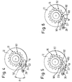
- a belt retractor according to an embodiment of the invention is shown.
- a belt spool 12 is rotatably mounted in a housing 10, onto which the belt webbing, not shown here, is wound.
- On both sides of the belt reel 12 there is an annular locking toothing 16 with locking teeth 161 which is formed in one piece with the belt reel 12 as a die-cast part.
- One pawl 18, which is pivotably mounted in the housing 10, is provided for engagement in the associated locking toothing 16 of the belt reel 12.
- the two pawls 18 are coupled to one another via a connecting rod, not shown here, which enables a coordinated pivoting movement of the two pawls 18.
- Each pawl 18 is provided with a control tooth 181 and two pawl teeth 182 and 183 and has a control link 22, on which a control cam 24 of a conventional and therefore not described vehicle and webbing sensitive automatic locking device 26 engages.
- the control movement of the pawls 18 into the locking teeth 16 is controlled via the automatic blocking mechanism 26 and the control cams 24.
- the control cam 24 slides along the control link 22 of the pawl 18 so that it is moved into the locking teeth 16 of the belt spool 12.
- each pawl 18 is provided with a bearing pin 28 which is mounted in a housing part, not shown here.
- the control link 22 of each pawl 18 has on one side of its apex 220 a control section 221, on which the distance from the center of the locking toothing 16 increases in the rest position of the pawl 18, and on the other side an outlet section 222 on which this distance is smaller becomes.
- the extent of the outlet section 222 measured in the circumferential direction of the locking toothing 16 is approximately twice that of the control section 221.
- the control tooth 181 of the locking pawl 18 can be pivoted into the region of the locking teeth 161 of the locking toothing 16 via the control section 221.
- the pawl 18 experiences a radial stroke, which is dimensioned such that the pawl 18 by the control cam 24 until the first contact of the control tooth 181 with a tooth flank of a locking tooth 161 of the locking toothing 16 and at most insignificantly beyond is pivoted.
- the pivoting movement of the pawls 18 thus initially takes place on the basis of the relative movement between the control cam 24 and the control link 22, the control cam 24 pivoting the pawl 18 up to the apex 220 of the control link 22 in the region of the locking toothing 16.
- the control cam 24 then moves along the outlet section 222 of the control link 22 until the next locking tooth 161 of the locking toothing 16 grips the control tooth 181 when the belt reel 12 rotates.
- a torque is exerted on the pawl 18 as a result of the rotation of the belt reel 12, by means of which the pawl 18 is forced to pivot until the pawl teeth 182, 183 engage with the locking teeth 16 .
- the peculiarity of the belt retractor according to the invention is clear from a consideration of the so-called pre-control angle.
- the pre-control angle is the angle of rotation of the belt spool 12 from the beginning of the pivoting of the pawl 18 from its rest position to its first contact with the next tooth of the locking toothing 16 opposite it.
- the pre-control angle is determined statically, that is to say with slow rotation of the belt spool, so that inertia effects do not occur appear.
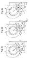
- FIGS. 2a to 3c shows the process of actuating the pawl 18 in its blocking position with a minimum possible pilot angle.
- the minimum possible pre-control angle is the one at which it is ensured that the control tooth 181 of the pawl 18 hits the tooth gap which is already rotating on the belt spool 12 which is already rotating before the next tooth.
- FIG. 2a shows the starting position of the pawl 18.
- the angles of rotation included in the definition of the pilot control angle are related to an axis A parallel to the bottom of the housing 10. In the starting position shown in FIG. 2a, the angle between the axis A and a line running through the axis of rotation of the belt reel 12 and the apex of its tooth opposite the control pawl 181 is 34 °.
- the angle of rotation between the axis A and a line running through the axis of rotation of the belt reel 12 and through the control cam 24 is 27 °.
- the angle of rotation between the apex of the control tooth 181 and the opposite apex of the tooth on the belt reel 12 is approximately 1 °. This angle must not be smaller so that the control tooth 181 can still dive into the tooth gap preceding the adjacent tooth.
- the angle of the tooth of the locking toothing 16 with which the control tooth 181 first came into contact with the axis A is now 45 °, and the angle of the control cam 24 is 38 °.
- the pre-control angle ⁇ is the angle of rotation of the belt reel between the positions shown in Figs. 2a and 2b, i.e. the difference between the angles 41 ° and 34 °, equal to 7 °.
- the angle of rotation of the tooth of the locking toothing relative to the axis A is 41 °, and the angle of the control cam 24 is 51 °.
- the angles are 45 ° and 55 °.
- the values for the minimum and for the maximum pre-control angle can deviate from the values given above, depending on the geometry of the toothings.
- the maximum possible value of the pre-control angle is important, since a large value can compensate for the losses that occur during the dynamic control process, which can easily reach 10 ° to 14 ° with a belt retractor with belt tensioner.
- a pre-control angle range is easily obtained which is more than twice the possible value for a conventional belt retractor, in which the entire control stroke is effected by the control link of the pawl.
- the pre-control angle can therefore be chosen to be large enough that it is sufficient even for very high belt spool rotational accelerations and is nevertheless within the permissible tolerance range at which the pawl does not jam.
Landscapes
- Engineering & Computer Science (AREA)
- Mechanical Engineering (AREA)
- Automotive Seat Belt Assembly (AREA)
- Shaping By String And By Release Of Stress In Plastics And The Like (AREA)
Applications Claiming Priority (2)
| Application Number | Priority Date | Filing Date | Title |
|---|---|---|---|
| DE4327135A DE4327135A1 (de) | 1993-08-12 | 1993-08-12 | Gurtaufroller für Sicherheitsgurt-Rückhaltesysteme in Fahrzeugen |
| DE4327135 | 1993-08-12 |
Publications (3)
| Publication Number | Publication Date |
|---|---|
| EP0638467A2 true EP0638467A2 (fr) | 1995-02-15 |
| EP0638467A3 EP0638467A3 (fr) | 1997-09-10 |
| EP0638467B1 EP0638467B1 (fr) | 2000-02-02 |
Family
ID=6495054
Family Applications (1)
| Application Number | Title | Priority Date | Filing Date |
|---|---|---|---|
| EP94110815A Expired - Lifetime EP0638467B1 (fr) | 1993-08-12 | 1994-07-12 | Enrouleur de ceinture pour systèmes de retenue par ceinture de sécurité dans les véhicules |
Country Status (6)
| Country | Link |
|---|---|
| US (1) | US5593105A (fr) |
| EP (1) | EP0638467B1 (fr) |
| JP (1) | JP2634379B2 (fr) |
| KR (1) | KR0142284B1 (fr) |
| DE (2) | DE4327135A1 (fr) |
| ES (1) | ES2072233T3 (fr) |
Cited By (3)
| Publication number | Priority date | Publication date | Assignee | Title |
|---|---|---|---|---|
| EP0865975A1 (fr) * | 1997-03-18 | 1998-09-23 | TRW Occupant Restraint Systems GmbH & Co. KG | Rétracteur pour ceinture de sécurité de véhicule automobile |
| EP0952048A1 (fr) * | 1998-04-23 | 1999-10-27 | TRW Occupant Restraint Systems GmbH & Co. KG | Enrouleur de ceinture de sécurité pour un système de retenue |
| GB2347900A (en) * | 1999-03-15 | 2000-09-20 | Breed Automotive Tech | Seat Belt Retractor |
Families Citing this family (13)
| Publication number | Priority date | Publication date | Assignee | Title |
|---|---|---|---|---|
| DE19680286B4 (de) * | 1995-03-16 | 2004-11-11 | Nsk Ltd. | Gurtaufwickelvorrichtung mit einer Notfallsperreinrichtung |
| DE19524162A1 (de) * | 1995-07-03 | 1997-01-09 | Trw Repa Gmbh | Gurtaufroller für einen Sicherheitsgurt |
| US5899298A (en) * | 1997-03-19 | 1999-05-04 | Crouse, Jr.; Benjamin F. | Safety harness for stairs |
| US6632443B2 (en) | 2000-02-23 | 2003-10-14 | National Research Council Of Canada | Water-soluble compositions of bioactive lipophilic compounds |
| US6045826A (en) * | 1999-04-02 | 2000-04-04 | National Research Council Of Canada | Water-soluble compositions of bioactive lipophilic compounds |
| US20080070981A1 (en) * | 2000-02-23 | 2008-03-20 | Henryk Borowy-Borowski | Water-soluble compositions of bioactive lipophilic compounds |
| JP3709300B2 (ja) * | 1999-04-16 | 2005-10-26 | 株式会社東海理化電機製作所 | ウエビング巻取装置 |
| KR100323845B1 (ko) * | 1999-12-09 | 2002-02-07 | 이승복 | 차량용 좌석벨트 리트랙터 |
| GB2379910B (en) * | 2001-09-19 | 2003-09-24 | Breed Automotive Tech | Seat belt retractor |
| DE10160071B4 (de) * | 2001-12-06 | 2007-01-18 | Daimlerchrysler Ag | Verfahren zur Ansteuerung eines reversiblen Gurtstraffers |
| GB2451835B (en) * | 2007-08-13 | 2009-07-01 | Checkmate Safety Llp | Fall arrest block |
| DE102015109444B4 (de) * | 2015-06-12 | 2018-08-02 | Bornack Gmbh & Co. Kg | Seilsicherungsvorrichtung |
| US9751495B2 (en) | 2015-08-21 | 2017-09-05 | Carleton Life Support Systems, Inc. | Reel lock having multiple tooth dog |
Family Cites Families (14)
| Publication number | Priority date | Publication date | Assignee | Title |
|---|---|---|---|---|
| JPS5024933A (fr) * | 1974-02-04 | 1975-03-17 | ||
| US4083512A (en) * | 1976-04-02 | 1978-04-11 | The Firestone Tire & Rubber Company | Independent redundant clutchless retractor |
| DE3011283C2 (de) * | 1980-03-24 | 1986-11-27 | TRW Repa GmbH, 7077 Alfdorf | Sicherheitsgurtaufroller |
| AU1001683A (en) * | 1982-01-26 | 1983-08-04 | Britax (Wingard) Limited | Safety belt inertia reel |
| JPS5988165A (ja) * | 1982-11-11 | 1984-05-22 | タカタ株式会社 | 安全ベルト巻取装置 |
| JPS60169791A (ja) * | 1984-02-14 | 1985-09-03 | Sanyo Electric Co Ltd | 計算機付世界時計 |
| DE8405545U1 (de) * | 1984-02-21 | 1984-06-20 | Autoliv GmbH, 2200 Elmshorn | Vorrichtung zum selbsttaetigen aufrollen eines fahrzeugsicherheitsgurtes |
| US4726541A (en) * | 1985-04-10 | 1988-02-23 | Nsk Warner K.K. | Emergency locking retractor |
| GB2216775C (en) * | 1988-03-29 | 1994-11-25 | Trw Repa Gmbh | A belt retractor for a motor vehicle safety belt restraining system |
| US4895317A (en) * | 1988-10-31 | 1990-01-23 | Trw Vehicle Safety Systems Inc. | Electrically actuatable locking mechanism for a seat belt retractor |
| JP3192198B2 (ja) * | 1991-04-11 | 2001-07-23 | タカタ株式会社 | シートベルトリトラクタ |
| JP3153309B2 (ja) * | 1992-01-30 | 2001-04-09 | タカタ株式会社 | シートベルトリトラクタ |
| JP3093852B2 (ja) * | 1992-01-30 | 2000-10-03 | タカタ株式会社 | シートベルトリトラクタ |
| JPH0572612U (ja) * | 1992-03-09 | 1993-10-05 | 株式会社東海理化電機製作所 | ウエビング巻取装置 |
-
1993
- 1993-08-12 DE DE4327135A patent/DE4327135A1/de not_active Withdrawn
-
1994
- 1994-07-12 ES ES94110815T patent/ES2072233T3/es not_active Expired - Lifetime
- 1994-07-12 EP EP94110815A patent/EP0638467B1/fr not_active Expired - Lifetime
- 1994-07-12 DE DE59409117T patent/DE59409117D1/de not_active Expired - Lifetime
- 1994-08-02 US US08/284,180 patent/US5593105A/en not_active Expired - Lifetime
- 1994-08-10 KR KR1019940019677A patent/KR0142284B1/ko not_active Expired - Fee Related
- 1994-08-11 JP JP6189547A patent/JP2634379B2/ja not_active Expired - Lifetime
Cited By (6)
| Publication number | Priority date | Publication date | Assignee | Title |
|---|---|---|---|---|
| EP0865975A1 (fr) * | 1997-03-18 | 1998-09-23 | TRW Occupant Restraint Systems GmbH & Co. KG | Rétracteur pour ceinture de sécurité de véhicule automobile |
| US5931402A (en) * | 1997-03-18 | 1999-08-03 | Trw Occupant Restraint Systems Gmbh | Belt winder for a vehicle safety belt |
| EP0952048A1 (fr) * | 1998-04-23 | 1999-10-27 | TRW Occupant Restraint Systems GmbH & Co. KG | Enrouleur de ceinture de sécurité pour un système de retenue |
| US6241173B1 (en) | 1998-04-23 | 2001-06-05 | Trw Occupant Restraint Systems Gmbh & Co. Kg | Belt retractor for a safety belt restraint system |
| GB2347900A (en) * | 1999-03-15 | 2000-09-20 | Breed Automotive Tech | Seat Belt Retractor |
| US6267315B1 (en) | 1999-03-15 | 2001-07-31 | Breed Automotive Technology, Inc. | Seat belt retractor |
Also Published As
| Publication number | Publication date |
|---|---|
| ES2072233T3 (es) | 2000-07-16 |
| DE4327135A1 (de) | 1995-02-16 |
| ES2072233T1 (es) | 1995-07-16 |
| EP0638467A3 (fr) | 1997-09-10 |
| DE59409117D1 (de) | 2000-03-09 |
| JP2634379B2 (ja) | 1997-07-23 |
| JPH07144608A (ja) | 1995-06-06 |
| KR950005636A (ko) | 1995-03-20 |
| KR0142284B1 (ko) | 1998-06-01 |
| US5593105A (en) | 1997-01-14 |
| EP0638467B1 (fr) | 2000-02-02 |
Similar Documents
| Publication | Publication Date | Title |
|---|---|---|
| EP0638467B1 (fr) | Enrouleur de ceinture pour systèmes de retenue par ceinture de sécurité dans les véhicules | |
| DE29816280U1 (de) | Vorrichtung zur Kraftbegrenzung | |
| EP0737606B1 (fr) | Enrouleur de ceinture pour un système de ceinture de sécurité de véhicule | |
| DE19615589A1 (de) | Kabelspannvorrichtung | |
| DE10119753A1 (de) | Gurtstraffer | |
| DE102024106570A1 (de) | Sicherheitsgurtaufroller | |
| DE3636847C2 (fr) | ||
| WO2012041443A1 (fr) | Enrouleur de ceinture à blocage automatique | |
| DE2419937A1 (de) | Aufwickelvorrichtung | |
| DE102004015825B4 (de) | Gurtaufroller für einen Fahrzeug-Sicherheitsgurt | |
| DE102011101965B4 (de) | Gurtaufroller mit Steuerverzahnung | |
| DE3810701A1 (de) | Rueckstrammvorrichtung | |
| DE3049564A1 (de) | Aufrollvorrichtung fuer sicherheitsgurte | |
| DE9217298U1 (de) | Sitzgurt-Vorspanneinrichtung | |
| EP0460009B1 (fr) | Enrouleur automatique de ceinture de securite | |
| DE2754155C2 (de) | Aufrollvorrichtung für Sicherheitsgurte | |
| DE3627715A1 (de) | Sicherheitsgurtaufroller | |
| DE3421960A1 (de) | Gurtaufroll- und sperrmechanismus | |
| DE2824864A1 (de) | Gurtaufrollschnellsperrautomat | |
| WO2014139658A1 (fr) | Enrouleur de ceinture de sécurité | |
| DE3908666A1 (de) | Gurtaufroller | |
| EP0318720B1 (fr) | Dispositif automatique de réglage de la longueur d'un câble Bowden | |
| DE19508620C2 (de) | Sicherheitsgurt-Rückhaltesystem mit Auslösesicherung für mechanischen Sensor | |
| DE10357812B4 (de) | Gurtspule für einen Sicherheitsgurtaufroller | |
| DE4232237B4 (de) | Gurtaufroller |
Legal Events
| Date | Code | Title | Description |
|---|---|---|---|
| PUAI | Public reference made under article 153(3) epc to a published international application that has entered the european phase |
Free format text: ORIGINAL CODE: 0009012 |
|
| AK | Designated contracting states |
Kind code of ref document: A2 Designated state(s): DE ES FR GB IT SE |
|
| GBC | Gb: translation of claims filed (gb section 78(7)/1977) | ||
| ITCL | It: translation for ep claims filed |
Representative=s name: DR. ING. A. RACHELI & C. |
|
| EL | Fr: translation of claims filed | ||
| REG | Reference to a national code |
Ref country code: ES Ref legal event code: BA2A Ref document number: 2072233 Country of ref document: ES Kind code of ref document: T1 |
|
| RAP1 | Party data changed (applicant data changed or rights of an application transferred) |
Owner name: TRW OCCUPANT RESTRAINT SYSTEMS GMBH |
|
| PUAL | Search report despatched |
Free format text: ORIGINAL CODE: 0009013 |
|
| AK | Designated contracting states |
Kind code of ref document: A3 Designated state(s): DE ES FR GB IT SE |
|
| 17P | Request for examination filed |
Effective date: 19971222 |
|
| RAP1 | Party data changed (applicant data changed or rights of an application transferred) |
Owner name: TRW OCCUPANT RESTRAINT SYSTEMS GMBH & CO. KG |
|
| GRAG | Despatch of communication of intention to grant |
Free format text: ORIGINAL CODE: EPIDOS AGRA |
|
| GRAG | Despatch of communication of intention to grant |
Free format text: ORIGINAL CODE: EPIDOS AGRA |
|
| GRAH | Despatch of communication of intention to grant a patent |
Free format text: ORIGINAL CODE: EPIDOS IGRA |
|
| 17Q | First examination report despatched |
Effective date: 19990702 |
|
| GRAH | Despatch of communication of intention to grant a patent |
Free format text: ORIGINAL CODE: EPIDOS IGRA |
|
| GRAA | (expected) grant |
Free format text: ORIGINAL CODE: 0009210 |
|
| AK | Designated contracting states |
Kind code of ref document: B1 Designated state(s): DE ES FR GB IT SE |
|
| REF | Corresponds to: |
Ref document number: 59409117 Country of ref document: DE Date of ref document: 20000309 |
|
| ITF | It: translation for a ep patent filed | ||
| ET | Fr: translation filed | ||
| PG25 | Lapsed in a contracting state [announced via postgrant information from national office to epo] |
Ref country code: SE Free format text: LAPSE BECAUSE OF FAILURE TO SUBMIT A TRANSLATION OF THE DESCRIPTION OR TO PAY THE FEE WITHIN THE PRESCRIBED TIME-LIMIT Effective date: 20000502 |
|
| GBT | Gb: translation of ep patent filed (gb section 77(6)(a)/1977) |
Effective date: 20000614 |
|
| REG | Reference to a national code |
Ref country code: ES Ref legal event code: FG2A Ref document number: 2072233 Country of ref document: ES Kind code of ref document: T3 |
|
| PLBE | No opposition filed within time limit |
Free format text: ORIGINAL CODE: 0009261 |
|
| STAA | Information on the status of an ep patent application or granted ep patent |
Free format text: STATUS: NO OPPOSITION FILED WITHIN TIME LIMIT |
|
| 26N | No opposition filed | ||
| PGFP | Annual fee paid to national office [announced via postgrant information from national office to epo] |
Ref country code: GB Payment date: 20010614 Year of fee payment: 8 |
|
| REG | Reference to a national code |
Ref country code: GB Ref legal event code: IF02 |
|
| PG25 | Lapsed in a contracting state [announced via postgrant information from national office to epo] |
Ref country code: GB Free format text: LAPSE BECAUSE OF NON-PAYMENT OF DUE FEES Effective date: 20020712 |
|
| GBPC | Gb: european patent ceased through non-payment of renewal fee |
Effective date: 20020712 |
|
| PGFP | Annual fee paid to national office [announced via postgrant information from national office to epo] |
Ref country code: FR Payment date: 20030702 Year of fee payment: 10 |
|
| PG25 | Lapsed in a contracting state [announced via postgrant information from national office to epo] |
Ref country code: FR Free format text: LAPSE BECAUSE OF NON-PAYMENT OF DUE FEES Effective date: 20050331 |
|
| REG | Reference to a national code |
Ref country code: FR Ref legal event code: ST |
|
| PGFP | Annual fee paid to national office [announced via postgrant information from national office to epo] |
Ref country code: ES Payment date: 20060717 Year of fee payment: 13 |
|
| REG | Reference to a national code |
Ref country code: ES Ref legal event code: FD2A Effective date: 20070713 |
|
| PGFP | Annual fee paid to national office [announced via postgrant information from national office to epo] |
Ref country code: IT Payment date: 20080717 Year of fee payment: 15 |
|
| PG25 | Lapsed in a contracting state [announced via postgrant information from national office to epo] |
Ref country code: ES Free format text: LAPSE BECAUSE OF NON-PAYMENT OF DUE FEES Effective date: 20070713 |
|
| PG25 | Lapsed in a contracting state [announced via postgrant information from national office to epo] |
Ref country code: IT Free format text: LAPSE BECAUSE OF NON-PAYMENT OF DUE FEES Effective date: 20090712 |
|
| PGFP | Annual fee paid to national office [announced via postgrant information from national office to epo] |
Ref country code: DE Payment date: 20110731 Year of fee payment: 18 |
|
| PG25 | Lapsed in a contracting state [announced via postgrant information from national office to epo] |
Ref country code: DE Free format text: LAPSE BECAUSE OF NON-PAYMENT OF DUE FEES Effective date: 20130201 |
|
| REG | Reference to a national code |
Ref country code: DE Ref legal event code: R119 Ref document number: 59409117 Country of ref document: DE Effective date: 20130201 |