EP0638467B1 - Enrouleur de ceinture pour systèmes de retenue par ceinture de sécurité dans les véhicules - Google Patents
Enrouleur de ceinture pour systèmes de retenue par ceinture de sécurité dans les véhicules Download PDFInfo
- Publication number
- EP0638467B1 EP0638467B1 EP94110815A EP94110815A EP0638467B1 EP 0638467 B1 EP0638467 B1 EP 0638467B1 EP 94110815 A EP94110815 A EP 94110815A EP 94110815 A EP94110815 A EP 94110815A EP 0638467 B1 EP0638467 B1 EP 0638467B1
- Authority
- EP
- European Patent Office
- Prior art keywords
- locking
- control
- pawl
- tooth
- belt
- Prior art date
- Legal status (The legal status is an assumption and is not a legal conclusion. Google has not performed a legal analysis and makes no representation as to the accuracy of the status listed.)
- Expired - Lifetime
Links
- 230000000903 blocking effect Effects 0.000 claims description 11
- 230000000452 restraining effect Effects 0.000 claims 1
- 230000033001 locomotion Effects 0.000 description 9
- 230000001133 acceleration Effects 0.000 description 5
- 238000000034 method Methods 0.000 description 4
- 238000004519 manufacturing process Methods 0.000 description 2
- 230000001360 synchronised effect Effects 0.000 description 2
- 240000003517 Elaeocarpus dentatus Species 0.000 description 1
- 230000004913 activation Effects 0.000 description 1
- 230000000694 effects Effects 0.000 description 1
- 230000029305 taxis Effects 0.000 description 1
- 230000001960 triggered effect Effects 0.000 description 1
Images


Classifications
-
- B—PERFORMING OPERATIONS; TRANSPORTING
- B60—VEHICLES IN GENERAL
- B60R—VEHICLES, VEHICLE FITTINGS, OR VEHICLE PARTS, NOT OTHERWISE PROVIDED FOR
- B60R22/00—Safety belts or body harnesses in vehicles
- B60R22/34—Belt retractors, e.g. reels
- B60R22/36—Belt retractors, e.g. reels self-locking in an emergency
Definitions
- the invention relates to a belt retractor for seat belt restraint systems in vehicles with an automatic locking system that is sensitive to vehicle and webbing for the belt reel, which is rotatably mounted in the housing, on which an annular Locking toothing is attached, and with a swivel on the housing stored pawl, which has at least two ratchet teeth and from their rest position by one acting on a control link of the pawl Control cam of the automatic locking system synchronous with the belt spool rotation is pivotable for engagement in the locking teeth.
- a pawl is synchronized with the belt spool rotation for engagement in a locking toothing of the belt reel by a pivoted on the control link of the pawl control cam. So that the pawl teeth of the pawl do not fall on the control movement Have the apex of the locking teeth of the locking teeth of the belt reel the locking teeth and the pawl at the beginning of the control movement one predetermined position to each other.
- the automatic blocking is triggered by a control lever in the pawl the locking teeth pivoted. It comes with fast control processes due to the inertia of the controls involved in the control process to delay the control movement of the pawl. This tax loss gets bigger with increasing acceleration of the belt spool rotation. Extremely high accelerations of the belt spool rotation and thus large control losses occur, for example, after a belt tensioning process increased reverse acceleration of the webbing.
- This tax loss is partially offset by the fact that the pivoting movement the pawl leads the belt spool rotation.
- the angle of rotation of the belt reel for pivoting the pawl from it The rest position until the ratchet tooth is first touched is the pre-control angle Are defined.
- the maximum size of the pilot angle is limited because if the pilot angle is too large, the pawl jams in the Blocking position occurs. If the pilot angle is too large and If there are no high acceleration accelerations, activation can the locking mechanism one pawl tooth of the pawl with the closest The back of a ratchet tooth comes into contact before the control cam has reached the top of the control link on the pawl.
- the invention has for its object a belt retractor of the beginning specified type to create, due to structurally simple measures a large pre-control angle range is permissible, so that it is also relatively large Manufacturing tolerances no individual checking or correction of the pre-control angle condition.
- the invention is based on the knowledge that by dividing the Control stroke in a first section determined by the control link and a second, by the control tooth of the pawl when it hits on the locking toothing of the belt reel, a certain pre-control angle range is determined by the section without risk of jamming the pawl in their Blocking position is possible.
- the pilot angle is between 0.7 and 1.2 times the Pitch of the ratchet teeth.
- control tooth is opposite to the extended line retreating through the apex and the center of the locking teeth Has toothbrush. This allows the control tooth to be low-loss on a tooth flank the locking teeth slide.
- a belt retractor according to an embodiment of the Invention shown.
- a belt spool 12 is rotatable in a housing 10 stored, is wound onto the webbing, not shown here.
- One pawl each pivotally mounted in the housing 10 18 is for engagement in the associated locking teeth 16 of the belt reel 12 provided.
- the two pawls 18 are not shown here Link rod coupled together, creating a coordinated Pivotal movement of the two pawls 18 is made possible.
- each pawl 18 with a control tooth 181 and two pawl teeth 182 and 183 and has a control link 22 on which a control cam 24 a conventional and therefore not described vehicle and webbing sensitive Automatic blocking 26 attacks. Via the automatic blocking 26 and the control cam 24, the control movement of the pawls 18 in the Lock teeth 16 controlled. The control cam 24 slides along the Control link 22 of the pawl 18 so that this into the locking toothing 16th the belt spool 12 is moved.
- Each pawl is 18 for the pivoting movement provided with a journal 28, which in a not shown here Housing part is stored.
- the control link 22 of each pawl 18 has on one side of it Vertex 220 a control section 221, on which in the rest position Pawl 18 the distance from the center of the locking teeth 16 increases, and on the other side an outlet section 222 on which this distance Is getting smaller.
- the measured in the circumferential direction of the locking toothing 16 Extension of the outlet section 222 is approximately twice as large as that of the Control section 221.
- Via control section 221 is the control tooth 181 of the pawl 18 in the area of the locking teeth 161 of the locking teeth 16 pivotable.
- the pawl 18 experiences a radial stroke, which is dimensioned so that the Pawl 18 through the control cam 24 until the control tooth touches for the first time 181 with a tooth flank of a locking tooth 161 of the locking teeth 16 and is pivoted beyond at most insignificantly.
- the pivotal movement of the pawls 18 is therefore initially due to the Relative movement between the control cam 24 and the control link 22, wherein the control cam 24, the pawl 18 up to the apex 220 of the control link 22 pivoted into the area of the locking teeth 16. Subsequently the control cam 24 moves along the outlet section 222 of the control link 22 until, when the belt reel 12 rotates, the next locking tooth 161 Locking teeth 16 holds the control tooth 181. After the first touch of the control tooth 181 with a tooth flank of the locking tooth 161 is on the pawl 18th as a result of the rotation of the belt reel 12, a torque is exerted by the Pawl 18 pivoting until the positive engagement of the Pawl teeth 182, 183 is forced with the locking teeth 16.
- the peculiarity of the belt retractor according to the invention is illustrated of the so-called pre-steering angle clearly.
- the pre-steering angle is the angle of rotation of the belt reel 12 from the beginning of the pivoting of the pawl 18 from their rest position until their first contact with the next, their opposite tooth of the locking toothing 16.
- the pilot angle is determined statically, so with slow rotation of the belt spool, so that Mass inertia effects do not appear.
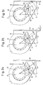
- FIGS. 2a to 3c illustrate the control process the pawl 18 in its blocking position with minimal possible Pre-steering angle shows.
- the minimum possible pre-control angle is the one which ensures that the control tooth 181 of the pawl 18 still before the next tooth on the already rotating belt reel 12 in it previous tooth gap meets.
- Fig. 2a shows the starting position of the pawl 18.
- the angle of rotation included in the definition of the pre-control angle are related to an axis A parallel to the bottom of the housing 10. In the The starting position shown in FIG. 2a is the angle between the axis A. and one through the axis of rotation of the belt reel 12 and the apex of its Control pawl 181 opposite tooth running line 34 °.
- the angle of rotation between the axis A and one through the axis of rotation of the belt reel 12 and line through the control cam 24 is 27 °.
- the angle of rotation between the apex of the control tooth 181 and the opposite one The apex of the tooth on the belt reel 12 is approximately 1 °. This may be smaller Angle should not be so that the control tooth 181 is still in the adjacent tooth previous tooth gap can immerse.
- the pawl 18 is in a form-fitting manner Engagement with the locking teeth 16 on the belt spool 12.
- the angle of that tooth of the locking toothing again related to the axis A. 16, with which the control tooth 181 first came into contact now 45 °, and the angle of the control cam 24 is 38 °.
- the pre-steering angle ⁇ is the angle of rotation of the belt spool between those shown in Figs. 2a and 2b Positions, i.e. the difference between the angles 41 ° and 34 °, so equal to 7 °.
- the belt retractor according to the invention results in a simple manner Pre-steering angle range that is more than twice the possible value a conventional belt retractor, in which the entire control stroke is caused by the control link of the pawl.
- the pre-steering angle can therefore be chosen so large that it can also be used for very high belt spins sufficient and yet within the permissible tolerance range is where the pawl does not jam.
Landscapes
- Engineering & Computer Science (AREA)
- Mechanical Engineering (AREA)
- Automotive Seat Belt Assembly (AREA)
- Shaping By String And By Release Of Stress In Plastics And The Like (AREA)
Claims (8)
- Enrouleur de ceinture pour systèmes de retenue à ceintures de sécurité dans des véhicules, comprenant un moyen de blocage automatique (26) sensible au comportement du véhicule et à celui de la sangle de ceinture et destiné à la bobine de ceinture (12) montée en rotation dans le boítier (10) et pourvue d'une denture d'arrêt annulaire (16), et comprenant un cliquet d'arrêt (18) qui est monté pivotant sur le boítier (10), qui comporte au moins deux dents d'arrêt (181, 182, 183) et qui, sous l'action d'un ergot de commande (24) faisant partie du moyen de blocage automatique (26) et agissant sur une coulisse de commande (22) du cliquet d'arrêt (18), peut, à partir de sa position de repos, pivoter de manière synchrone avec la rotation de la bobine de ceinture pour s'engager dans la denture d'arrêt (16), caractérisé en ce quea) la dent d'arrêt qui arrive la première en contact avec la denture d'arrêt (16) est configurée en dent de commande (181) ;b) la coulisse de commande (22) possède une course radiale qui est calculée pour que, sous l'action de l'ergot de commande (24), le cliquet d'arrêt (18) pivote jusqu'au premier contact de la dent de commande (181) avec un flanc de dent de la denture d'arrêt (16) et tout au plus dans une proportion insignifiante au-delà ; etc) après le premier contact de la dent de commande (181) avec un flanc de dent de la denture d'arrêt (16), la rotation de la bobine de ceinture exerce sur le cliquet d'arrêt (18) un couple qui contraint ledit cliquet d'arrêt (18) à pivoter jusqu'à une position bloquée définie par un engrènement par complémentarité de formes des dents d'arrêt (181, 182, 183) avec la denture d'arrêt (16).
- Enrouleur de ceinture selon la revendication 1, caractérisé en ce que l'angle de préengagement (α) défini par la valeur de l'angle de rotation de la bobine de ceinture (12) correspondant au pivotement du cliquet d'arrêt (18) de sa position de repos jusqu'au premier contact de la dent de commande (181) avec un flanc de dent de la denture d'arrêt (16) et déterminé statiquement est du même ordre de grandeur que le pas (β) de la denture d'arrêt (16).
- Enrouleur de ceinture selon la revendication 2, caractérisé en ce que l'angle de préengagement (α) déterminé statiquement est compris entre 0,7 et 1,2 fois le pas (β) de la denture d'arrêt (16).
- Enrouleur de ceinture selon une des revendications précédentes, caractérisé en ce que, dans la zone du premier contact de la dent de commande (181) avec un flanc de dent de la denture d'arrêt (161), l'angle (γ) entre la perpendiculaire au flanc de dent et une ligne passant par le point de premier contact et par l'axe de pivotement du cliquet d'arrêt (18) est compris entre au moins 30° et de préférence environ 38°.
- Enrouleur de ceinture selon la revendication 4, caractérisé en ce que la dent de commande (181) comporte une face en retrait par rapport au prolongement d'une ligne passant par son sommet et par le centre de la denture d'arrêt (16).
- Enrouleur de ceinture selon une des revendications précédentes, caractérisé en ce que, en plus de la dent de commande (181), le cliquet d'arrêt (18) comporte deux autres dents d'arrêt (182, 183).
- Enrouleur de ceinture selon une des revendications précédentes, dans lequel la coulisse de commande comporte une portion d'engagement (221), où, lorsque le cliquet d'arrêt (18) est en position de repos, sa distance par rapport au centre de la denture d'arrêt (16) augmente, et une portion de sortie (222) qui s'y raccorde et où cette distance est moindre, caractérisé en ce que, lorsque le cliquet d'arrêt (18) est en position de repos, la portion d'engagement (221) forme un angle (δ) d'environ 60° avec une ligne qui passe par le centre de la denture d'arrêt (16) et par l'axe de l'ergot de commande (24).
- Enrouleur de ceinture selon la revendication 7, caractérisé en ce que la longueur de la portion de sortie (222) mesurée dans la direction circonférentielle de la denture d'arrêt (16) est environ deux fois supérieure à celle de la portion d'engagement (221).
Applications Claiming Priority (2)
| Application Number | Priority Date | Filing Date | Title |
|---|---|---|---|
| DE4327135 | 1993-08-12 | ||
| DE4327135A DE4327135A1 (de) | 1993-08-12 | 1993-08-12 | Gurtaufroller für Sicherheitsgurt-Rückhaltesysteme in Fahrzeugen |
Publications (3)
| Publication Number | Publication Date |
|---|---|
| EP0638467A2 EP0638467A2 (fr) | 1995-02-15 |
| EP0638467A3 EP0638467A3 (fr) | 1997-09-10 |
| EP0638467B1 true EP0638467B1 (fr) | 2000-02-02 |
Family
ID=6495054
Family Applications (1)
| Application Number | Title | Priority Date | Filing Date |
|---|---|---|---|
| EP94110815A Expired - Lifetime EP0638467B1 (fr) | 1993-08-12 | 1994-07-12 | Enrouleur de ceinture pour systèmes de retenue par ceinture de sécurité dans les véhicules |
Country Status (6)
| Country | Link |
|---|---|
| US (1) | US5593105A (fr) |
| EP (1) | EP0638467B1 (fr) |
| JP (1) | JP2634379B2 (fr) |
| KR (1) | KR0142284B1 (fr) |
| DE (2) | DE4327135A1 (fr) |
| ES (1) | ES2072233T3 (fr) |
Families Citing this family (16)
| Publication number | Priority date | Publication date | Assignee | Title |
|---|---|---|---|---|
| DE19680286B4 (de) * | 1995-03-16 | 2004-11-11 | Nsk Ltd. | Gurtaufwickelvorrichtung mit einer Notfallsperreinrichtung |
| DE19524162A1 (de) * | 1995-07-03 | 1997-01-09 | Trw Repa Gmbh | Gurtaufroller für einen Sicherheitsgurt |
| DE29704974U1 (de) * | 1997-03-18 | 1997-07-17 | Trw Occupant Restraint Systems Gmbh, 73551 Alfdorf | Gurtaufroller für einen Fahrzeug-Sicherheitsgurt |
| US5899298A (en) * | 1997-03-19 | 1999-05-04 | Crouse, Jr.; Benjamin F. | Safety harness for stairs |
| DE29807433U1 (de) * | 1998-04-23 | 1998-08-20 | TRW Occupant Restraint Systems GmbH & Co. KG, 73553 Alfdorf | Gurtaufroller für ein Sicherheitsgurt-Rückhaltesystem |
| GB2347900A (en) * | 1999-03-15 | 2000-09-20 | Breed Automotive Tech | Seat Belt Retractor |
| US20080070981A1 (en) * | 2000-02-23 | 2008-03-20 | Henryk Borowy-Borowski | Water-soluble compositions of bioactive lipophilic compounds |
| US6045826A (en) * | 1999-04-02 | 2000-04-04 | National Research Council Of Canada | Water-soluble compositions of bioactive lipophilic compounds |
| US6632443B2 (en) | 2000-02-23 | 2003-10-14 | National Research Council Of Canada | Water-soluble compositions of bioactive lipophilic compounds |
| JP3709300B2 (ja) * | 1999-04-16 | 2005-10-26 | 株式会社東海理化電機製作所 | ウエビング巻取装置 |
| KR100323845B1 (ko) * | 1999-12-09 | 2002-02-07 | 이승복 | 차량용 좌석벨트 리트랙터 |
| GB2379910B (en) * | 2001-09-19 | 2003-09-24 | Breed Automotive Tech | Seat belt retractor |
| DE10160071B4 (de) * | 2001-12-06 | 2007-01-18 | Daimlerchrysler Ag | Verfahren zur Ansteuerung eines reversiblen Gurtstraffers |
| GB2451835B (en) * | 2007-08-13 | 2009-07-01 | Checkmate Safety Llp | Fall arrest block |
| DE102015109444B4 (de) * | 2015-06-12 | 2018-08-02 | Bornack Gmbh & Co. Kg | Seilsicherungsvorrichtung |
| US9751495B2 (en) | 2015-08-21 | 2017-09-05 | Carleton Life Support Systems, Inc. | Reel lock having multiple tooth dog |
Family Cites Families (14)
| Publication number | Priority date | Publication date | Assignee | Title |
|---|---|---|---|---|
| JPS5024933A (fr) * | 1974-02-04 | 1975-03-17 | ||
| US4083512A (en) * | 1976-04-02 | 1978-04-11 | The Firestone Tire & Rubber Company | Independent redundant clutchless retractor |
| DE3011283C2 (de) * | 1980-03-24 | 1986-11-27 | TRW Repa GmbH, 7077 Alfdorf | Sicherheitsgurtaufroller |
| AU1001683A (en) * | 1982-01-26 | 1983-08-04 | Britax (Wingard) Limited | Safety belt inertia reel |
| JPS5988165A (ja) * | 1982-11-11 | 1984-05-22 | タカタ株式会社 | 安全ベルト巻取装置 |
| JPS60169791A (ja) * | 1984-02-14 | 1985-09-03 | Sanyo Electric Co Ltd | 計算機付世界時計 |
| DE8405545U1 (de) * | 1984-02-21 | 1984-06-20 | Autoliv GmbH, 2200 Elmshorn | Vorrichtung zum selbsttaetigen aufrollen eines fahrzeugsicherheitsgurtes |
| US4726541A (en) * | 1985-04-10 | 1988-02-23 | Nsk Warner K.K. | Emergency locking retractor |
| GB2216775C (en) * | 1988-03-29 | 1994-11-25 | Trw Repa Gmbh | A belt retractor for a motor vehicle safety belt restraining system |
| US4895317A (en) * | 1988-10-31 | 1990-01-23 | Trw Vehicle Safety Systems Inc. | Electrically actuatable locking mechanism for a seat belt retractor |
| JP3192198B2 (ja) * | 1991-04-11 | 2001-07-23 | タカタ株式会社 | シートベルトリトラクタ |
| JP3153309B2 (ja) * | 1992-01-30 | 2001-04-09 | タカタ株式会社 | シートベルトリトラクタ |
| JP3093852B2 (ja) * | 1992-01-30 | 2000-10-03 | タカタ株式会社 | シートベルトリトラクタ |
| JPH0572612U (ja) * | 1992-03-09 | 1993-10-05 | 株式会社東海理化電機製作所 | ウエビング巻取装置 |
-
1993
- 1993-08-12 DE DE4327135A patent/DE4327135A1/de not_active Withdrawn
-
1994
- 1994-07-12 ES ES94110815T patent/ES2072233T3/es not_active Expired - Lifetime
- 1994-07-12 DE DE59409117T patent/DE59409117D1/de not_active Expired - Lifetime
- 1994-07-12 EP EP94110815A patent/EP0638467B1/fr not_active Expired - Lifetime
- 1994-08-02 US US08/284,180 patent/US5593105A/en not_active Expired - Lifetime
- 1994-08-10 KR KR1019940019677A patent/KR0142284B1/ko not_active Expired - Fee Related
- 1994-08-11 JP JP6189547A patent/JP2634379B2/ja not_active Expired - Lifetime
Also Published As
| Publication number | Publication date |
|---|---|
| EP0638467A2 (fr) | 1995-02-15 |
| EP0638467A3 (fr) | 1997-09-10 |
| ES2072233T1 (es) | 1995-07-16 |
| ES2072233T3 (es) | 2000-07-16 |
| US5593105A (en) | 1997-01-14 |
| JPH07144608A (ja) | 1995-06-06 |
| DE59409117D1 (de) | 2000-03-09 |
| KR0142284B1 (ko) | 1998-06-01 |
| KR950005636A (ko) | 1995-03-20 |
| DE4327135A1 (de) | 1995-02-16 |
| JP2634379B2 (ja) | 1997-07-23 |
Similar Documents
| Publication | Publication Date | Title |
|---|---|---|
| EP0638467B1 (fr) | Enrouleur de ceinture pour systèmes de retenue par ceinture de sécurité dans les véhicules | |
| DE69608445T2 (de) | Sicherheitsgurtaufroller | |
| EP0737606B1 (fr) | Enrouleur de ceinture pour un système de ceinture de sécurité de véhicule | |
| DE29816280U1 (de) | Vorrichtung zur Kraftbegrenzung | |
| DE69209737T2 (de) | Gurtaufrollvorrichtung | |
| DE3715846A1 (de) | Sicherheitsgurtaufroller mit rueckstrammvorrichtung | |
| DE102024106570A1 (de) | Sicherheitsgurtaufroller | |
| DE3636847C2 (fr) | ||
| DE4311201C2 (de) | Sicherheitsgurtaufroller mit Klemmvorrichtung | |
| DE3810701A1 (de) | Rueckstrammvorrichtung | |
| DE3049564A1 (de) | Aufrollvorrichtung fuer sicherheitsgurte | |
| DE1954122A1 (de) | Automatische Sperrvorrichtung fuer einen Sicherheitsgurt | |
| EP0460009B1 (fr) | Enrouleur automatique de ceinture de securite | |
| DE3421960A1 (de) | Gurtaufroll- und sperrmechanismus | |
| DE2754155C2 (de) | Aufrollvorrichtung für Sicherheitsgurte | |
| WO2014139658A1 (fr) | Enrouleur de ceinture de sécurité | |
| DE3627715A1 (de) | Sicherheitsgurtaufroller | |
| DE3228882C2 (de) | Gurtaufroller für Sicherheitsgurte | |
| DE3248426C2 (fr) | ||
| DE3873878T2 (de) | Gurtband-aufroller. | |
| DE3908666A1 (de) | Gurtaufroller | |
| EP0391982B1 (fr) | Enrouleurs de ceintures de securite dans des vehicules | |
| DE4232237B4 (de) | Gurtaufroller | |
| DE3303209C2 (fr) | ||
| DE19800456A1 (de) | Drosselventilvorrichtung eines Motors mit innerer Verbrennung |
Legal Events
| Date | Code | Title | Description |
|---|---|---|---|
| PUAI | Public reference made under article 153(3) epc to a published international application that has entered the european phase |
Free format text: ORIGINAL CODE: 0009012 |
|
| AK | Designated contracting states |
Kind code of ref document: A2 Designated state(s): DE ES FR GB IT SE |
|
| GBC | Gb: translation of claims filed (gb section 78(7)/1977) | ||
| ITCL | It: translation for ep claims filed |
Representative=s name: DR. ING. A. RACHELI & C. |
|
| EL | Fr: translation of claims filed | ||
| REG | Reference to a national code |
Ref country code: ES Ref legal event code: BA2A Ref document number: 2072233 Country of ref document: ES Kind code of ref document: T1 |
|
| RAP1 | Party data changed (applicant data changed or rights of an application transferred) |
Owner name: TRW OCCUPANT RESTRAINT SYSTEMS GMBH |
|
| PUAL | Search report despatched |
Free format text: ORIGINAL CODE: 0009013 |
|
| AK | Designated contracting states |
Kind code of ref document: A3 Designated state(s): DE ES FR GB IT SE |
|
| 17P | Request for examination filed |
Effective date: 19971222 |
|
| RAP1 | Party data changed (applicant data changed or rights of an application transferred) |
Owner name: TRW OCCUPANT RESTRAINT SYSTEMS GMBH & CO. KG |
|
| GRAG | Despatch of communication of intention to grant |
Free format text: ORIGINAL CODE: EPIDOS AGRA |
|
| GRAG | Despatch of communication of intention to grant |
Free format text: ORIGINAL CODE: EPIDOS AGRA |
|
| GRAH | Despatch of communication of intention to grant a patent |
Free format text: ORIGINAL CODE: EPIDOS IGRA |
|
| 17Q | First examination report despatched |
Effective date: 19990702 |
|
| GRAH | Despatch of communication of intention to grant a patent |
Free format text: ORIGINAL CODE: EPIDOS IGRA |
|
| GRAA | (expected) grant |
Free format text: ORIGINAL CODE: 0009210 |
|
| AK | Designated contracting states |
Kind code of ref document: B1 Designated state(s): DE ES FR GB IT SE |
|
| REF | Corresponds to: |
Ref document number: 59409117 Country of ref document: DE Date of ref document: 20000309 |
|
| ITF | It: translation for a ep patent filed | ||
| ET | Fr: translation filed | ||
| PG25 | Lapsed in a contracting state [announced via postgrant information from national office to epo] |
Ref country code: SE Free format text: LAPSE BECAUSE OF FAILURE TO SUBMIT A TRANSLATION OF THE DESCRIPTION OR TO PAY THE FEE WITHIN THE PRESCRIBED TIME-LIMIT Effective date: 20000502 |
|
| GBT | Gb: translation of ep patent filed (gb section 77(6)(a)/1977) |
Effective date: 20000614 |
|
| REG | Reference to a national code |
Ref country code: ES Ref legal event code: FG2A Ref document number: 2072233 Country of ref document: ES Kind code of ref document: T3 |
|
| PLBE | No opposition filed within time limit |
Free format text: ORIGINAL CODE: 0009261 |
|
| STAA | Information on the status of an ep patent application or granted ep patent |
Free format text: STATUS: NO OPPOSITION FILED WITHIN TIME LIMIT |
|
| 26N | No opposition filed | ||
| PGFP | Annual fee paid to national office [announced via postgrant information from national office to epo] |
Ref country code: GB Payment date: 20010614 Year of fee payment: 8 |
|
| REG | Reference to a national code |
Ref country code: GB Ref legal event code: IF02 |
|
| PG25 | Lapsed in a contracting state [announced via postgrant information from national office to epo] |
Ref country code: GB Free format text: LAPSE BECAUSE OF NON-PAYMENT OF DUE FEES Effective date: 20020712 |
|
| GBPC | Gb: european patent ceased through non-payment of renewal fee |
Effective date: 20020712 |
|
| PGFP | Annual fee paid to national office [announced via postgrant information from national office to epo] |
Ref country code: FR Payment date: 20030702 Year of fee payment: 10 |
|
| PG25 | Lapsed in a contracting state [announced via postgrant information from national office to epo] |
Ref country code: FR Free format text: LAPSE BECAUSE OF NON-PAYMENT OF DUE FEES Effective date: 20050331 |
|
| REG | Reference to a national code |
Ref country code: FR Ref legal event code: ST |
|
| PGFP | Annual fee paid to national office [announced via postgrant information from national office to epo] |
Ref country code: ES Payment date: 20060717 Year of fee payment: 13 |
|
| REG | Reference to a national code |
Ref country code: ES Ref legal event code: FD2A Effective date: 20070713 |
|
| PGFP | Annual fee paid to national office [announced via postgrant information from national office to epo] |
Ref country code: IT Payment date: 20080717 Year of fee payment: 15 |
|
| PG25 | Lapsed in a contracting state [announced via postgrant information from national office to epo] |
Ref country code: ES Free format text: LAPSE BECAUSE OF NON-PAYMENT OF DUE FEES Effective date: 20070713 |
|
| PG25 | Lapsed in a contracting state [announced via postgrant information from national office to epo] |
Ref country code: IT Free format text: LAPSE BECAUSE OF NON-PAYMENT OF DUE FEES Effective date: 20090712 |
|
| PGFP | Annual fee paid to national office [announced via postgrant information from national office to epo] |
Ref country code: DE Payment date: 20110731 Year of fee payment: 18 |
|
| PG25 | Lapsed in a contracting state [announced via postgrant information from national office to epo] |
Ref country code: DE Free format text: LAPSE BECAUSE OF NON-PAYMENT OF DUE FEES Effective date: 20130201 |
|
| REG | Reference to a national code |
Ref country code: DE Ref legal event code: R119 Ref document number: 59409117 Country of ref document: DE Effective date: 20130201 |