EP0638467B1 - Belt retractor for safety belt restraint systems in vehicles - Google Patents
Belt retractor for safety belt restraint systems in vehicles Download PDFInfo
- Publication number
- EP0638467B1 EP0638467B1 EP94110815A EP94110815A EP0638467B1 EP 0638467 B1 EP0638467 B1 EP 0638467B1 EP 94110815 A EP94110815 A EP 94110815A EP 94110815 A EP94110815 A EP 94110815A EP 0638467 B1 EP0638467 B1 EP 0638467B1
- Authority
- EP
- European Patent Office
- Prior art keywords
- locking
- control
- pawl
- tooth
- belt
- Prior art date
- Legal status (The legal status is an assumption and is not a legal conclusion. Google has not performed a legal analysis and makes no representation as to the accuracy of the status listed.)
- Expired - Lifetime
Links
Images


Classifications
-
- B—PERFORMING OPERATIONS; TRANSPORTING
- B60—VEHICLES IN GENERAL
- B60R—VEHICLES, VEHICLE FITTINGS, OR VEHICLE PARTS, NOT OTHERWISE PROVIDED FOR
- B60R22/00—Safety belts or body harnesses in vehicles
- B60R22/34—Belt retractors, e.g. reels
- B60R22/36—Belt retractors, e.g. reels self-locking in an emergency
Definitions
- the invention relates to a belt retractor for seat belt restraint systems in vehicles with an automatic locking system that is sensitive to vehicle and webbing for the belt reel, which is rotatably mounted in the housing, on which an annular Locking toothing is attached, and with a swivel on the housing stored pawl, which has at least two ratchet teeth and from their rest position by one acting on a control link of the pawl Control cam of the automatic locking system synchronous with the belt spool rotation is pivotable for engagement in the locking teeth.
- a pawl is synchronized with the belt spool rotation for engagement in a locking toothing of the belt reel by a pivoted on the control link of the pawl control cam. So that the pawl teeth of the pawl do not fall on the control movement Have the apex of the locking teeth of the locking teeth of the belt reel the locking teeth and the pawl at the beginning of the control movement one predetermined position to each other.
- the automatic blocking is triggered by a control lever in the pawl the locking teeth pivoted. It comes with fast control processes due to the inertia of the controls involved in the control process to delay the control movement of the pawl. This tax loss gets bigger with increasing acceleration of the belt spool rotation. Extremely high accelerations of the belt spool rotation and thus large control losses occur, for example, after a belt tensioning process increased reverse acceleration of the webbing.
- This tax loss is partially offset by the fact that the pivoting movement the pawl leads the belt spool rotation.
- the angle of rotation of the belt reel for pivoting the pawl from it The rest position until the ratchet tooth is first touched is the pre-control angle Are defined.
- the maximum size of the pilot angle is limited because if the pilot angle is too large, the pawl jams in the Blocking position occurs. If the pilot angle is too large and If there are no high acceleration accelerations, activation can the locking mechanism one pawl tooth of the pawl with the closest The back of a ratchet tooth comes into contact before the control cam has reached the top of the control link on the pawl.
- the invention has for its object a belt retractor of the beginning specified type to create, due to structurally simple measures a large pre-control angle range is permissible, so that it is also relatively large Manufacturing tolerances no individual checking or correction of the pre-control angle condition.
- the invention is based on the knowledge that by dividing the Control stroke in a first section determined by the control link and a second, by the control tooth of the pawl when it hits on the locking toothing of the belt reel, a certain pre-control angle range is determined by the section without risk of jamming the pawl in their Blocking position is possible.
- the pilot angle is between 0.7 and 1.2 times the Pitch of the ratchet teeth.
- control tooth is opposite to the extended line retreating through the apex and the center of the locking teeth Has toothbrush. This allows the control tooth to be low-loss on a tooth flank the locking teeth slide.
- a belt retractor according to an embodiment of the Invention shown.
- a belt spool 12 is rotatable in a housing 10 stored, is wound onto the webbing, not shown here.
- One pawl each pivotally mounted in the housing 10 18 is for engagement in the associated locking teeth 16 of the belt reel 12 provided.
- the two pawls 18 are not shown here Link rod coupled together, creating a coordinated Pivotal movement of the two pawls 18 is made possible.
- each pawl 18 with a control tooth 181 and two pawl teeth 182 and 183 and has a control link 22 on which a control cam 24 a conventional and therefore not described vehicle and webbing sensitive Automatic blocking 26 attacks. Via the automatic blocking 26 and the control cam 24, the control movement of the pawls 18 in the Lock teeth 16 controlled. The control cam 24 slides along the Control link 22 of the pawl 18 so that this into the locking toothing 16th the belt spool 12 is moved.
- Each pawl is 18 for the pivoting movement provided with a journal 28, which in a not shown here Housing part is stored.
- the control link 22 of each pawl 18 has on one side of it Vertex 220 a control section 221, on which in the rest position Pawl 18 the distance from the center of the locking teeth 16 increases, and on the other side an outlet section 222 on which this distance Is getting smaller.
- the measured in the circumferential direction of the locking toothing 16 Extension of the outlet section 222 is approximately twice as large as that of the Control section 221.
- Via control section 221 is the control tooth 181 of the pawl 18 in the area of the locking teeth 161 of the locking teeth 16 pivotable.
- the pawl 18 experiences a radial stroke, which is dimensioned so that the Pawl 18 through the control cam 24 until the control tooth touches for the first time 181 with a tooth flank of a locking tooth 161 of the locking teeth 16 and is pivoted beyond at most insignificantly.
- the pivotal movement of the pawls 18 is therefore initially due to the Relative movement between the control cam 24 and the control link 22, wherein the control cam 24, the pawl 18 up to the apex 220 of the control link 22 pivoted into the area of the locking teeth 16. Subsequently the control cam 24 moves along the outlet section 222 of the control link 22 until, when the belt reel 12 rotates, the next locking tooth 161 Locking teeth 16 holds the control tooth 181. After the first touch of the control tooth 181 with a tooth flank of the locking tooth 161 is on the pawl 18th as a result of the rotation of the belt reel 12, a torque is exerted by the Pawl 18 pivoting until the positive engagement of the Pawl teeth 182, 183 is forced with the locking teeth 16.
- the peculiarity of the belt retractor according to the invention is illustrated of the so-called pre-steering angle clearly.
- the pre-steering angle is the angle of rotation of the belt reel 12 from the beginning of the pivoting of the pawl 18 from their rest position until their first contact with the next, their opposite tooth of the locking toothing 16.
- the pilot angle is determined statically, so with slow rotation of the belt spool, so that Mass inertia effects do not appear.
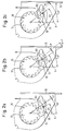
- FIGS. 2a to 3c illustrate the control process the pawl 18 in its blocking position with minimal possible Pre-steering angle shows.
- the minimum possible pre-control angle is the one which ensures that the control tooth 181 of the pawl 18 still before the next tooth on the already rotating belt reel 12 in it previous tooth gap meets.
- Fig. 2a shows the starting position of the pawl 18.
- the angle of rotation included in the definition of the pre-control angle are related to an axis A parallel to the bottom of the housing 10. In the The starting position shown in FIG. 2a is the angle between the axis A. and one through the axis of rotation of the belt reel 12 and the apex of its Control pawl 181 opposite tooth running line 34 °.
- the angle of rotation between the axis A and one through the axis of rotation of the belt reel 12 and line through the control cam 24 is 27 °.
- the angle of rotation between the apex of the control tooth 181 and the opposite one The apex of the tooth on the belt reel 12 is approximately 1 °. This may be smaller Angle should not be so that the control tooth 181 is still in the adjacent tooth previous tooth gap can immerse.
- the pawl 18 is in a form-fitting manner Engagement with the locking teeth 16 on the belt spool 12.
- the angle of that tooth of the locking toothing again related to the axis A. 16, with which the control tooth 181 first came into contact now 45 °, and the angle of the control cam 24 is 38 °.
- the pre-steering angle ⁇ is the angle of rotation of the belt spool between those shown in Figs. 2a and 2b Positions, i.e. the difference between the angles 41 ° and 34 °, so equal to 7 °.
- the belt retractor according to the invention results in a simple manner Pre-steering angle range that is more than twice the possible value a conventional belt retractor, in which the entire control stroke is caused by the control link of the pawl.
- the pre-steering angle can therefore be chosen so large that it can also be used for very high belt spins sufficient and yet within the permissible tolerance range is where the pawl does not jam.
Description
Die Erfindung betrifft einen Gurtaufroller für Sicherheitsgurt-Rückhaltesysteme in Fahrzeugen, mit einer fahrzeug- und gurtbandsensitiven Blockierautomatik für die im Gehäuse drehbar gelagerte Gurtspule, an der eine ringförmige Sperrverzahnung angebracht ist, und mit einer am Gehäuse schwenkbar gelagerten Sperrlinke, die mindestens zwei Klinkenzähne aufweist und aus ihrer Ruhestellung durch einen an einer Steuerkulisse der Sperrklinke angreifenden Steuernocken der Blockierautomatik synchron mit der Gurtspulendrehung zum Eingriff in die Sperrverzahnung verschwenkbar ist.The invention relates to a belt retractor for seat belt restraint systems in vehicles with an automatic locking system that is sensitive to vehicle and webbing for the belt reel, which is rotatably mounted in the housing, on which an annular Locking toothing is attached, and with a swivel on the housing stored pawl, which has at least two ratchet teeth and from their rest position by one acting on a control link of the pawl Control cam of the automatic locking system synchronous with the belt spool rotation is pivotable for engagement in the locking teeth.
Ein solcher Gurtaufroller ist aus EP-A- 152 909 bekannt.Such a belt retractor is known from EP-A-152 909.
Bei bekannten Gurtaufrollern wird eine Sperrklinke synchron mit der Gurtspulendrehung zum Eingriff in eine Sperrverzahnung der Gurtspule durch einen an der Steuerkulisse der Sperrklinke angreifenden Steuernocken verschwenkt. Damit die Klinkenzähne der Sperrklinke bei der Einsteuerbewegung nicht auf den Scheitel der Sperrzähne der Sperrverzahnung der Gurtspule auftreffen, haben die Sperrverzahnung und die Sperrklinke zu Beginn der Einsteuerbewegung eine vorbestimmte Stellung zueinander. Bei der fahrzeug- oder gurtbandsensitiven Auslösung der Blockierautomatik wird über einen Steuerhebel die Sperrklinke in die Sperrverzahnung verschwenkt. Bei schnellen Einsteuervorgängen kommt es aufgrund der Massenträgheit der am Einsteuervorgang beteiligten Steuerelemente zu einer Verzögerung der Einsteuerbewegung der Sperrklinke. Dieser Einsteuerverlust wird mit wachsender Beschleunigung der Gurtspulendrehung größer. Äußerst hohe Beschleunigungen der Gurtspulendrehung und somit große Einsteuerverluste treten beispielsweise nach einem Gurtstraffervorgang durch eine erhöhte Umkehrbeschleunigung des Gurtbands auf.In known belt retractors, a pawl is synchronized with the belt spool rotation for engagement in a locking toothing of the belt reel by a pivoted on the control link of the pawl control cam. So that the pawl teeth of the pawl do not fall on the control movement Have the apex of the locking teeth of the locking teeth of the belt reel the locking teeth and the pawl at the beginning of the control movement one predetermined position to each other. For vehicle or belt sensitive The automatic blocking is triggered by a control lever in the pawl the locking teeth pivoted. It comes with fast control processes due to the inertia of the controls involved in the control process to delay the control movement of the pawl. This tax loss gets bigger with increasing acceleration of the belt spool rotation. Extremely high accelerations of the belt spool rotation and thus large control losses occur, for example, after a belt tensioning process increased reverse acceleration of the webbing.
Dieser Einsteuerverlust wird zum Teil dadurch ausgeglichen, daß die Verschwenkbewegung der Sperrklinke in Bezug auf die Gurtspulendrehung vorauseilt. Der Drehwinkel der Gurtspule für die Verschwenkung der Sperrklinke aus ihrer Ruhestellung bis zur Erstberührung des Sperrzahns ist als Voreinsteuerwinkel definiert. Die maximale Größe des Voreinsteuerwinkels ist aber begrenzt, weil bei zu großem Voreinsteuerwinkel ein Verklemmen der Sperrklinke in der Blockierstellung eintritt. Ist nämlich der Voreinsteuerwinkel zu groß und treten keine hohen Einsteuerbeschleunigungen auf, so kann bei einer Aktivierung der Blockierautomatik ein Klinkenzahn der Sperrklinke mit dem nächstliegenden Zahnrücken eines Sperrzahns in Berührung kommen, bevor der Steuernocken den Scheitel der Steuerkulisse an der Sperrklinke erreicht hat.This tax loss is partially offset by the fact that the pivoting movement the pawl leads the belt spool rotation. The angle of rotation of the belt reel for pivoting the pawl from it The rest position until the ratchet tooth is first touched is the pre-control angle Are defined. The maximum size of the pilot angle is limited because if the pilot angle is too large, the pawl jams in the Blocking position occurs. If the pilot angle is too large and If there are no high acceleration accelerations, activation can the locking mechanism one pawl tooth of the pawl with the closest The back of a ratchet tooth comes into contact before the control cam has reached the top of the control link on the pawl.
Andererseits sind bei der Dimensionierung des Voreinsteuerwinkels aurch Fertigungstoleranzen zu berücksichtigen, so daß nur ein schmaler Winkelbereich in Frage kommt.On the other hand, when dimensioning the pilot control angle, Manufacturing tolerances to be taken into account, so that only a narrow angular range in Question is coming.
Aufgrund der oben angegebenen Einflüsse ist es notwendig, daß die Einsteuerung der Sperrklinke bei jedem Gurtaufroller einzeln überprüft und eventuell eine Korrektur des Voreinsteuerwinkels vorgenommen wird.Due to the influences mentioned above, it is necessary that the control the pawl is checked individually for each belt retractor and possibly one Correction of the pilot angle is made.
Der Erfindung liegt die Aufgabe zugrunde, einen Gurtaufroller der eingangs angegebenen Art zu schaffen, bei dem aufgrund konstruktiv einfacher Maßnahmen ein großer Voreinsteuerwinkelbereich zulässig ist, so daß auch relativ große Fertigungstoleranzen keine Einzelüberprüfung oder Korrektur des Voreinsteuerwinkels bedingen.The invention has for its object a belt retractor of the beginning specified type to create, due to structurally simple measures a large pre-control angle range is permissible, so that it is also relatively large Manufacturing tolerances no individual checking or correction of the pre-control angle condition.
Diese Aufgabe wird bei dem eingangs angegebenen Gurtaufroller erfindungsgemäß
dadurch gelöst, daß
Der Erfindung liegt die Erkenntnis zugrunde, daß durch eine Aufteilung des Einsteuerhubes in einem ersten, durch die Steuerkulisse bestimmten Abschnitt und einen zweiten, durch den Steuerzahn der Sperrklinke bei dessen Auftreffen auf der Sperrverzahnung der Gurtspule bestimmten Abschnitt ein größerer Voreinsteuerwinkelbereich ohne Gefahr des Verklemmens der Sperrklinke in ihrer Blockierstellung möglich ist.The invention is based on the knowledge that by dividing the Control stroke in a first section determined by the control link and a second, by the control tooth of the pawl when it hits on the locking toothing of the belt reel, a certain pre-control angle range is determined by the section without risk of jamming the pawl in their Blocking position is possible.
Gemäß einer vorteilhaften Ausführungsform der Erfindung ist der durch die Größe des Drehwinkels der Gurtspule für die Verschwenkung der Sperrklinke aus ihrer Ruhestellung bis zur Erstberührung des Steuerzahns mit einer Zahnflanke der Sperrverzahnung definierte, statisch ermittelte Voreinsteuerwinkel von der gleichen Größenordnung wie das Teilungsmaß der Sperrverzahnung. Insbesondere beträgt der Voreinsteuerwinkel zwischen dem 0,7 und dem 1,2 -fachen des Teilungsmaßes der Sperrverzahnung.According to an advantageous embodiment of the invention, the size the angle of rotation of the belt reel for pivoting the pawl from it Rest position up to the first contact of the control tooth with a tooth flank of the Locking teeth defined, statically determined pre-control angle from the same size as the pitch of the locking toothing. In particular the pilot angle is between 0.7 and 1.2 times the Pitch of the ratchet teeth.
Um ein ausreichendes Drehmoment zu gewährleisten, durch das der Sperrklinke eine Verschwenkung bis zum formschlüssigen Eingriff der Klinkenzähne mit der Sperrverzahnung aufgezwungen wird, beträgt im Bereich der Erstberührung des Steuerzahns mit einer Zahnflanke der Sperrverzahnung der Winkel zwischen dem Lot auf der Zahnflanke und einer Linie durch den Ort der Erstberührung und die Schwenkachse der Sperrklinke mindestens 30° und vorzugsweise etwa 38°.To ensure sufficient torque by the pawl a pivoting until the latch teeth engage positively with the Locking gear is forced in the area of the first touch of the Control tooth with a tooth flank of the locking toothing the angle between the Lot on the tooth flank and a line through the place of the first contact and the Pivot axis of the pawl at least 30 ° and preferably about 38 °.
Zweckmäßig ist es, wenn der Steuerzahn eine gegenüber der verlängerten Linie durch den Scheitel und den Mittelpunkt der Sperrverzahnung zurückweichende Zahnbrust aufweist. Dadurch kann der Steuerzahn verlustarm auf einer Zahnflanke der Sperrverzahnung gleiten. It is useful if the control tooth is opposite to the extended line retreating through the apex and the center of the locking teeth Has toothbrush. This allows the control tooth to be low-loss on a tooth flank the locking teeth slide.
Eine Übertragung großer Kräfte bei Blockierung der Gurtspule durch die in die Sperrverzahnung eingreifende Sperrklinke wird dadurch gewährleistet, daß die Sperrklinke außer dem Steuerzahn zwei weitere Klinkenzähne aufweist.A transfer of large forces when the belt spool is blocked by the in the Locking pawl engaging pawl is ensured that the Pawl has two further pawl teeth in addition to the control tooth.
Für einen optimalen Voreinsteuerwinkelbereich ist es von Vorteil, wenn in der Ruhestellung der Sperrklinke der Einsteuerabschnitt der Steuerkulisse mit einer Linie durch den Mittelpunkt der Sperrverzahnung auf die Achse des Steuernockens einen Winkel von etwa 60° bildet. Insbesondere ist es günstig, wenn die in Umfangsrichtung der Sperrverzahnung gemessene Erstreckung des Auslaufabschnitts etwa doppelt so groß ist wie die des Einsteuerabschnitts der Steuerkulisse.For an optimal pre-control angle range, it is advantageous if in the Rest position of the pawl of the control section of the control link with a Line through the center of the locking teeth on the axis of the control cam forms an angle of about 60 °. In particular, it is advantageous if the extent of the outlet section measured in the circumferential direction of the locking toothing is approximately twice as large as that of the control section of the Control backdrop.
Weitere Merkmale und Vorteile der Erfindung ergeben sich aus der folgenden Beschreibung einer Ausführungsform und aus der Zeichnung, auf die Bezug genommen wird. Es zeigen:
- Fig. 1
- eine Seiten-Teilschnittansicht eines Gurtaufrollers gemäß einer Ausführungsform der Erfindung; und
- Fig. 2a bis 3c
- Skizzen zur Veranschaulichung der Bedeutung des Voreinsteuerwinkels bei einem Gurtaufroller;
- Fig. 4 bis 6
- die Sperrverzahnung und die Sperrklinke des Gurtaufrollers von Fig. 1 in verschiedenen Einsteuerstellungen.
- Fig. 1
- a partial side sectional view of a belt retractor according to an embodiment of the invention; and
- 2a to 3c
- Sketches to illustrate the importance of the pre-control angle in a belt retractor;
- 4 to 6
- the locking teeth and the pawl of the belt retractor of Fig. 1 in different control positions.
In den Fig. 1 bis 6 ist ein Gurtaufroller gemäß einer Ausführungsform der
Erfindung dargestellt. In einem Gehäuse 10 ist eine Gurtspule 12 drehbar
gelagert, auf die hier nicht dargestelltes Gurtband aufgewickelt wird. An
beiden Seiten der Gurtspule 12 ist eine ringförmige Sperrverzahnung 16 mit
Sperrzähnen 161 vorgesehen, die mit der Gurtspule 12 einstückig als Druckgußteil
ausgebildet ist. Je eine schwenkbar im Gehäuse 10 gelagerte Sperrklinke
18 ist zum Eingriff in die zugehörige Sperrverzahnung 16 der Gurtspule
12 vorgesehen. Die beiden Sperrklinken 18 sind über eine hier nicht dargestellte
Verbindungsstange miteinander gekoppelt, wodurch eine koordinierte
Verschwenkbewegung der beiden Sperrklinken 18 ermöglicht wird. Weiterhin ist
jede Sperrklinke 18 mit einem Steuerzahn 181 und zwei Klinkenzähnen 182 und
183 versehen und weist eine Steuerkulisse 22 auf, an der ein Steuernocken 24
einer herkömmlichen und daher nicht näher beschriebenen fahrzeug- und gurtbandsensitiven
Blockierautomatik 26 angreift. Über die Blockierautomatik 26
und den Steuernocken 24 wird die Einsteuerbewegung der Sperrklinken 18 in die
Sperrverzahnungen 16 gesteuert. Der Steuernocken 24 gleitet entlang der
Steuerkulisse 22 der Sperrklinke 18, so daß diese in die Sperrverzahnung 16
der Gurtspule 12 bewegt wird. Für die Schwenkbewegung ist jede Sperrklinke 18
mit einem Lagerzapfen 28 versehen, der in einem hier nicht dargestellten
Gehäuseteil gelagert ist.1 to 6 is a belt retractor according to an embodiment of the
Invention shown. A
Die Steuerkulisse 22 jeder Sperrklinke 18 weist auf der einen Seite ihres
Scheitels 220 einen Einsteuerabschnitt 221, auf dem in der Ruhestellung der
Sperrklinke 18 der Abstand vom Mittelpunkt der Sperrverzahnung 16 zunimmt, und
auf der anderen Seite einen Auslaufabschnitt 222 auf, auf dem dieser Abstand
Kleiner wird. Die in Umfangsrichtung der Sperrverzahnung 16 gemessene
Erstreckung des Auslaufabschnitts 222 ist etwa doppelt so groß wie die des
Einsteuerabschnitts 221. Über den Einsteuerabschnitt 221 ist der Steuerzahn
181 der Sperrklinke 18 in den Bereich der Sperrzähne 161 der Sperrverzahnung
16 verschwenkbar. Über den an der Steuerkulisse 22 angreifenden Steuernocken
24 erfährt die Sperrklinke 18 einen radialen Hub, der so bemessen ist, daß die
Sperrklinke 18 durch den Steuernocken 24 bis zur Erstberührung des Steuerzahns
181 mit einer Zahnflanke eines Sperrzahns 161 der Sperrverzahnung 16 und
höchstens unwesentlich darüber hinaus verschwenkt wird.The
Die Verschwenkbewegung der Sperrklinken 18 erfolgt also zunächst aufgrund der
Relativbewegung zwischen dem Steuernocken 24 und der Steuerkulisse 22, wobei
der Steuernocken 24 die Sperrklinke 18 bis zu dem Scheitel 220 der Steuerkulisse
22 in den Bereich der Sperrverzahnung 16 verschwenkt. Anschließend
bewegt sich der Steuernocken 24 entlang dem Auslaufabschnitt 222 der Steuerkulisse
22, bis bei Drehung der Gurtspule 12 der nächste Sperrzahn 161 der
Sperrverzahnung 16 den Steuerzahn 181 faßt. Nach der Erstberührung des Steuerzahns
181 mit einer Zahnflanke des Sperrzahns 161 wird auf die Sperrklinke 18
als Folge der Drehung der Gurtspule 12 ein Drehmoment ausgeübt, durch das der
Sperrklinke 18 eine Verschwenkung bis zum formschlüssigen Eingriff der
Klinkenzähne 182, 183 mit der Sperrverzahnung 16 aufgezwungen wird. Erst mit
Erreichen der endgültigen Eingriffsstellung, also wenn die Klinkenzähne 182
und 183 nahezu am Zahngrund anliegen, kommen diese jeweils mit einer Zahnflanke
eines Sperrzahns 161 der Sperrverzahnung 16 in Anlage und blockieren
dadurch die Gurtspule 12 (Fig. 6).The pivotal movement of the
Die Besonderheit des erfindungsgemäßen Gurtaufrollers wird anhand einer Betrachtung
des Sogenannten Voreinsteuerwinkels deutlich. Der Voreinsteuerwinkel
ist der Drehwinkel der Gurtspule 12 vom Beginn der Verschwenkung der Sperrklinke
18 aus ihrer Ruhestellung bis zu ihrer Erstberührung mit dem nächsten,
ihr gegenüberliegenden Zahn der Sperrverzahnung 16. Der Voreinsteuerwinkel
wird statisch ermittelt, also bei langsamer Drehung der Gurtspule, so daß
Massenträgheitseffekte nicht in Erscheinung treten.The peculiarity of the belt retractor according to the invention is illustrated
of the so-called pre-steering angle clearly. The pre-steering angle
is the angle of rotation of the
Es wird nun auf die Figuren 2a bis 3c Bezug genommen, die den Vorgang der Einsteuerung
der Sperrklinke 18 in Ihrer Blockierstellung bei minimal möglichem
Voreinsteuerwinkel zeigt. Der minimal mögliche Voreinsteuerwinkel ist derjenige,
bei dem gewährleistet ist, daß der Steuerzahn 181 der Sperrklinke 18 noch
vor dem nächsten Zahn an der sich bereits drehenden Gurtspule 12 in die ihm
vorausgehende Zahnlücke trifft. Fig. 2a zeigt die Ausgangsstellung der Sperrklinke
18. Die in die Definition des Voreinsteuerwinkels eingehenden Drehwinkel
sind auf eine zum Boden des Gehäuses 10 parallele Achse A bezogen. In der
in Fig. 2a gezeigten Ausgangsstellung beträgt der Winkel zwischen der Achse A
und einer durch die Drehachse der Gurtspule 12 und den Scheitel ihres der
Steuerklinke 181 gegenüberliegenden Zahnes verlaufende Linie 34°. Der Drehwinkel
zwischen der Achse A und einer durch die Drehachse der Gurtspule 12 sowie
durch den Steuernocken 24 verlaufenden Linie beträgt 27°. Der Drehwinkel
zwischen dem Scheitel des Steuerzahns 181 und dem ihm gegenüberliegenden
Scheitel des Zahns an der Gurtspule 12 beträgt etwa 1°. Kleiner darf dieser
Winkel nicht sein, damit der Steuerzahn 181 noch in die dem benachbarten Zahn
vorausgehende Zahnlücke eintauchen kann.Reference is now made to FIGS. 2a to 3c, which illustrate the control process
the
In Fig. 2b ist diejenige Stellung gezeigt, in welcher der Steuerzahn 181 gerade
mit dem benachbarten Zahn an der Gurtspule 12 in Berührung kommt. Bezogen
auf die Achse A beträgt der Winkel des Zahns an der Gurtspule 12, der mit dem
Steuerzahn 181 in Berührung gekommen ist, 41°, und der Winkel des Steuernockens
24 beträgt 34°.2b shows the position in which the
Bei der in Fig. 2c gezeigten Blockierstellung ist die Sperrklinke 18 in formschlüssigen
Eingriff mit der Sperrverzahnung 16 an der Gurtspule 12 gelangt. In the blocking position shown in FIG. 2c, the
Der wieder auf die Achse A bezogene Winkel desjenigen Zahns der Sperrverzahnung
16, mit dem der Steuerzahn 181 zuerst in Berührung gekommen ist, beträgt
nunmehr 45°, und der Winkel des Steuernockens 24 beträgt 38°. Der Voreinsteuerwinkel
α ist der Drehwinkel der Gurtspule zwischen den in Fig. 2a und 2b gezeigten
Stellungen, d.h. die Differenz zwischen den Winkeln 41° und 34°, also
gleich 7°.The angle of that tooth of the locking toothing, again related to the axis A.
16, with which the
In den Figuren 3a bis 3c ist die Situation in analoger Weise für den maximal
möglichen Voreinsteuerwinkel dargestellt. Der Drehwinkel zwischen dem Scheitel
des Steuerzahns 181 und dem Steuernocken 24 beträgt 19°. Größer darf dieser
Winkel nicht sein, damit gewährleistet ist, daß der Rücken des Steuerzahns 181
nicht gegen den Scheitel des gegenüberliegenden Zahns der Sperrverzahnung 16
stößt, wodurch das Steuersystem blockiert würde. Bei einem Winkelwert von 19°
streift der Rücken des Steuerzahns 181 bereits an dem Zahnrücken des
gegenüberliegenden Zahns der Sperrverzahnung 16. Der auf die Achse A bezogene
Winkel desjenigen Zahns der Sperrverzahnung 16, an dem der Steuerzahn 181
angreift, beträgt in diesem Fall 17°, und der Winkel des Steuernockens 24
beträgt unverändert 27°.In Figures 3a to 3c, the situation is analogous for the maximum
possible pre-control angle is shown. The angle of rotation between the vertex
of the
Bei Erstberührung zwischen dem Steuerzahn 181 und dem betreffenden Zahn der
Sperrverzahnung 16 beträgt der auf die Achse A bezogene Drehwinkel des Zahns
der Sperrverzahnung 41°, und der Winkel des Steuernockens 24 beträgt 51°. Für
die in Fig. 3c gezeigte Blockierstellung betragen die Winkel 45° bzw. 55°. Es
ergibt sich ein maximal möglicher Voreinsteuerwinkel α von 41°-17°, also 24°.
Dieser Winkel stimmt mit dem Teilungsmaß der Sperrverzahnung 16 überein:
Da diese aus 15 Sperrzähnen besteht, errechnet sich das Teilungsmaß zu
360°: 15 = 24°.When first contact between the
Es versteht sich, daß die Werte für den minimalen und für den maximalen Voreinsteuerwinkel je nach Geometrie der Verzahnungen von den oben angegebenen Werten abweichen können. Von Bedeutung ist hauptsächlich der maximal mögliche Wert des Voreinsteuerwinkels, da durch einen großen Wert die beim dynamischen Einsteuervorgang auftretenden Verluste ausgeglichen werden können, die bei einem Gurtaufroller mit Gurtstraffer durchaus 10° bis 14° erreichen können.It is understood that the values for the minimum and for the maximum pilot angle depending on the geometry of the gearing from the above Values may differ. Most important is the maximum possible Value of the pre-control angle, since a large value means that the dynamic Taxes incurred losses that can be offset at a Belt retractors with belt tensioners can easily reach 10 ° to 14 °.
In Fig. 4 ist der Zustand dargestellt, in dem der Steuerzahn 181 gerade den
Sperrzahn 161 berührt. Der Abstand von dem Angriffspunkt, also dem Punkt, in
dem der Steuerzahn 181 auf der Zahnflanke des Sperrzahns 161 der Sperrverzahnung
16 liegt, zum Kopfkreisdurchmesser der Sperrverzahnung 16 beträgt
maximal etwa 1 mm. Der Fig. 4 ist deutlich zu entnehmen, daß sich der
Steuernocken 24, wenn der Steuerzahn 181 den Sperrzahn 161 der Sperrverzahnung
16 berührt, am Scheitel 220 der Steuerkulisse 22 befindet. Weiterhin
ist in Fig. 4 ein Winkel γ dargestellt, der zwischen dem Lot auf die
Zahnflanke des Sperrzahns 161 im Berührungspunkt mit dem Steuerzahn 181 und
einer Linie durch diesen Punkt und die Schwenkachse der Sperrklinke 18 gebildet
ist und vorzugsweise etwa 38° beträgt. Durch die Größe dieses Winkels γ
ist gewährleistet, daß auf die Sperrklinke 18 durch die Gurtspulendrehung ein
ausreichendes Drehmoment ausgeübt wird, um der die Sperrklinke 18 eine Zwangsverschwenkung
bis zum formschlüssigen Eingriff der Klinkenzähne 182, 183
mit der Sperrverzahnung 16 aufzugeben.4 shows the state in which the
In Fig. 5 hat der Steuernocken 24 bereits den Scheitel 220 überschritten, und
die Sperrklinke 18 wird nunmehr allein durch das sich ergebende, aufgezwungene,
eben erwähnte Drehmoment in die Eingriffsstellung verschwenkt. In
der Eingriffsstellung der Sperrklinke 18 in der Sperrverzahnung 16, siehe Fig.
6, besteht aufgrund der Verzahnungsgeometrie des Steuerzahns 181 sowie der
Klinkenzähne 182 und 183 einerseits und der Sperrzähne 161 andererseits ein
sicherer Formschluß.5, the
Mit dem erfindungsgemäßen Gurtaufroller ergibt sich auf einfache Weise ein Voreinsteuerwinkelbereich, der mehr als das Doppelte des möglichen Wertes bei einem herkömmlichen Gurtaufroller beträgt, bei dem der gesamte Einsteuerhub durch die Steuerkulisse der Sperrklinke bewirkt wird. Der Voreinsteuerwinkel kann daher so groß gewählt werden, das er auch für sehr hohe Gurtspulendrehbeschleunigungen ausreicht und dennoch innerhalb des zulässigen Toleranzbereiches liegt, bei dem keine Verklemmung der Sperrklinke eintritt.The belt retractor according to the invention results in a simple manner Pre-steering angle range that is more than twice the possible value a conventional belt retractor, in which the entire control stroke is caused by the control link of the pawl. The pre-steering angle can therefore be chosen so large that it can also be used for very high belt spins sufficient and yet within the permissible tolerance range is where the pawl does not jam.
Claims (8)
- A belt retractor for vehicular seat belt restraining systems, having a vehicle-sensitive and belt-sensitive automatic blocking mechanism (26) for the belt reel (12) rotatably mounted in the housing (10), on which a ring-shaped locking toothing (16) is provided, and further having a locking pawl (18) pivotably mounted on the housing (10) and having at least two paw] teeth (181, 182, 183) and which can be swivelled from its rest position to engage the locking toothing (16) in synchronism with rotation of the belt reel by means of a cam follower (24) of the automatic blocking mechanism (26) engaging a control cam (22) of the locking pawl (18), characterized in thata) one of the paw] teeth which first comes into contact with the locking toothing (16) is formed as a control tooth (181);b) the control cam (22) has a radial stroke which is dimensioned so that the locking pawl (18) is swivelled by the cam follower (24) up to first contact of the control tooth (181) with a tooth flank of the locking toothing (16) and insignificantly at the most beyond; andc) after first contact of the control tooth (181) with a tooth flank of the locking toothing (16) a torque is exerted on the locking pawl (18) by rotation of the belt reel, as a result of which the locking pawl (18) is forced to swivel up to its blocking position defined by positive interlock of the pawl teeth (181, 182, 183) with the locking toothing (16).
- The belt retractor as set forth in claim 1, characterized in that the prepositioning angle (α) statically established and defined by the amount of the angle of rotation of the belt reel (12) for swivelling the locking pawl (18) from its rest position up to first contact of the control tooth (181) with a tooth flank of the locking toothing (16) has the same magnitude as the pitch (β) of the locking toothing (16).
- The belt retractor as set forth in claim 2, characterized in that the statically established prepositioning angle (α) amounts to between 0.7 and 1.2 times the pitch (β) of the locking toothing (16).
- The belt retractor as set forth in any of the preceding claims, characterized in that the angle (γ) between the perpendicular to the tooth flank and a line passing through the location of first contact and the swivel axis of the locking pawl (18) amounts to at least 30° and preferably approx. 38° in the region of first contact of the control tooth (181) with a tooth flank of the locking toothing (161).
- The belt retractor as set forth in claim 4, characterized in that the control tooth (181) has a leading edge receding away from the extension of a line passing through its tip and the centre point of the locking toothing (16).
- The belt retractor as set forth in any of the preceding claims, characterized in that the locking pawl (18) has in addition to the control tooth (181) two further pawl teeth (182, 183).
- The belt retractor as set forth in any of the preceding claims, in which the control cam comprises a positioning section (221) at which in the rest position of the locking pawl (18) the distance away from the centre point of the locking toothing (16) increases, and an adjoining runout section (222) at which said distance away becomes smaller, characterized in that the positioning section (221) forms an angle (δ) of approx. 60° with a line passing through the centre point of the locking toothing (16) and the axis of the cam follower (24) in the rest position of the locking pawl (18).
- The belt retractor as set forth in claim 7, characterized in that the extension of the runout section (222) as measured in the circumferential direction of the locking toothing (16) is roughly twice as large as that of the positioning section (221).
Applications Claiming Priority (2)
| Application Number | Priority Date | Filing Date | Title |
|---|---|---|---|
| DE4327135 | 1993-08-12 | ||
| DE4327135A DE4327135A1 (en) | 1993-08-12 | 1993-08-12 | Belt retractor for seat belt restraint systems in vehicles |
Publications (3)
| Publication Number | Publication Date |
|---|---|
| EP0638467A2 EP0638467A2 (en) | 1995-02-15 |
| EP0638467A3 EP0638467A3 (en) | 1997-09-10 |
| EP0638467B1 true EP0638467B1 (en) | 2000-02-02 |
Family
ID=6495054
Family Applications (1)
| Application Number | Title | Priority Date | Filing Date |
|---|---|---|---|
| EP94110815A Expired - Lifetime EP0638467B1 (en) | 1993-08-12 | 1994-07-12 | Belt retractor for safety belt restraint systems in vehicles |
Country Status (6)
| Country | Link |
|---|---|
| US (1) | US5593105A (en) |
| EP (1) | EP0638467B1 (en) |
| JP (1) | JP2634379B2 (en) |
| KR (1) | KR0142284B1 (en) |
| DE (2) | DE4327135A1 (en) |
| ES (1) | ES2072233T3 (en) |
Families Citing this family (16)
| Publication number | Priority date | Publication date | Assignee | Title |
|---|---|---|---|---|
| DE19680286B4 (en) * | 1995-03-16 | 2004-11-11 | Nsk Ltd. | Retractor for vehicle seat belt - has pawls which slide relative to bobbin over set distance in direction in which take up shaft is rotated, and preventing bobbin from rotating in direction in which webbing is taken up |
| DE19524162A1 (en) * | 1995-07-03 | 1997-01-09 | Trw Repa Gmbh | Belt retractor for a seat belt |
| DE29704974U1 (en) * | 1997-03-18 | 1997-07-17 | Trw Repa Gmbh | Belt retractor for a vehicle seat belt |
| US5899298A (en) * | 1997-03-19 | 1999-05-04 | Crouse, Jr.; Benjamin F. | Safety harness for stairs |
| DE29807433U1 (en) | 1998-04-23 | 1998-08-20 | Trw Repa Gmbh | Belt retractor for a seat belt restraint system |
| GB2347900A (en) | 1999-03-15 | 2000-09-20 | Breed Automotive Tech | Seat Belt Retractor |
| US20080070981A1 (en) * | 2000-02-23 | 2008-03-20 | Henryk Borowy-Borowski | Water-soluble compositions of bioactive lipophilic compounds |
| US6632443B2 (en) | 2000-02-23 | 2003-10-14 | National Research Council Of Canada | Water-soluble compositions of bioactive lipophilic compounds |
| US6045826A (en) * | 1999-04-02 | 2000-04-04 | National Research Council Of Canada | Water-soluble compositions of bioactive lipophilic compounds |
| JP3709300B2 (en) * | 1999-04-16 | 2005-10-26 | 株式会社東海理化電機製作所 | Webbing take-up device |
| KR100323845B1 (en) * | 1999-12-09 | 2002-02-07 | 이승복 | Apparatus for retrading seat velt of vehicle |
| GB2379910B (en) * | 2001-09-19 | 2003-09-24 | Breed Automotive Tech | Seat belt retractor |
| DE10160071B4 (en) * | 2001-12-06 | 2007-01-18 | Daimlerchrysler Ag | Method for controlling a reversible belt tensioner |
| GB2451835B (en) * | 2007-08-13 | 2009-07-01 | Checkmate Safety Llp | Fall arrest block |
| DE102015109444B4 (en) * | 2015-06-12 | 2018-08-02 | Bornack Gmbh & Co. Kg | Rope securing device |
| US9751495B2 (en) | 2015-08-21 | 2017-09-05 | Carleton Life Support Systems, Inc. | Reel lock having multiple tooth dog |
Family Cites Families (14)
| Publication number | Priority date | Publication date | Assignee | Title |
|---|---|---|---|---|
| JPS5024933A (en) * | 1974-02-04 | 1975-03-17 | ||
| US4083512A (en) * | 1976-04-02 | 1978-04-11 | The Firestone Tire & Rubber Company | Independent redundant clutchless retractor |
| DE3011283C2 (en) * | 1980-03-24 | 1986-11-27 | TRW Repa GmbH, 7077 Alfdorf | Seat belt retractors |
| AU1001683A (en) * | 1982-01-26 | 1983-08-04 | Britax (Wingard) Limited | Safety belt inertia reel |
| JPS5988165A (en) * | 1982-11-11 | 1984-05-22 | タカタ株式会社 | Safety belt wind-up apparatus |
| JPS60169791A (en) * | 1984-02-14 | 1985-09-03 | Sanyo Electric Co Ltd | Global clock with calculator |
| DE8405545U1 (en) * | 1984-02-21 | 1984-06-20 | Autoliv GmbH, 2200 Elmshorn | DEVICE FOR THE AUTOMATIC REELING OF A VEHICLE SAFETY BELT |
| US4726541A (en) * | 1985-04-10 | 1988-02-23 | Nsk Warner K.K. | Emergency locking retractor |
| GB2216775C (en) * | 1988-03-29 | 1994-11-25 | Trw Repa Gmbh | A belt retractor for a motor vehicle safety belt restraining system |
| US4895317A (en) * | 1988-10-31 | 1990-01-23 | Trw Vehicle Safety Systems Inc. | Electrically actuatable locking mechanism for a seat belt retractor |
| JP3192198B2 (en) * | 1991-04-11 | 2001-07-23 | タカタ株式会社 | Seat belt retractor |
| JP3093852B2 (en) * | 1992-01-30 | 2000-10-03 | タカタ株式会社 | Seat belt retractor |
| JP3153309B2 (en) * | 1992-01-30 | 2001-04-09 | タカタ株式会社 | Seat belt retractor |
| JPH0572612U (en) * | 1992-03-09 | 1993-10-05 | 株式会社東海理化電機製作所 | Webbing retractor |
-
1993
- 1993-08-12 DE DE4327135A patent/DE4327135A1/en not_active Withdrawn
-
1994
- 1994-07-12 DE DE59409117T patent/DE59409117D1/en not_active Expired - Lifetime
- 1994-07-12 EP EP94110815A patent/EP0638467B1/en not_active Expired - Lifetime
- 1994-07-12 ES ES94110815T patent/ES2072233T3/en not_active Expired - Lifetime
- 1994-08-02 US US08/284,180 patent/US5593105A/en not_active Expired - Lifetime
- 1994-08-10 KR KR1019940019677A patent/KR0142284B1/en not_active IP Right Cessation
- 1994-08-11 JP JP6189547A patent/JP2634379B2/en not_active Expired - Lifetime
Also Published As
| Publication number | Publication date |
|---|---|
| EP0638467A2 (en) | 1995-02-15 |
| JPH07144608A (en) | 1995-06-06 |
| JP2634379B2 (en) | 1997-07-23 |
| KR950005636A (en) | 1995-03-20 |
| ES2072233T1 (en) | 1995-07-16 |
| US5593105A (en) | 1997-01-14 |
| DE59409117D1 (en) | 2000-03-09 |
| DE4327135A1 (en) | 1995-02-16 |
| ES2072233T3 (en) | 2000-07-16 |
| KR0142284B1 (en) | 1998-06-01 |
| EP0638467A3 (en) | 1997-09-10 |
Similar Documents
| Publication | Publication Date | Title |
|---|---|---|
| EP0638467B1 (en) | Belt retractor for safety belt restraint systems in vehicles | |
| DE10142295B4 (en) | Seatbacks device | |
| DE2452419C3 (en) | Automatic locking device for seat belt retractors | |
| EP0737606B1 (en) | Belt retractor for a vehicle seatbelt system | |
| DE3715846A1 (en) | SAFETY BELT REEL WITH REVOLUTION DEVICE | |
| DE4311201C2 (en) | Seat belt retractor with clamping device | |
| DE3402422C2 (en) | ||
| DE3636847C2 (en) | ||
| DE3810701A1 (en) | REVERSE DEVICE | |
| DE3049564A1 (en) | REARING DEVICE FOR SAFETY BELTS | |
| WO2014139658A1 (en) | Belt retractor | |
| DE3421960C2 (en) | Belt retractor and locking mechanism | |
| EP0460009B1 (en) | Automatic safety belt reel | |
| DE2754155C2 (en) | Seat belt retractor | |
| DE3100922A1 (en) | "BELT DRIVE" | |
| DE3627715A1 (en) | SAFETY BELT REEL | |
| DE3248426C2 (en) | ||
| DE10139816C2 (en) | Belt retractor for a seat belt of a vehicle | |
| DE1812672C3 (en) | Self-locking belt retractor for seat belts | |
| EP0391982B1 (en) | Reel-type retractor for motor vehicle safety belts | |
| DE3908666A1 (en) | BELT REEL | |
| DE4232237B4 (en) | retractor | |
| DE3303209C2 (en) | ||
| DE19800456A1 (en) | Throttle valve device of an internal combustion engine | |
| DE3701639A1 (en) | Seat fitting |
Legal Events
| Date | Code | Title | Description |
|---|---|---|---|
| PUAI | Public reference made under article 153(3) epc to a published international application that has entered the european phase |
Free format text: ORIGINAL CODE: 0009012 |
|
| AK | Designated contracting states |
Kind code of ref document: A2 Designated state(s): DE ES FR GB IT SE |
|
| GBC | Gb: translation of claims filed (gb section 78(7)/1977) | ||
| ITCL | It: translation for ep claims filed |
Representative=s name: DR. ING. A. RACHELI & C. |
|
| EL | Fr: translation of claims filed | ||
| REG | Reference to a national code |
Ref country code: ES Ref legal event code: BA2A Ref document number: 2072233 Country of ref document: ES Kind code of ref document: T1 |
|
| RAP1 | Party data changed (applicant data changed or rights of an application transferred) |
Owner name: TRW OCCUPANT RESTRAINT SYSTEMS GMBH |
|
| PUAL | Search report despatched |
Free format text: ORIGINAL CODE: 0009013 |
|
| AK | Designated contracting states |
Kind code of ref document: A3 Designated state(s): DE ES FR GB IT SE |
|
| 17P | Request for examination filed |
Effective date: 19971222 |
|
| RAP1 | Party data changed (applicant data changed or rights of an application transferred) |
Owner name: TRW OCCUPANT RESTRAINT SYSTEMS GMBH & CO. KG |
|
| GRAG | Despatch of communication of intention to grant |
Free format text: ORIGINAL CODE: EPIDOS AGRA |
|
| GRAG | Despatch of communication of intention to grant |
Free format text: ORIGINAL CODE: EPIDOS AGRA |
|
| GRAH | Despatch of communication of intention to grant a patent |
Free format text: ORIGINAL CODE: EPIDOS IGRA |
|
| 17Q | First examination report despatched |
Effective date: 19990702 |
|
| GRAH | Despatch of communication of intention to grant a patent |
Free format text: ORIGINAL CODE: EPIDOS IGRA |
|
| GRAA | (expected) grant |
Free format text: ORIGINAL CODE: 0009210 |
|
| AK | Designated contracting states |
Kind code of ref document: B1 Designated state(s): DE ES FR GB IT SE |
|
| REF | Corresponds to: |
Ref document number: 59409117 Country of ref document: DE Date of ref document: 20000309 |
|
| ITF | It: translation for a ep patent filed |
Owner name: RACHELI & C. S.R.L. |
|
| ET | Fr: translation filed | ||
| PG25 | Lapsed in a contracting state [announced via postgrant information from national office to epo] |
Ref country code: SE Free format text: LAPSE BECAUSE OF FAILURE TO SUBMIT A TRANSLATION OF THE DESCRIPTION OR TO PAY THE FEE WITHIN THE PRESCRIBED TIME-LIMIT Effective date: 20000502 |
|
| GBT | Gb: translation of ep patent filed (gb section 77(6)(a)/1977) |
Effective date: 20000614 |
|
| REG | Reference to a national code |
Ref country code: ES Ref legal event code: FG2A Ref document number: 2072233 Country of ref document: ES Kind code of ref document: T3 |
|
| PLBE | No opposition filed within time limit |
Free format text: ORIGINAL CODE: 0009261 |
|
| STAA | Information on the status of an ep patent application or granted ep patent |
Free format text: STATUS: NO OPPOSITION FILED WITHIN TIME LIMIT |
|
| 26N | No opposition filed | ||
| PGFP | Annual fee paid to national office [announced via postgrant information from national office to epo] |
Ref country code: GB Payment date: 20010614 Year of fee payment: 8 |
|
| REG | Reference to a national code |
Ref country code: GB Ref legal event code: IF02 |
|
| PG25 | Lapsed in a contracting state [announced via postgrant information from national office to epo] |
Ref country code: GB Free format text: LAPSE BECAUSE OF NON-PAYMENT OF DUE FEES Effective date: 20020712 |
|
| GBPC | Gb: european patent ceased through non-payment of renewal fee |
Effective date: 20020712 |
|
| PGFP | Annual fee paid to national office [announced via postgrant information from national office to epo] |
Ref country code: FR Payment date: 20030702 Year of fee payment: 10 |
|
| PG25 | Lapsed in a contracting state [announced via postgrant information from national office to epo] |
Ref country code: FR Free format text: LAPSE BECAUSE OF NON-PAYMENT OF DUE FEES Effective date: 20050331 |
|
| REG | Reference to a national code |
Ref country code: FR Ref legal event code: ST |
|
| PGFP | Annual fee paid to national office [announced via postgrant information from national office to epo] |
Ref country code: ES Payment date: 20060717 Year of fee payment: 13 |
|
| REG | Reference to a national code |
Ref country code: ES Ref legal event code: FD2A Effective date: 20070713 |
|
| PGFP | Annual fee paid to national office [announced via postgrant information from national office to epo] |
Ref country code: IT Payment date: 20080717 Year of fee payment: 15 |
|
| PG25 | Lapsed in a contracting state [announced via postgrant information from national office to epo] |
Ref country code: ES Free format text: LAPSE BECAUSE OF NON-PAYMENT OF DUE FEES Effective date: 20070713 |
|
| PG25 | Lapsed in a contracting state [announced via postgrant information from national office to epo] |
Ref country code: IT Free format text: LAPSE BECAUSE OF NON-PAYMENT OF DUE FEES Effective date: 20090712 |
|
| PGFP | Annual fee paid to national office [announced via postgrant information from national office to epo] |
Ref country code: DE Payment date: 20110731 Year of fee payment: 18 |
|
| PG25 | Lapsed in a contracting state [announced via postgrant information from national office to epo] |
Ref country code: DE Free format text: LAPSE BECAUSE OF NON-PAYMENT OF DUE FEES Effective date: 20130201 |
|
| REG | Reference to a national code |
Ref country code: DE Ref legal event code: R119 Ref document number: 59409117 Country of ref document: DE Effective date: 20130201 |