EP0638457A2 - Verfahren und Vorrichtung zum Antrieb und zur Regelung von Synchronmotoren, die permanentmagneten als Erregungssystem benützen - Google Patents
Verfahren und Vorrichtung zum Antrieb und zur Regelung von Synchronmotoren, die permanentmagneten als Erregungssystem benützen Download PDFInfo
- Publication number
- EP0638457A2 EP0638457A2 EP94112417A EP94112417A EP0638457A2 EP 0638457 A2 EP0638457 A2 EP 0638457A2 EP 94112417 A EP94112417 A EP 94112417A EP 94112417 A EP94112417 A EP 94112417A EP 0638457 A2 EP0638457 A2 EP 0638457A2
- Authority
- EP
- European Patent Office
- Prior art keywords
- current
- voltage
- battery
- field
- motor
- Prior art date
- Legal status (The legal status is an assumption and is not a legal conclusion. Google has not performed a legal analysis and makes no representation as to the accuracy of the status listed.)
- Granted
Links
- 230000001360 synchronised effect Effects 0.000 title claims abstract description 46
- 238000000034 method Methods 0.000 title description 13
- 230000004907 flux Effects 0.000 claims description 49
- 230000008859 change Effects 0.000 claims description 18
- 238000006243 chemical reaction Methods 0.000 claims description 10
- 230000003247 decreasing effect Effects 0.000 claims description 4
- 230000003313 weakening effect Effects 0.000 abstract description 83
- 230000007812 deficiency Effects 0.000 abstract description 3
- 230000006866 deterioration Effects 0.000 abstract description 3
- 230000007423 decrease Effects 0.000 description 18
- 230000015556 catabolic process Effects 0.000 description 11
- 238000006731 degradation reaction Methods 0.000 description 11
- 238000010586 diagram Methods 0.000 description 4
- 101150094408 argI gene Proteins 0.000 description 2
- 230000008901 benefit Effects 0.000 description 2
- 230000004044 response Effects 0.000 description 2
- RYGMFSIKBFXOCR-UHFFFAOYSA-N Copper Chemical compound [Cu] RYGMFSIKBFXOCR-UHFFFAOYSA-N 0.000 description 1
- 230000003044 adaptive effect Effects 0.000 description 1
- 229910052802 copper Inorganic materials 0.000 description 1
- 239000010949 copper Substances 0.000 description 1
- 238000000354 decomposition reaction Methods 0.000 description 1
- 230000006870 function Effects 0.000 description 1
- 230000007246 mechanism Effects 0.000 description 1
- 239000000047 product Substances 0.000 description 1
- 230000008929 regeneration Effects 0.000 description 1
- 238000011069 regeneration method Methods 0.000 description 1
- 238000005070 sampling Methods 0.000 description 1
- 239000013589 supplement Substances 0.000 description 1
Images


Classifications
-
- H—ELECTRICITY
- H02—GENERATION; CONVERSION OR DISTRIBUTION OF ELECTRIC POWER
- H02P—CONTROL OR REGULATION OF ELECTRIC MOTORS, ELECTRIC GENERATORS OR DYNAMO-ELECTRIC CONVERTERS; CONTROLLING TRANSFORMERS, REACTORS OR CHOKE COILS
- H02P25/00—Arrangements or methods for the control of AC motors characterised by the kind of AC motor or by structural details
- H02P25/02—Arrangements or methods for the control of AC motors characterised by the kind of AC motor or by structural details characterised by the kind of motor
- H02P25/022—Synchronous motors
- H02P25/03—Synchronous motors with brushless excitation
-
- B—PERFORMING OPERATIONS; TRANSPORTING
- B60—VEHICLES IN GENERAL
- B60L—PROPULSION OF ELECTRICALLY-PROPELLED VEHICLES; SUPPLYING ELECTRIC POWER FOR AUXILIARY EQUIPMENT OF ELECTRICALLY-PROPELLED VEHICLES; ELECTRODYNAMIC BRAKE SYSTEMS FOR VEHICLES IN GENERAL; MAGNETIC SUSPENSION OR LEVITATION FOR VEHICLES; MONITORING OPERATING VARIABLES OF ELECTRICALLY-PROPELLED VEHICLES; ELECTRIC SAFETY DEVICES FOR ELECTRICALLY-PROPELLED VEHICLES
- B60L15/00—Methods, circuits, or devices for controlling the traction-motor speed of electrically-propelled vehicles
- B60L15/02—Methods, circuits, or devices for controlling the traction-motor speed of electrically-propelled vehicles characterised by the form of the current used in the control circuit
- B60L15/025—Methods, circuits, or devices for controlling the traction-motor speed of electrically-propelled vehicles characterised by the form of the current used in the control circuit using field orientation; Vector control; Direct Torque Control [DTC]
-
- B—PERFORMING OPERATIONS; TRANSPORTING
- B60—VEHICLES IN GENERAL
- B60L—PROPULSION OF ELECTRICALLY-PROPELLED VEHICLES; SUPPLYING ELECTRIC POWER FOR AUXILIARY EQUIPMENT OF ELECTRICALLY-PROPELLED VEHICLES; ELECTRODYNAMIC BRAKE SYSTEMS FOR VEHICLES IN GENERAL; MAGNETIC SUSPENSION OR LEVITATION FOR VEHICLES; MONITORING OPERATING VARIABLES OF ELECTRICALLY-PROPELLED VEHICLES; ELECTRIC SAFETY DEVICES FOR ELECTRICALLY-PROPELLED VEHICLES
- B60L50/00—Electric propulsion with power supplied within the vehicle
- B60L50/50—Electric propulsion with power supplied within the vehicle using propulsion power supplied by batteries or fuel cells
- B60L50/60—Electric propulsion with power supplied within the vehicle using propulsion power supplied by batteries or fuel cells using power supplied by batteries
-
- B—PERFORMING OPERATIONS; TRANSPORTING
- B60—VEHICLES IN GENERAL
- B60L—PROPULSION OF ELECTRICALLY-PROPELLED VEHICLES; SUPPLYING ELECTRIC POWER FOR AUXILIARY EQUIPMENT OF ELECTRICALLY-PROPELLED VEHICLES; ELECTRODYNAMIC BRAKE SYSTEMS FOR VEHICLES IN GENERAL; MAGNETIC SUSPENSION OR LEVITATION FOR VEHICLES; MONITORING OPERATING VARIABLES OF ELECTRICALLY-PROPELLED VEHICLES; ELECTRIC SAFETY DEVICES FOR ELECTRICALLY-PROPELLED VEHICLES
- B60L58/00—Methods or circuit arrangements for monitoring or controlling batteries or fuel cells, specially adapted for electric vehicles
- B60L58/10—Methods or circuit arrangements for monitoring or controlling batteries or fuel cells, specially adapted for electric vehicles for monitoring or controlling batteries
- B60L58/12—Methods or circuit arrangements for monitoring or controlling batteries or fuel cells, specially adapted for electric vehicles for monitoring or controlling batteries responding to state of charge [SoC]
-
- H—ELECTRICITY
- H02—GENERATION; CONVERSION OR DISTRIBUTION OF ELECTRIC POWER
- H02P—CONTROL OR REGULATION OF ELECTRIC MOTORS, ELECTRIC GENERATORS OR DYNAMO-ELECTRIC CONVERTERS; CONTROLLING TRANSFORMERS, REACTORS OR CHOKE COILS
- H02P21/00—Arrangements or methods for the control of electric machines by vector control, e.g. by control of field orientation
- H02P21/22—Current control, e.g. using a current control loop
-
- B—PERFORMING OPERATIONS; TRANSPORTING
- B60—VEHICLES IN GENERAL
- B60L—PROPULSION OF ELECTRICALLY-PROPELLED VEHICLES; SUPPLYING ELECTRIC POWER FOR AUXILIARY EQUIPMENT OF ELECTRICALLY-PROPELLED VEHICLES; ELECTRODYNAMIC BRAKE SYSTEMS FOR VEHICLES IN GENERAL; MAGNETIC SUSPENSION OR LEVITATION FOR VEHICLES; MONITORING OPERATING VARIABLES OF ELECTRICALLY-PROPELLED VEHICLES; ELECTRIC SAFETY DEVICES FOR ELECTRICALLY-PROPELLED VEHICLES
- B60L2220/00—Electrical machine types; Structures or applications thereof
- B60L2220/10—Electrical machine types
- B60L2220/14—Synchronous machines
-
- Y—GENERAL TAGGING OF NEW TECHNOLOGICAL DEVELOPMENTS; GENERAL TAGGING OF CROSS-SECTIONAL TECHNOLOGIES SPANNING OVER SEVERAL SECTIONS OF THE IPC; TECHNICAL SUBJECTS COVERED BY FORMER USPC CROSS-REFERENCE ART COLLECTIONS [XRACs] AND DIGESTS
- Y02—TECHNOLOGIES OR APPLICATIONS FOR MITIGATION OR ADAPTATION AGAINST CLIMATE CHANGE
- Y02T—CLIMATE CHANGE MITIGATION TECHNOLOGIES RELATED TO TRANSPORTATION
- Y02T10/00—Road transport of goods or passengers
- Y02T10/60—Other road transportation technologies with climate change mitigation effect
- Y02T10/64—Electric machine technologies in electromobility
-
- Y—GENERAL TAGGING OF NEW TECHNOLOGICAL DEVELOPMENTS; GENERAL TAGGING OF CROSS-SECTIONAL TECHNOLOGIES SPANNING OVER SEVERAL SECTIONS OF THE IPC; TECHNICAL SUBJECTS COVERED BY FORMER USPC CROSS-REFERENCE ART COLLECTIONS [XRACs] AND DIGESTS
- Y02—TECHNOLOGIES OR APPLICATIONS FOR MITIGATION OR ADAPTATION AGAINST CLIMATE CHANGE
- Y02T—CLIMATE CHANGE MITIGATION TECHNOLOGIES RELATED TO TRANSPORTATION
- Y02T10/00—Road transport of goods or passengers
- Y02T10/60—Other road transportation technologies with climate change mitigation effect
- Y02T10/70—Energy storage systems for electromobility, e.g. batteries
Definitions
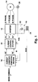
- FIG. 1 shows a system environment suitable for executing each embodiment of the present invention.
- the system shown in FIG. 1 is an electric vehicle drive system and its controller.
- the electric discharge output of a battery 10 is converted from DC to 3-phase AC by an inverter 12 and fed to a PM motor 14.
- the actual battery voltage V dc is considered to determine the field weakening reference current I d * and the reference torque current I q *.
- the maximum motor-applied voltage V MAX changes in correspondence with the fluctuation of the battery voltage V dc .
- the field weakening reference current I d * and the reference torque current I q * computed in accordance with the maximum motor-applied voltage V MAX are also changed.
- This embodiment realizes the optimum field weakening control for preventing too-large or too-small a field weakening current I d from flowing, due to the above control.
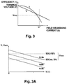
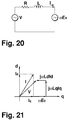
- the field weakening current I d must be controlled so that the terminal voltage V is equal to or less than V MAX .
- I dmin is determined depending on the revolution speed N and the SOC (or V MAX ), as shown in FIG. 3A.
- the reference field current I d * is set in response to the maximum motor-applied voltage V MAX , on the basis of the above described relationship.
- the reference field current I d * is controlled so that it is set larger when the SOC or the maximum motor-applied voltage V MAX decreases, because the absolute value of I dmin becomes large.
- the minimum weakening field current I dmin is obtained, which results in the improved efficiency.
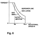
- a vehicle driver can obtain a PM-motor output not limited by I do in the high rotation region by issuing a mode command for selecting the output mode to the current condition computing section 16 independently of degradation of an SOC. That is, when the above field current limitation is executed, the output range of torque T is narrowed to the low-torque side and as a result output limitation occurs since the motor output is determined by TN. Therefore, this embodiment uses the output mode for omitting the steps 116 and 118 so that the output torque T can be secured.
- the output limitation resulting from by the field current limitation does not cause the problem seen in, for example, Japanese Patent Laid-Open No. Hei 5 - 38003.
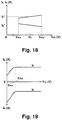
- the output torque T of a PM motor is limited in accordance with degradation of an SOC as shown in FIG. 6.
- the maximum output torque in the high rotation region is changed from an isopower line with a comparatively high power (line where the PM-motor output power obtained as a product of the output torque T and rotational speed N is constant) to an isopower line with less power in accordance with the degradation of an SOC.
- the output torque T is not limited even in the high rotation region as long as the reference torque T* is low.
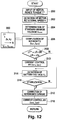
- the current condition computing section 16 first receives the reference torque T* from the supervisor controller (200) and detects the motor rotational speed N with the motor rotational-position sensor 20 (202).
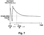
- the current condition computing section 16 waits until the battery voltage V dc is converged (214, 216). Once the battery voltage V dc is sufficiently converged, the current condition computing section 16 corrects the values of the reference current (I d *, I q *) in accordance with a converged battery voltage V S (212) and feeds the corrected reference current (I d *, I q *) to the current control section 18 (212). Thereby, the motor 14 is brought into a state in which the maximum efficiency is obtained.
- the efficiency ⁇ can be prevented from being lowered because a decrease of the battery voltage V dc due to degradation of the SOC does not cause the field weakening current I d to increase. Also in this case, an accelerating performance from standstill is secured because the torque T is secured in a low-rotation high-torque region. Therefore, by using the PM motor as the driving mechanism of an electric vehicle, it is possible to secure a preferable drive feeling.
Landscapes
- Engineering & Computer Science (AREA)
- Power Engineering (AREA)
- Transportation (AREA)
- Mechanical Engineering (AREA)
- Life Sciences & Earth Sciences (AREA)
- Sustainable Development (AREA)
- Sustainable Energy (AREA)
- Control Of Ac Motors In General (AREA)
Applications Claiming Priority (6)
| Application Number | Priority Date | Filing Date | Title |
|---|---|---|---|
| JP198100/93 | 1993-08-10 | ||
| JP19810093 | 1993-08-10 | ||
| JP254152/93 | 1993-10-12 | ||
| JP25415293A JP3146791B2 (ja) | 1993-08-10 | 1993-10-12 | 永久磁石型同期モータの駆動制御装置 |
| JP30544/94 | 1994-02-28 | ||
| JP6030544A JP2959381B2 (ja) | 1994-02-28 | 1994-02-28 | 永久磁石型同期モータの駆動制御装置 |
Publications (3)
| Publication Number | Publication Date |
|---|---|
| EP0638457A2 true EP0638457A2 (de) | 1995-02-15 |
| EP0638457A3 EP0638457A3 (de) | 1995-05-03 |
| EP0638457B1 EP0638457B1 (de) | 1999-03-03 |
Family
ID=27287006
Family Applications (1)
| Application Number | Title | Priority Date | Filing Date |
|---|---|---|---|
| EP94112417A Expired - Lifetime EP0638457B1 (de) | 1993-08-10 | 1994-08-09 | Vorrichtung zum Antrieb und zur Steuerung von Synchronmotoren, die Permanentmagnete als Erregungssystem benützen |
Country Status (3)
| Country | Link |
|---|---|
| US (1) | US5569995A (de) |
| EP (1) | EP0638457B1 (de) |
| DE (1) | DE69416747T2 (de) |
Cited By (25)
| Publication number | Priority date | Publication date | Assignee | Title |
|---|---|---|---|---|
| EP0825059A3 (de) * | 1996-08-22 | 1998-07-29 | Toyota Jidosha Kabushiki Kaisha | Regler für den Antrieb eines permanent magnetischen Synchronmotors |
| EP0793338A4 (de) * | 1995-09-14 | 1998-12-09 | Fanuc Ltd | Verfahren zur stromregelung von servomotoren |
| WO2000049708A1 (en) * | 1999-02-15 | 2000-08-24 | Abb Industry Oy | Method for controlling an electrical machine and an inverter |
| EP0906847A3 (de) * | 1997-10-02 | 2001-08-08 | Siemens Aktiengesellschaft | Antriebsvorrichtung für ein Elektrofahrzeug |
| WO2002025796A1 (de) * | 2000-09-21 | 2002-03-28 | Robert Bosch Gmbh | Elektrische maschine |
| US6550871B1 (en) | 1999-02-19 | 2003-04-22 | Continental Teves, Inc. | Method and system for controlling an electromechanically actuated brake for motor vehicles |
| EP1247687A3 (de) * | 2001-04-04 | 2003-12-03 | Honda Giken Kogyo Kabushiki Kaisha | Regelvorrichtung für einen elektrischen Motor und Regelvorrichtung für ein Hybridfahrzeug |
| EP1193854A4 (de) * | 1999-04-19 | 2004-02-25 | Toyota Motor Co Ltd | Motorregelvorrichtung und regelverfahren |
| WO2004073156A1 (en) * | 2003-02-06 | 2004-08-26 | Wavecrest Laboratories Llc | Adaptive electric motors and generators providing improved performance and efficiency |
| EP1662650A1 (de) * | 2004-11-25 | 2006-05-31 | Kawasaki Jukogyo Kabushiki Kaisha | Verfahren und Vorrichtung zur Steuerung eines Synchronmotors |
| FR2919772A1 (fr) * | 2007-08-03 | 2009-02-06 | Renault Sas | Procede de commande de l'alimentation d'un moteur electrique triphase a partir d'une source de tension continue et dispositif pour sa mise en oeuvre. |
| EP2133991A1 (de) * | 2008-06-09 | 2009-12-16 | Grundfos Management A/S | Kreiselpumpenaggregat |
| WO2010001416A1 (en) * | 2008-07-02 | 2010-01-07 | Tvs Motor Company Limited | Traction control system with variable current limit |
| WO2010001415A1 (en) * | 2008-07-02 | 2010-01-07 | Tvs Motor Company Limited | A controller for an electric traction system |
| EP1748550A4 (de) * | 2004-05-14 | 2010-03-24 | Mitsubishi Electric Corp | Synchron-maschinensteuerung |
| EP1612929A3 (de) * | 2004-06-30 | 2011-03-16 | Fanuc Corporation | Motorreglungsvorrichtung |
| EP1860766A4 (de) * | 2005-03-17 | 2011-06-15 | Nsk Ltd | Elektrische servolenkeinrichtungssteuermethode und vorrichutng |
| WO2012042321A3 (en) * | 2010-09-28 | 2012-11-01 | Nissan Motor Co., Ltd. | Motor controlling apparatus |
| WO2015067593A1 (de) * | 2013-11-06 | 2015-05-14 | Continental Teves Ag & Co. Ohg | Verfahren und vorrichtung zum betreiben einer permanentangeregten synchronmaschine |
| WO2015176756A1 (de) * | 2014-05-21 | 2015-11-26 | Continental Teves Ag & Co. Ohg | Verfahren zur ansteuerung eines bremssystems |
| WO2016016534A1 (fr) * | 2014-07-31 | 2016-02-04 | Renault S.A.S. | Procédé et dispositif de commande du couple électromagnétique d'un groupe motopropulseur |
| EP3010141A1 (de) * | 2014-10-16 | 2016-04-20 | Thales | Vorrichtung zur automatischen und adaptiven feldschwächung, und verfahren zur verwendung einer solchen vorrichtung |
| CN106357185A (zh) * | 2016-11-15 | 2017-01-25 | 吉林大学 | 永磁同步电机转矩控制方法 |
| CN114759838A (zh) * | 2022-06-13 | 2022-07-15 | 常州市常华电机有限公司 | 一种转速控制方法及汽车空调压缩机用同步电机 |
| US12609541B2 (en) | 2021-09-21 | 2026-04-21 | Volvo Car Corporation | Intelligent battery cell |
Families Citing this family (39)
| Publication number | Priority date | Publication date | Assignee | Title |
|---|---|---|---|---|
| JP3345288B2 (ja) * | 1996-12-11 | 2002-11-18 | 株式会社日立製作所 | 電気自動車の制御装置 |
| JP3168967B2 (ja) * | 1997-09-12 | 2001-05-21 | トヨタ自動車株式会社 | 電気角検出装置および方法、並びにモータ制御装置 |
| DE19743757A1 (de) * | 1997-10-02 | 1999-04-15 | Siemens Ag | Antriebsvorrichtung für ein Elektrofahrzeug |
| JPH11122984A (ja) * | 1997-10-09 | 1999-04-30 | Toyota Motor Corp | モータ制御装置および方法 |
| EP1031182B1 (de) * | 1997-11-21 | 2004-02-18 | Continental Teves AG & Co. oHG | Verfahren und schaltungsanordnung zur erzeugung eines pulsbreitenmodulierten stellsignals für einen gleichstromaktuator |
| FI112735B (fi) | 1997-12-03 | 2003-12-31 | Kone Corp | Menetelmä synkronisen kestomagneettimoottorin ohjaamiseksi |
| US6605912B1 (en) | 1998-06-25 | 2003-08-12 | Delphi Technologies, Inc. | Method for controlling a permanent magnet motor |
| US6554088B2 (en) * | 1998-09-14 | 2003-04-29 | Paice Corporation | Hybrid vehicles |
| JP3396440B2 (ja) * | 1999-02-08 | 2003-04-14 | 株式会社日立製作所 | 同期電動機の制御装置 |
| DE19925607A1 (de) * | 1999-02-19 | 2000-08-24 | Continental Teves Ag & Co Ohg | Verfahren und System zur Ansteuerung einer elektromechanisch betätigbaren Bremse für Kraftfahrzeuge |
| JP2001028893A (ja) * | 1999-07-12 | 2001-01-30 | Fanuc Ltd | モータ制御装置 |
| US6163128A (en) * | 1999-08-20 | 2000-12-19 | General Motors Corporation | Method and drive system for controlling a permanent magnet synchronous machine |
| US6288515B1 (en) * | 2000-04-19 | 2001-09-11 | General Motors Corporation | System and method for controlling a surface-mounted permanent magnet synchronous machine drive over a wide speed range using a reference voltage |
| US6407531B1 (en) | 2001-01-09 | 2002-06-18 | Delphi Technologies, Inc. | Method and system for controlling a synchronous machine over full operating range |
| DE10206191B4 (de) * | 2001-11-27 | 2006-02-02 | Siemens Ag | Verfahren zur feldorientierten Regelung einer permanenterregten Synchronmaschine mit Reluktanzmoment |
| US7061736B2 (en) * | 2002-04-01 | 2006-06-13 | International Rectifier Corporation | Method to project electronics from load dump |
| US20040100221A1 (en) * | 2002-11-25 | 2004-05-27 | Zhenxing Fu | Field weakening with full range torque control for synchronous machines |
| JP2005219133A (ja) * | 2004-02-03 | 2005-08-18 | Fanuc Ltd | ロボット用サーボモータ制御装置およびロボット |
| JPWO2005093942A1 (ja) * | 2004-03-24 | 2007-08-30 | 三菱電機株式会社 | 永久磁石式同期モータの制御装置 |
| US7088077B2 (en) * | 2004-11-09 | 2006-08-08 | General Motors Corporation | Position-sensorless control of interior permanent magnet machines |
| US6965212B1 (en) | 2004-11-30 | 2005-11-15 | Honeywell International Inc. | Method and apparatus for field weakening control in an AC motor drive system |
| US20070005203A1 (en) * | 2005-06-30 | 2007-01-04 | Padma Sundaram | Vehicle diagnostic system and method for monitoring vehicle controllers |
| JP5002335B2 (ja) * | 2007-05-29 | 2012-08-15 | 株式会社東芝 | モータ制御装置,洗濯機及びモータ制御方法 |
| JP4696146B2 (ja) * | 2008-06-27 | 2011-06-08 | 株式会社日立製作所 | 断線検出方法および電力変換装置 |
| DE102008042931A1 (de) * | 2008-10-17 | 2010-04-22 | Robert Bosch Gmbh | Verfahren und Vorrichtung zur feldorientierten Regelung einer Synchronmaschine |
| JP5122505B2 (ja) * | 2009-03-09 | 2013-01-16 | 株式会社日立産機システム | 電力変換装置及びその制御方法 |
| JP5494979B2 (ja) * | 2011-01-26 | 2014-05-21 | 三菱自動車工業株式会社 | 電動車両 |
| DE102012202772A1 (de) * | 2012-02-23 | 2013-08-29 | Robert Bosch Gmbh | Kalibrierung und Überwachung eines Winkelmesssystems für elektrische Maschinen |
| US9425729B2 (en) * | 2013-03-15 | 2016-08-23 | Honda Motor Co., Ltd. | Motor control devices and methods |
| US20150061566A1 (en) * | 2013-09-03 | 2015-03-05 | System General Corp. | Control circuit for driving motor and method for controlling speed of motor |
| JP2015082943A (ja) * | 2013-10-24 | 2015-04-27 | トヨタ自動車株式会社 | 車両制御装置 |
| US20150171777A1 (en) * | 2013-12-18 | 2015-06-18 | Hyundai Motor Company | Method for controlling driving motor |
| US9514421B2 (en) * | 2014-03-10 | 2016-12-06 | Regal Beloit America, Inc. | System and method for decommissioning a motor |
| JP6654373B2 (ja) * | 2015-08-04 | 2020-02-26 | 青島海爾洗衣机有限公司QingDao Haier Washing Machine Co.,Ltd. | 洗濯機 |
| WO2017189771A1 (en) | 2016-04-27 | 2017-11-02 | Skogsrud Simen | Method of iterative motion control |
| US11870377B2 (en) * | 2018-12-24 | 2024-01-09 | Quantentech Limited | Multi-phase motor/generator system with harmonic injection |
| EP4219215A3 (de) * | 2019-05-07 | 2023-08-09 | Volvo Car Corporation | System und verfahren zur fehlerhandhabung in einem antriebssystem für ein elektrofahrzeug |
| JP7367373B2 (ja) * | 2019-07-31 | 2023-10-24 | マツダ株式会社 | モータ制御システム |
| CN112428823B (zh) * | 2020-11-26 | 2022-03-15 | 东风商用车有限公司 | 一种电动车永磁同步电机反电动势抑制方法及系统 |
Family Cites Families (21)
| Publication number | Priority date | Publication date | Assignee | Title |
|---|---|---|---|---|
| US3863120A (en) * | 1970-10-20 | 1975-01-28 | Litton Industrial Products | Means for controlling the output condition of a synchronous reluctance motor |
| JPS5930689A (ja) * | 1982-08-05 | 1984-02-18 | 帝人製機株式会社 | ロボツトのテイ−チング補助装置 |
| JPS6016102A (ja) * | 1983-07-08 | 1985-01-26 | Nissan Motor Co Ltd | 電気自動車の走行制御装置 |
| JPS6024676A (ja) * | 1983-07-20 | 1985-02-07 | Toshiba Corp | イメ−ジセンサ駆動方式 |
| JPS60139186A (ja) * | 1983-12-27 | 1985-07-23 | Toshiba Corp | 電動機制御装置 |
| JPS60197183A (ja) * | 1984-03-19 | 1985-10-05 | Mitsubishi Electric Corp | 誘導電動機の速度制御装置 |
| JPS60200791A (ja) * | 1984-03-26 | 1985-10-11 | Mitsubishi Electric Corp | 誘導電動機の速度制御装置 |
| US4616166A (en) * | 1984-12-10 | 1986-10-07 | General Electric Company | Electric power system for starting a large rotatable synchronous machine |
| JPS61262006A (ja) * | 1985-05-14 | 1986-11-20 | Nissan Motor Co Ltd | 車両用誘導電動機の制御装置 |
| JPS6288463A (ja) * | 1985-10-15 | 1987-04-22 | Fujitsu Ltd | 再呼方式 |
| US4677360A (en) * | 1986-03-13 | 1987-06-30 | General Electric Company | Field weakening induction drive |
| JPS6377302A (ja) * | 1986-09-17 | 1988-04-07 | Toyota Motor Corp | 電気自動車の制御装置 |
| US4885518A (en) * | 1987-08-21 | 1989-12-05 | Westinghouse Electric Corp. | Induction motor torque/flux control system |
| JPH01157203A (ja) * | 1987-12-14 | 1989-06-20 | Nissan Motor Co Ltd | 電動車両の速度制御装置 |
| JP2708479B2 (ja) * | 1988-07-22 | 1998-02-04 | 株式会社日立製作所 | 交流サーボモータの制御装置 |
| SE9002420L (sv) * | 1990-07-12 | 1992-01-13 | Skf Ab | Omriktare 3 |
| EP0483894A1 (de) * | 1990-10-29 | 1992-05-06 | General Motors Corporation | Motor-Regelungsystem |
| JPH04285409A (ja) * | 1991-03-12 | 1992-10-09 | Toyota Motor Corp | 電気自動車用駆動制御装置 |
| JP3131248B2 (ja) * | 1991-08-02 | 2001-01-31 | 本田技研工業株式会社 | 電気自動車の走行性能制御装置 |
| JP3200885B2 (ja) * | 1991-10-21 | 2001-08-20 | 株式会社日立製作所 | バッテリー電圧対応型電気自動車制御装置 |
| JP3151887B2 (ja) * | 1991-12-11 | 2001-04-03 | 富士電機株式会社 | 磁束制御形インバータの制御回路 |
-
1994
- 1994-08-09 DE DE69416747T patent/DE69416747T2/de not_active Expired - Lifetime
- 1994-08-09 EP EP94112417A patent/EP0638457B1/de not_active Expired - Lifetime
- 1994-08-10 US US08/288,031 patent/US5569995A/en not_active Expired - Lifetime
Cited By (43)
| Publication number | Priority date | Publication date | Assignee | Title |
|---|---|---|---|---|
| EP0793338A4 (de) * | 1995-09-14 | 1998-12-09 | Fanuc Ltd | Verfahren zur stromregelung von servomotoren |
| EP1504950A1 (de) * | 1996-08-22 | 2005-02-09 | Toyota Jidosha Kabushiki Kaisha | Regler für den Antrieb eines permanent magnetischen Synchronmotors |
| US5883484A (en) * | 1996-08-22 | 1999-03-16 | Toyota Jidosha Kabushiki Kaisha | Controller for driving a permanent magnet type synchronous motor |
| EP0825059A3 (de) * | 1996-08-22 | 1998-07-29 | Toyota Jidosha Kabushiki Kaisha | Regler für den Antrieb eines permanent magnetischen Synchronmotors |
| EP1500549A3 (de) * | 1996-08-22 | 2005-02-09 | Toyota Jidosha Kabushiki Kaisha | Regler für den Antrieb eines permanent magnetischen Synchronmotors |
| EP0906847A3 (de) * | 1997-10-02 | 2001-08-08 | Siemens Aktiengesellschaft | Antriebsvorrichtung für ein Elektrofahrzeug |
| WO2000049708A1 (en) * | 1999-02-15 | 2000-08-24 | Abb Industry Oy | Method for controlling an electrical machine and an inverter |
| US6597148B1 (en) | 1999-02-15 | 2003-07-22 | Abb Oy | Method for controlling an electrical machine and an inverter |
| US6550871B1 (en) | 1999-02-19 | 2003-04-22 | Continental Teves, Inc. | Method and system for controlling an electromechanically actuated brake for motor vehicles |
| EP1193854A4 (de) * | 1999-04-19 | 2004-02-25 | Toyota Motor Co Ltd | Motorregelvorrichtung und regelverfahren |
| WO2002025796A1 (de) * | 2000-09-21 | 2002-03-28 | Robert Bosch Gmbh | Elektrische maschine |
| US6703756B2 (en) | 2000-09-21 | 2004-03-09 | Robert Bosch Gmbh | Electrical machine |
| EP1247687A3 (de) * | 2001-04-04 | 2003-12-03 | Honda Giken Kogyo Kabushiki Kaisha | Regelvorrichtung für einen elektrischen Motor und Regelvorrichtung für ein Hybridfahrzeug |
| WO2004073156A1 (en) * | 2003-02-06 | 2004-08-26 | Wavecrest Laboratories Llc | Adaptive electric motors and generators providing improved performance and efficiency |
| EP1748550A4 (de) * | 2004-05-14 | 2010-03-24 | Mitsubishi Electric Corp | Synchron-maschinensteuerung |
| EP1612929A3 (de) * | 2004-06-30 | 2011-03-16 | Fanuc Corporation | Motorreglungsvorrichtung |
| US7235947B2 (en) | 2004-11-25 | 2007-06-26 | Kawasaki Jukogyo Kabushiki Kaisha | Synchronous motor control method and synchronous motor control system |
| EP1662650A1 (de) * | 2004-11-25 | 2006-05-31 | Kawasaki Jukogyo Kabushiki Kaisha | Verfahren und Vorrichtung zur Steuerung eines Synchronmotors |
| US8285451B2 (en) | 2005-03-17 | 2012-10-09 | Nsk Ltd. | Method and apparatus for controlling electric power steering system |
| EP1860766A4 (de) * | 2005-03-17 | 2011-06-15 | Nsk Ltd | Elektrische servolenkeinrichtungssteuermethode und vorrichutng |
| WO2009019390A3 (fr) * | 2007-08-03 | 2009-04-30 | Renault Sa | Procede de commande de l'alimentation d'un moteur electrique triphase a partir d'une source de tension continue et dispositif pour sa mise en oeuvre |
| FR2919772A1 (fr) * | 2007-08-03 | 2009-02-06 | Renault Sas | Procede de commande de l'alimentation d'un moteur electrique triphase a partir d'une source de tension continue et dispositif pour sa mise en oeuvre. |
| US8690549B2 (en) | 2008-06-09 | 2014-04-08 | Grundfos Management A/S | Centrifugal pump unit |
| WO2009149796A3 (de) * | 2008-06-09 | 2010-03-18 | Grundfos Management A/S | Kreiselpumpenaggregat |
| CN102057566B (zh) * | 2008-06-09 | 2014-06-11 | 格伦德福斯管理联合股份公司 | 离心泵组 |
| EP2133991A1 (de) * | 2008-06-09 | 2009-12-16 | Grundfos Management A/S | Kreiselpumpenaggregat |
| WO2010001415A1 (en) * | 2008-07-02 | 2010-01-07 | Tvs Motor Company Limited | A controller for an electric traction system |
| WO2010001416A1 (en) * | 2008-07-02 | 2010-01-07 | Tvs Motor Company Limited | Traction control system with variable current limit |
| WO2012042321A3 (en) * | 2010-09-28 | 2012-11-01 | Nissan Motor Co., Ltd. | Motor controlling apparatus |
| KR101460461B1 (ko) | 2010-09-28 | 2014-11-11 | 닛산 지도우샤 가부시키가이샤 | 모터 제어 장치 |
| US9030136B2 (en) | 2010-09-28 | 2015-05-12 | Nissan Motor Co., Ltd. | Motor controlling apparatus |
| WO2015067593A1 (de) * | 2013-11-06 | 2015-05-14 | Continental Teves Ag & Co. Ohg | Verfahren und vorrichtung zum betreiben einer permanentangeregten synchronmaschine |
| CN106416050B (zh) * | 2014-05-21 | 2019-10-22 | 大陆-特韦斯贸易合伙股份公司及两合公司 | 用于控制制动系统的方法 |
| CN106416050A (zh) * | 2014-05-21 | 2017-02-15 | 大陆-特韦斯贸易合伙股份公司及两合公司 | 用于控制制动系统的方法 |
| WO2015176756A1 (de) * | 2014-05-21 | 2015-11-26 | Continental Teves Ag & Co. Ohg | Verfahren zur ansteuerung eines bremssystems |
| US10604127B2 (en) | 2014-05-21 | 2020-03-31 | Continental Teves Ag & Co. Ohg | Method for controlling a brake system |
| WO2016016534A1 (fr) * | 2014-07-31 | 2016-02-04 | Renault S.A.S. | Procédé et dispositif de commande du couple électromagnétique d'un groupe motopropulseur |
| FR3024616A1 (fr) * | 2014-07-31 | 2016-02-05 | Renault Sas | Procede et dispositif de commande du couple electromagnetique d'un groupe motopropulseur |
| EP3010141A1 (de) * | 2014-10-16 | 2016-04-20 | Thales | Vorrichtung zur automatischen und adaptiven feldschwächung, und verfahren zur verwendung einer solchen vorrichtung |
| US9692338B2 (en) | 2014-10-16 | 2017-06-27 | Thales | Automatic and adaptive defluxing device and method implementing such a device |
| CN106357185A (zh) * | 2016-11-15 | 2017-01-25 | 吉林大学 | 永磁同步电机转矩控制方法 |
| US12609541B2 (en) | 2021-09-21 | 2026-04-21 | Volvo Car Corporation | Intelligent battery cell |
| CN114759838A (zh) * | 2022-06-13 | 2022-07-15 | 常州市常华电机有限公司 | 一种转速控制方法及汽车空调压缩机用同步电机 |
Also Published As
| Publication number | Publication date |
|---|---|
| US5569995A (en) | 1996-10-29 |
| DE69416747T2 (de) | 1999-07-29 |
| EP0638457B1 (de) | 1999-03-03 |
| DE69416747D1 (de) | 1999-04-08 |
| EP0638457A3 (de) | 1995-05-03 |
Similar Documents
| Publication | Publication Date | Title |
|---|---|---|
| US5569995A (en) | Method and apparatus for driving and controlling synchronous motor using permanent magnets as its field system | |
| JP3396440B2 (ja) | 同期電動機の制御装置 | |
| US7728541B2 (en) | Electric motor drive control method and apparatus | |
| US5990657A (en) | Inverter system and control system for electric vehicle | |
| US8281886B2 (en) | Electric motor control device, drive device and hybrid drive device | |
| US8278854B2 (en) | Control device for electric rotating machine | |
| US6771039B2 (en) | Motor control apparatus and method | |
| US7595600B2 (en) | Method and system for torque control in permanent magnet machines | |
| EP1748550B1 (de) | Synchron-maschinensteuerung | |
| US8228016B2 (en) | Gain adjustment to improve torque linearity in a field weakening region | |
| US10778130B2 (en) | Control apparatus for alternating-current rotary electric machine | |
| JP3146791B2 (ja) | 永久磁石型同期モータの駆動制御装置 | |
| US6194865B1 (en) | Control method and system for electric rotary machine | |
| US7012389B2 (en) | Electric drive control apparatus, electric drive control method and program thereof | |
| US20190229664A1 (en) | Control apparatus for alternating-current rotary electric machine | |
| US8148926B2 (en) | Permanent magnet synchronization motor vector control device | |
| JPH1118496A (ja) | 電気車の制御装置および制御方法 | |
| US7235937B2 (en) | Traction motor control system | |
| JPH11299297A (ja) | 永久磁石同期電動機の制御装置 | |
| JP3289618B2 (ja) | モータ制御装置 | |
| JPH1169900A (ja) | 電気車の制御装置 | |
| US12237784B2 (en) | Motor control device | |
| JP3542741B2 (ja) | 電気車の制御装置及び制御方法 | |
| JP2959381B2 (ja) | 永久磁石型同期モータの駆動制御装置 | |
| JPH10117403A (ja) | 電気車用ハイブリッド駆動システム |
Legal Events
| Date | Code | Title | Description |
|---|---|---|---|
| PUAI | Public reference made under article 153(3) epc to a published international application that has entered the european phase |
Free format text: ORIGINAL CODE: 0009012 |
|
| 17P | Request for examination filed |
Effective date: 19940809 |
|
| AK | Designated contracting states |
Kind code of ref document: A2 Designated state(s): DE FR GB |
|
| PUAL | Search report despatched |
Free format text: ORIGINAL CODE: 0009013 |
|
| AK | Designated contracting states |
Kind code of ref document: A3 Designated state(s): DE FR GB |
|
| 17Q | First examination report despatched |
Effective date: 19960628 |
|
| GRAG | Despatch of communication of intention to grant |
Free format text: ORIGINAL CODE: EPIDOS AGRA |
|
| GRAG | Despatch of communication of intention to grant |
Free format text: ORIGINAL CODE: EPIDOS AGRA |
|
| GRAG | Despatch of communication of intention to grant |
Free format text: ORIGINAL CODE: EPIDOS AGRA |
|
| GRAH | Despatch of communication of intention to grant a patent |
Free format text: ORIGINAL CODE: EPIDOS IGRA |
|
| GRAH | Despatch of communication of intention to grant a patent |
Free format text: ORIGINAL CODE: EPIDOS IGRA |
|
| GRAA | (expected) grant |
Free format text: ORIGINAL CODE: 0009210 |
|
| AK | Designated contracting states |
Kind code of ref document: B1 Designated state(s): DE FR GB |
|
| REF | Corresponds to: |
Ref document number: 69416747 Country of ref document: DE Date of ref document: 19990408 |
|
| ET | Fr: translation filed | ||
| PLBE | No opposition filed within time limit |
Free format text: ORIGINAL CODE: 0009261 |
|
| STAA | Information on the status of an ep patent application or granted ep patent |
Free format text: STATUS: NO OPPOSITION FILED WITHIN TIME LIMIT |
|
| 26N | No opposition filed | ||
| REG | Reference to a national code |
Ref country code: GB Ref legal event code: IF02 |
|
| REG | Reference to a national code |
Ref country code: GB Ref legal event code: 746 Effective date: 20111114 |
|
| REG | Reference to a national code |
Ref country code: DE Ref legal event code: R084 Ref document number: 69416747 Country of ref document: DE Effective date: 20111109 |
|
| PGFP | Annual fee paid to national office [announced via postgrant information from national office to epo] |
Ref country code: DE Payment date: 20130807 Year of fee payment: 20 |
|
| PGFP | Annual fee paid to national office [announced via postgrant information from national office to epo] |
Ref country code: FR Payment date: 20130808 Year of fee payment: 20 Ref country code: GB Payment date: 20130807 Year of fee payment: 20 |
|
| REG | Reference to a national code |
Ref country code: DE Ref legal event code: R071 Ref document number: 69416747 Country of ref document: DE |
|
| REG | Reference to a national code |
Ref country code: DE Ref legal event code: R071 Ref document number: 69416747 Country of ref document: DE |
|
| REG | Reference to a national code |
Ref country code: GB Ref legal event code: PE20 Expiry date: 20140808 |
|
| PG25 | Lapsed in a contracting state [announced via postgrant information from national office to epo] |
Ref country code: DE Free format text: LAPSE BECAUSE OF EXPIRATION OF PROTECTION Effective date: 20140812 |
|
| PG25 | Lapsed in a contracting state [announced via postgrant information from national office to epo] |
Ref country code: GB Free format text: LAPSE BECAUSE OF EXPIRATION OF PROTECTION Effective date: 20140808 |