EP0637157A2 - Verfahren und Gerät zur Systemsteuerung - Google Patents
Verfahren und Gerät zur Systemsteuerung Download PDFInfo
- Publication number
- EP0637157A2 EP0637157A2 EP94305654A EP94305654A EP0637157A2 EP 0637157 A2 EP0637157 A2 EP 0637157A2 EP 94305654 A EP94305654 A EP 94305654A EP 94305654 A EP94305654 A EP 94305654A EP 0637157 A2 EP0637157 A2 EP 0637157A2
- Authority
- EP
- European Patent Office
- Prior art keywords
- multimedia
- controller
- devices
- data
- connection
- Prior art date
- Legal status (The legal status is an assumption and is not a legal conclusion. Google has not performed a legal analysis and makes no representation as to the accuracy of the status listed.)
- Granted
Links
- 238000000034 method Methods 0.000 title claims description 142
- 230000002093 peripheral effect Effects 0.000 claims abstract description 98
- 230000006854 communication Effects 0.000 claims abstract description 67
- 238000004891 communication Methods 0.000 claims abstract description 67
- 238000012545 processing Methods 0.000 claims description 100
- 230000006870 function Effects 0.000 claims description 66
- 238000012790 confirmation Methods 0.000 claims description 40
- 230000004044 response Effects 0.000 claims description 16
- 239000000470 constituent Substances 0.000 claims description 6
- 230000007246 mechanism Effects 0.000 claims description 4
- 230000003213 activating effect Effects 0.000 claims 2
- 230000002708 enhancing effect Effects 0.000 claims 1
- 238000010276 construction Methods 0.000 description 34
- 230000008569 process Effects 0.000 description 34
- 238000010586 diagram Methods 0.000 description 23
- 230000002159 abnormal effect Effects 0.000 description 4
- 230000005856 abnormality Effects 0.000 description 4
- 230000006835 compression Effects 0.000 description 4
- 238000007906 compression Methods 0.000 description 4
- 230000008901 benefit Effects 0.000 description 3
- 230000007175 bidirectional communication Effects 0.000 description 3
- 230000015572 biosynthetic process Effects 0.000 description 3
- 238000001514 detection method Methods 0.000 description 3
- 230000000694 effects Effects 0.000 description 3
- 230000003287 optical effect Effects 0.000 description 3
- 235000019640 taste Nutrition 0.000 description 3
- 230000005540 biological transmission Effects 0.000 description 2
- 230000008859 change Effects 0.000 description 2
- 238000006243 chemical reaction Methods 0.000 description 2
- 239000003086 colorant Substances 0.000 description 2
- 230000010365 information processing Effects 0.000 description 2
- 230000007257 malfunction Effects 0.000 description 2
- 238000012986 modification Methods 0.000 description 2
- 230000004048 modification Effects 0.000 description 2
- 238000003825 pressing Methods 0.000 description 2
- 238000012546 transfer Methods 0.000 description 2
- 230000000007 visual effect Effects 0.000 description 2
- 241000244206 Nematoda Species 0.000 description 1
- 230000004913 activation Effects 0.000 description 1
- 239000002131 composite material Substances 0.000 description 1
- 238000013461 design Methods 0.000 description 1
- 238000011161 development Methods 0.000 description 1
- 238000005538 encapsulation Methods 0.000 description 1
- 239000000835 fiber Substances 0.000 description 1
- 230000014509 gene expression Effects 0.000 description 1
- 230000001771 impaired effect Effects 0.000 description 1
- 238000003780 insertion Methods 0.000 description 1
- 230000037431 insertion Effects 0.000 description 1
- 230000002452 interceptive effect Effects 0.000 description 1
- 238000012544 monitoring process Methods 0.000 description 1
- 238000010422 painting Methods 0.000 description 1
- 230000000737 periodic effect Effects 0.000 description 1
- 239000004065 semiconductor Substances 0.000 description 1
- 239000007787 solid Substances 0.000 description 1
- 230000005236 sound signal Effects 0.000 description 1
- 230000001360 synchronised effect Effects 0.000 description 1
Images


Classifications
-
- H—ELECTRICITY
- H04—ELECTRIC COMMUNICATION TECHNIQUE
- H04L—TRANSMISSION OF DIGITAL INFORMATION, e.g. TELEGRAPHIC COMMUNICATION
- H04L41/00—Arrangements for maintenance, administration or management of data switching networks, e.g. of packet switching networks
- H04L41/22—Arrangements for maintenance, administration or management of data switching networks, e.g. of packet switching networks comprising specially adapted graphical user interfaces [GUI]
-
- G—PHYSICS
- G06—COMPUTING; CALCULATING OR COUNTING
- G06F—ELECTRIC DIGITAL DATA PROCESSING
- G06F15/00—Digital computers in general; Data processing equipment in general
- G06F15/16—Combinations of two or more digital computers each having at least an arithmetic unit, a program unit and a register, e.g. for a simultaneous processing of several programs
-
- G—PHYSICS
- G06—COMPUTING; CALCULATING OR COUNTING
- G06F—ELECTRIC DIGITAL DATA PROCESSING
- G06F13/00—Interconnection of, or transfer of information or other signals between, memories, input/output devices or central processing units
- G06F13/10—Program control for peripheral devices
-
- G—PHYSICS
- G06—COMPUTING; CALCULATING OR COUNTING
- G06F—ELECTRIC DIGITAL DATA PROCESSING
- G06F3/00—Input arrangements for transferring data to be processed into a form capable of being handled by the computer; Output arrangements for transferring data from processing unit to output unit, e.g. interface arrangements
- G06F3/01—Input arrangements or combined input and output arrangements for interaction between user and computer
- G06F3/048—Interaction techniques based on graphical user interfaces [GUI]
- G06F3/0481—Interaction techniques based on graphical user interfaces [GUI] based on specific properties of the displayed interaction object or a metaphor-based environment, e.g. interaction with desktop elements like windows or icons, or assisted by a cursor's changing behaviour or appearance
-
- G—PHYSICS
- G11—INFORMATION STORAGE
- G11B—INFORMATION STORAGE BASED ON RELATIVE MOVEMENT BETWEEN RECORD CARRIER AND TRANSDUCER
- G11B27/00—Editing; Indexing; Addressing; Timing or synchronising; Monitoring; Measuring tape travel
- G11B27/002—Programmed access in sequence to a plurality of record carriers or indexed parts, e.g. tracks, thereof, e.g. for editing
-
- G—PHYSICS
- G11—INFORMATION STORAGE
- G11B—INFORMATION STORAGE BASED ON RELATIVE MOVEMENT BETWEEN RECORD CARRIER AND TRANSDUCER
- G11B27/00—Editing; Indexing; Addressing; Timing or synchronising; Monitoring; Measuring tape travel
- G11B27/10—Indexing; Addressing; Timing or synchronising; Measuring tape travel
- G11B27/34—Indicating arrangements
-
- H—ELECTRICITY
- H04—ELECTRIC COMMUNICATION TECHNIQUE
- H04L—TRANSMISSION OF DIGITAL INFORMATION, e.g. TELEGRAPHIC COMMUNICATION
- H04L12/00—Data switching networks
- H04L12/28—Data switching networks characterised by path configuration, e.g. LAN [Local Area Networks] or WAN [Wide Area Networks]
- H04L12/2803—Home automation networks
- H04L12/2807—Exchanging configuration information on appliance services in a home automation network
- H04L12/281—Exchanging configuration information on appliance services in a home automation network indicating a format for calling an appliance service function in a home automation network
-
- H—ELECTRICITY
- H04—ELECTRIC COMMUNICATION TECHNIQUE
- H04L—TRANSMISSION OF DIGITAL INFORMATION, e.g. TELEGRAPHIC COMMUNICATION
- H04L12/00—Data switching networks
- H04L12/28—Data switching networks characterised by path configuration, e.g. LAN [Local Area Networks] or WAN [Wide Area Networks]
- H04L12/2803—Home automation networks
- H04L12/2816—Controlling appliance services of a home automation network by calling their functionalities
- H04L12/282—Controlling appliance services of a home automation network by calling their functionalities based on user interaction within the home
-
- H—ELECTRICITY
- H04—ELECTRIC COMMUNICATION TECHNIQUE
- H04L—TRANSMISSION OF DIGITAL INFORMATION, e.g. TELEGRAPHIC COMMUNICATION
- H04L41/00—Arrangements for maintenance, administration or management of data switching networks, e.g. of packet switching networks
- H04L41/12—Discovery or management of network topologies
-
- H—ELECTRICITY
- H04—ELECTRIC COMMUNICATION TECHNIQUE
- H04L—TRANSMISSION OF DIGITAL INFORMATION, e.g. TELEGRAPHIC COMMUNICATION
- H04L41/00—Arrangements for maintenance, administration or management of data switching networks, e.g. of packet switching networks
- H04L41/34—Signalling channels for network management communication
-
- H—ELECTRICITY
- H04—ELECTRIC COMMUNICATION TECHNIQUE
- H04L—TRANSMISSION OF DIGITAL INFORMATION, e.g. TELEGRAPHIC COMMUNICATION
- H04L61/00—Network arrangements, protocols or services for addressing or naming
- H04L61/45—Network directories; Name-to-address mapping
- H04L61/4541—Directories for service discovery
-
- H—ELECTRICITY
- H04—ELECTRIC COMMUNICATION TECHNIQUE
- H04L—TRANSMISSION OF DIGITAL INFORMATION, e.g. TELEGRAPHIC COMMUNICATION
- H04L65/00—Network arrangements, protocols or services for supporting real-time applications in data packet communication
- H04L65/1066—Session management
- H04L65/1101—Session protocols
-
- H—ELECTRICITY
- H04—ELECTRIC COMMUNICATION TECHNIQUE
- H04L—TRANSMISSION OF DIGITAL INFORMATION, e.g. TELEGRAPHIC COMMUNICATION
- H04L67/00—Network arrangements or protocols for supporting network services or applications
- H04L67/01—Protocols
- H04L67/12—Protocols specially adapted for proprietary or special-purpose networking environments, e.g. medical networks, sensor networks, networks in vehicles or remote metering networks
- H04L67/125—Protocols specially adapted for proprietary or special-purpose networking environments, e.g. medical networks, sensor networks, networks in vehicles or remote metering networks involving control of end-device applications over a network
-
- H—ELECTRICITY
- H04—ELECTRIC COMMUNICATION TECHNIQUE
- H04L—TRANSMISSION OF DIGITAL INFORMATION, e.g. TELEGRAPHIC COMMUNICATION
- H04L67/00—Network arrangements or protocols for supporting network services or applications
- H04L67/50—Network services
- H04L67/75—Indicating network or usage conditions on the user display
-
- H—ELECTRICITY
- H04—ELECTRIC COMMUNICATION TECHNIQUE
- H04L—TRANSMISSION OF DIGITAL INFORMATION, e.g. TELEGRAPHIC COMMUNICATION
- H04L9/00—Cryptographic mechanisms or cryptographic arrangements for secret or secure communications; Network security protocols
- H04L9/40—Network security protocols
-
- H—ELECTRICITY
- H04—ELECTRIC COMMUNICATION TECHNIQUE
- H04N—PICTORIAL COMMUNICATION, e.g. TELEVISION
- H04N21/00—Selective content distribution, e.g. interactive television or video on demand [VOD]
- H04N21/40—Client devices specifically adapted for the reception of or interaction with content, e.g. set-top-box [STB]; Operations thereof
- H04N21/41—Structure of client; Structure of client peripherals
- H04N21/4104—Peripherals receiving signals from specially adapted client devices
- H04N21/4108—Peripherals receiving signals from specially adapted client devices characterised by an identification number or address, e.g. local network address
-
- H—ELECTRICITY
- H04—ELECTRIC COMMUNICATION TECHNIQUE
- H04N—PICTORIAL COMMUNICATION, e.g. TELEVISION
- H04N21/00—Selective content distribution, e.g. interactive television or video on demand [VOD]
- H04N21/40—Client devices specifically adapted for the reception of or interaction with content, e.g. set-top-box [STB]; Operations thereof
- H04N21/41—Structure of client; Structure of client peripherals
- H04N21/4104—Peripherals receiving signals from specially adapted client devices
- H04N21/4135—Peripherals receiving signals from specially adapted client devices external recorder
-
- H—ELECTRICITY
- H04—ELECTRIC COMMUNICATION TECHNIQUE
- H04N—PICTORIAL COMMUNICATION, e.g. TELEVISION
- H04N21/00—Selective content distribution, e.g. interactive television or video on demand [VOD]
- H04N21/40—Client devices specifically adapted for the reception of or interaction with content, e.g. set-top-box [STB]; Operations thereof
- H04N21/41—Structure of client; Structure of client peripherals
- H04N21/422—Input-only peripherals, i.e. input devices connected to specially adapted client devices, e.g. global positioning system [GPS]
- H04N21/42204—User interfaces specially adapted for controlling a client device through a remote control device; Remote control devices therefor
-
- H—ELECTRICITY
- H04—ELECTRIC COMMUNICATION TECHNIQUE
- H04N—PICTORIAL COMMUNICATION, e.g. TELEVISION
- H04N21/00—Selective content distribution, e.g. interactive television or video on demand [VOD]
- H04N21/40—Client devices specifically adapted for the reception of or interaction with content, e.g. set-top-box [STB]; Operations thereof
- H04N21/41—Structure of client; Structure of client peripherals
- H04N21/426—Internal components of the client ; Characteristics thereof
-
- H—ELECTRICITY
- H04—ELECTRIC COMMUNICATION TECHNIQUE
- H04N—PICTORIAL COMMUNICATION, e.g. TELEVISION
- H04N21/00—Selective content distribution, e.g. interactive television or video on demand [VOD]
- H04N21/40—Client devices specifically adapted for the reception of or interaction with content, e.g. set-top-box [STB]; Operations thereof
- H04N21/43—Processing of content or additional data, e.g. demultiplexing additional data from a digital video stream; Elementary client operations, e.g. monitoring of home network or synchronising decoder's clock; Client middleware
- H04N21/431—Generation of visual interfaces for content selection or interaction; Content or additional data rendering
- H04N21/4312—Generation of visual interfaces for content selection or interaction; Content or additional data rendering involving specific graphical features, e.g. screen layout, special fonts or colors, blinking icons, highlights or animations
-
- H—ELECTRICITY
- H04—ELECTRIC COMMUNICATION TECHNIQUE
- H04N—PICTORIAL COMMUNICATION, e.g. TELEVISION
- H04N21/00—Selective content distribution, e.g. interactive television or video on demand [VOD]
- H04N21/40—Client devices specifically adapted for the reception of or interaction with content, e.g. set-top-box [STB]; Operations thereof
- H04N21/43—Processing of content or additional data, e.g. demultiplexing additional data from a digital video stream; Elementary client operations, e.g. monitoring of home network or synchronising decoder's clock; Client middleware
- H04N21/436—Interfacing a local distribution network, e.g. communicating with another STB or one or more peripheral devices inside the home
- H04N21/4363—Adapting the video or multiplex stream to a specific local network, e.g. a IEEE 1394 or Bluetooth® network
- H04N21/43632—Adapting the video or multiplex stream to a specific local network, e.g. a IEEE 1394 or Bluetooth® network involving a wired protocol, e.g. IEEE 1394
-
- H—ELECTRICITY
- H04—ELECTRIC COMMUNICATION TECHNIQUE
- H04N—PICTORIAL COMMUNICATION, e.g. TELEVISION
- H04N21/00—Selective content distribution, e.g. interactive television or video on demand [VOD]
- H04N21/40—Client devices specifically adapted for the reception of or interaction with content, e.g. set-top-box [STB]; Operations thereof
- H04N21/43—Processing of content or additional data, e.g. demultiplexing additional data from a digital video stream; Elementary client operations, e.g. monitoring of home network or synchronising decoder's clock; Client middleware
- H04N21/442—Monitoring of processes or resources, e.g. detecting the failure of a recording device, monitoring the downstream bandwidth, the number of times a movie has been viewed, the storage space available from the internal hard disk
- H04N21/44227—Monitoring of local network, e.g. connection or bandwidth variations; Detecting new devices in the local network
-
- H—ELECTRICITY
- H04—ELECTRIC COMMUNICATION TECHNIQUE
- H04N—PICTORIAL COMMUNICATION, e.g. TELEVISION
- H04N21/00—Selective content distribution, e.g. interactive television or video on demand [VOD]
- H04N21/40—Client devices specifically adapted for the reception of or interaction with content, e.g. set-top-box [STB]; Operations thereof
- H04N21/47—End-user applications
- H04N21/472—End-user interface for requesting content, additional data or services; End-user interface for interacting with content, e.g. for content reservation or setting reminders, for requesting event notification, for manipulating displayed content
- H04N21/47217—End-user interface for requesting content, additional data or services; End-user interface for interacting with content, e.g. for content reservation or setting reminders, for requesting event notification, for manipulating displayed content for controlling playback functions for recorded or on-demand content, e.g. using progress bars, mode or play-point indicators or bookmarks
-
- H—ELECTRICITY
- H04—ELECTRIC COMMUNICATION TECHNIQUE
- H04N—PICTORIAL COMMUNICATION, e.g. TELEVISION
- H04N21/00—Selective content distribution, e.g. interactive television or video on demand [VOD]
- H04N21/40—Client devices specifically adapted for the reception of or interaction with content, e.g. set-top-box [STB]; Operations thereof
- H04N21/47—End-user applications
- H04N21/482—End-user interface for program selection
-
- H—ELECTRICITY
- H04—ELECTRIC COMMUNICATION TECHNIQUE
- H04N—PICTORIAL COMMUNICATION, e.g. TELEVISION
- H04N21/00—Selective content distribution, e.g. interactive television or video on demand [VOD]
- H04N21/40—Client devices specifically adapted for the reception of or interaction with content, e.g. set-top-box [STB]; Operations thereof
- H04N21/47—End-user applications
- H04N21/485—End-user interface for client configuration
-
- H—ELECTRICITY
- H04—ELECTRIC COMMUNICATION TECHNIQUE
- H04N—PICTORIAL COMMUNICATION, e.g. TELEVISION
- H04N21/00—Selective content distribution, e.g. interactive television or video on demand [VOD]
- H04N21/40—Client devices specifically adapted for the reception of or interaction with content, e.g. set-top-box [STB]; Operations thereof
- H04N21/47—End-user applications
- H04N21/488—Data services, e.g. news ticker
- H04N21/4882—Data services, e.g. news ticker for displaying messages, e.g. warnings, reminders
-
- H—ELECTRICITY
- H04—ELECTRIC COMMUNICATION TECHNIQUE
- H04N—PICTORIAL COMMUNICATION, e.g. TELEVISION
- H04N5/00—Details of television systems
- H04N5/76—Television signal recording
- H04N5/765—Interface circuits between an apparatus for recording and another apparatus
-
- H—ELECTRICITY
- H04—ELECTRIC COMMUNICATION TECHNIQUE
- H04N—PICTORIAL COMMUNICATION, e.g. TELEVISION
- H04N5/00—Details of television systems
- H04N5/76—Television signal recording
- H04N5/78—Television signal recording using magnetic recording
- H04N5/782—Television signal recording using magnetic recording on tape
-
- H—ELECTRICITY
- H04—ELECTRIC COMMUNICATION TECHNIQUE
- H04L—TRANSMISSION OF DIGITAL INFORMATION, e.g. TELEGRAPHIC COMMUNICATION
- H04L12/00—Data switching networks
- H04L12/28—Data switching networks characterised by path configuration, e.g. LAN [Local Area Networks] or WAN [Wide Area Networks]
- H04L12/2803—Home automation networks
- H04L12/2807—Exchanging configuration information on appliance services in a home automation network
- H04L12/2809—Exchanging configuration information on appliance services in a home automation network indicating that an appliance service is present in a home automation network
-
- H—ELECTRICITY
- H04—ELECTRIC COMMUNICATION TECHNIQUE
- H04L—TRANSMISSION OF DIGITAL INFORMATION, e.g. TELEGRAPHIC COMMUNICATION
- H04L12/00—Data switching networks
- H04L12/28—Data switching networks characterised by path configuration, e.g. LAN [Local Area Networks] or WAN [Wide Area Networks]
- H04L12/2803—Home automation networks
- H04L2012/2847—Home automation networks characterised by the type of home appliance used
- H04L2012/2849—Audio/video appliances
-
- H—ELECTRICITY
- H04—ELECTRIC COMMUNICATION TECHNIQUE
- H04L—TRANSMISSION OF DIGITAL INFORMATION, e.g. TELEGRAPHIC COMMUNICATION
- H04L41/00—Arrangements for maintenance, administration or management of data switching networks, e.g. of packet switching networks
- H04L41/08—Configuration management of networks or network elements
-
- H—ELECTRICITY
- H04—ELECTRIC COMMUNICATION TECHNIQUE
- H04L—TRANSMISSION OF DIGITAL INFORMATION, e.g. TELEGRAPHIC COMMUNICATION
- H04L65/00—Network arrangements, protocols or services for supporting real-time applications in data packet communication
- H04L65/10—Architectures or entities
- H04L65/1059—End-user terminal functionalities specially adapted for real-time communication
-
- H—ELECTRICITY
- H04—ELECTRIC COMMUNICATION TECHNIQUE
- H04L—TRANSMISSION OF DIGITAL INFORMATION, e.g. TELEGRAPHIC COMMUNICATION
- H04L67/00—Network arrangements or protocols for supporting network services or applications
-
- H—ELECTRICITY
- H04—ELECTRIC COMMUNICATION TECHNIQUE
- H04L—TRANSMISSION OF DIGITAL INFORMATION, e.g. TELEGRAPHIC COMMUNICATION
- H04L69/00—Network arrangements, protocols or services independent of the application payload and not provided for in the other groups of this subclass
- H04L69/30—Definitions, standards or architectural aspects of layered protocol stacks
- H04L69/32—Architecture of open systems interconnection [OSI] 7-layer type protocol stacks, e.g. the interfaces between the data link level and the physical level
- H04L69/322—Intralayer communication protocols among peer entities or protocol data unit [PDU] definitions
- H04L69/329—Intralayer communication protocols among peer entities or protocol data unit [PDU] definitions in the application layer [OSI layer 7]
-
- H—ELECTRICITY
- H04—ELECTRIC COMMUNICATION TECHNIQUE
- H04N—PICTORIAL COMMUNICATION, e.g. TELEVISION
- H04N21/00—Selective content distribution, e.g. interactive television or video on demand [VOD]
- H04N21/40—Client devices specifically adapted for the reception of or interaction with content, e.g. set-top-box [STB]; Operations thereof
- H04N21/43—Processing of content or additional data, e.g. demultiplexing additional data from a digital video stream; Elementary client operations, e.g. monitoring of home network or synchronising decoder's clock; Client middleware
- H04N21/431—Generation of visual interfaces for content selection or interaction; Content or additional data rendering
- H04N21/4312—Generation of visual interfaces for content selection or interaction; Content or additional data rendering involving specific graphical features, e.g. screen layout, special fonts or colors, blinking icons, highlights or animations
- H04N21/4316—Generation of visual interfaces for content selection or interaction; Content or additional data rendering involving specific graphical features, e.g. screen layout, special fonts or colors, blinking icons, highlights or animations for displaying supplemental content in a region of the screen, e.g. an advertisement in a separate window
-
- H—ELECTRICITY
- H04—ELECTRIC COMMUNICATION TECHNIQUE
- H04N—PICTORIAL COMMUNICATION, e.g. TELEVISION
- H04N5/00—Details of television systems
- H04N5/76—Television signal recording
- H04N5/765—Interface circuits between an apparatus for recording and another apparatus
- H04N5/77—Interface circuits between an apparatus for recording and another apparatus between a recording apparatus and a television camera
- H04N5/772—Interface circuits between an apparatus for recording and another apparatus between a recording apparatus and a television camera the recording apparatus and the television camera being placed in the same enclosure
-
- H—ELECTRICITY
- H04—ELECTRIC COMMUNICATION TECHNIQUE
- H04N—PICTORIAL COMMUNICATION, e.g. TELEVISION
- H04N5/00—Details of television systems
- H04N5/76—Television signal recording
- H04N5/765—Interface circuits between an apparatus for recording and another apparatus
- H04N5/775—Interface circuits between an apparatus for recording and another apparatus between a recording apparatus and a television receiver
-
- H—ELECTRICITY
- H04—ELECTRIC COMMUNICATION TECHNIQUE
- H04N—PICTORIAL COMMUNICATION, e.g. TELEVISION
- H04N5/00—Details of television systems
- H04N5/76—Television signal recording
- H04N5/78—Television signal recording using magnetic recording
- H04N5/781—Television signal recording using magnetic recording on disks or drums
-
- H—ELECTRICITY
- H04—ELECTRIC COMMUNICATION TECHNIQUE
- H04N—PICTORIAL COMMUNICATION, e.g. TELEVISION
- H04N5/00—Details of television systems
- H04N5/76—Television signal recording
- H04N5/84—Television signal recording using optical recording
- H04N5/85—Television signal recording using optical recording on discs or drums
-
- H—ELECTRICITY
- H04—ELECTRIC COMMUNICATION TECHNIQUE
- H04N—PICTORIAL COMMUNICATION, e.g. TELEVISION
- H04N5/00—Details of television systems
- H04N5/76—Television signal recording
- H04N5/907—Television signal recording using static stores, e.g. storage tubes or semiconductor memories
-
- H—ELECTRICITY
- H04—ELECTRIC COMMUNICATION TECHNIQUE
- H04N—PICTORIAL COMMUNICATION, e.g. TELEVISION
- H04N5/00—Details of television systems
- H04N5/76—Television signal recording
- H04N5/91—Television signal processing therefor
- H04N5/92—Transformation of the television signal for recording, e.g. modulation, frequency changing; Inverse transformation for playback
- H04N5/926—Transformation of the television signal for recording, e.g. modulation, frequency changing; Inverse transformation for playback by pulse code modulation
Definitions
- the present invention relates to a system control method and a system control apparatus both of which are suitable for use in system control of multimedia devices capable of handling various kinds of information such as texts, sound, still images and moving images.
- multimedia devices for example, sound input/output devices and image input/output devices such as digital cameras, CD-ROM players, scanners, sound boards and video boards
- application software or device drivers dedicated to driving the respective multimedia devices on the computer.
- Another problem is that the above-described art generally does not allow a computer connected to a LAN (local area network) to transparently use a multimedia device connected to a different point of the LAN. Accordingly, it has been impossible to realize the concept of a multimedia system to enable a plurality of computers to access individual peripheral devices via a LAN.
- LAN local area network
- One object of the present invention is to realize a highly versatile system environment suitable for control of multimedia devices.
- Another object of the present invention is to improve the efficiency of control between multimedia devices interconnected via a LAN.
- a control system which comprises a plurality of peripheral devices represented as objects and a controller connectable to the plurality of peripheral devices via a common communication line for unitarily controlling the plurality of peripheral devices.
- the controller is arranged to be connected to an arbitrary number of peripheral devices selected from among the plurality of peripheral devices, read control information stored in the arbitrary number of peripheral devices via the communication line into a predetermined memory area of the controller in a predetermined format so that the controller can control the arbitrary number of peripheral devices.
- the controller is also arranged to issue a command and transmit the command to each of the arbitrary number of peripheral devices via the communication line.
- a system control method which employs a plurality of peripheral devices represented as objects, and a controller for unitarily controlling the plurality of peripheral devices, and a common, bi-directional interface which provides connection between the controller and the plurality of peripheral devices and which serves to execute control of the plurality of peripheral devices or inputting/outputting of data.
- each of the peripheral devices can be controlled by the controller via the common, bi-directional interface.
- a system control apparatus which comprises a plurality of peripheral devices represented as objects, and a controller for unitarily controlling the plurality of peripheral devices via a common communication line, the controller and the plurality of peripheral devices each including a bi-directional interface for bi-directionally communicating data over the communication line.
- Object data about control of a function of each of the plurality of peripheral devices is stored in a respective one of the plurality of peripheral devices in advance.
- the controller loads, when connected to an arbitrary peripheral device selected from among the plurality of peripheral devices, the object data from the arbitrary peripheral device to form an object corresponding to the arbitrary peripheral device and also to display under control of the controller a manipulation picture for manipulating the arbitrary peripheral device on the basis of the object data.
- the controller outputs an instruction to the communication line via the object in accordance with a manipulation based on the manipulation picture displayed on the controller, and controls the arbitrary peripheral device.
- a system control technique is employed in which individual multimedia devices are regarded as objects and a controller unitarily manages the objects.
- the individual objects which are managed by the controller, have the functions of sending their own functions and control means to the controller. Therefore, there is no need to prepare a control program in the controller, and it is possible to achieve control only by connecting the objects to the controller.
- the controller has means for allowing a person who actually specifies control to display or manipulate the control means sent from connected objects, so that the controller can manage the multimedia devices in a centralized manner. Further, it is possible to achieve the flexibility and extensibility of being able to cope with a new multimedia device without making any new preparation.
- Such an object-oriented technique receives special attention from the viewpoint of more efficient, programming development environments, and can also be widely utilized in, for example, operating systems or multimedia databases.
- Concepts particularly characteristic of the object-oriented technique reside in the following three points:
- the present invention is intended to develop and extend the object-oriented technique on the basis of the three concepts so that the object-oriented technique can be adapted to the control of multimedia devices.
- Fig. 1 shows the configuration of a logical connection which is provided between a multimedia controller and multimedia devices on the basis of the object-oriented concept of the present invention.
- communication paths are formed between a plurality of multimedia devices 2 and a multimedia controller 1 so that each of the multimedia devices 2 can directly communicate with the multimedia controller 1 by passing various kinds of information therebetween on one-to-one basis via a respective one of the communication paths.
- the multimedia controller 1 controls each of the multimedia devices 2 by bi-directionally communicating messages therebetween via the corresponding one of the communication paths.
- the multimedia devices are devices of all kinds capable of handling multimedia data, for example, AV devices such as CD players, digital video tape recorders, digital cameras and digital television sets or OA devices such as digital facsimiles, digital copying machines and printers.
- the controller may also be realized by installing a dedicated OS (operating system) and application software on a general-purpose computer such as a personal computer, a word processor or a work station.
- a dedicated OS operating system
- application software on a general-purpose computer such as a personal computer, a word processor or a work station.
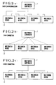
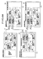
- Figs. 2(a) to 2(c) show the physical connection configurations required to form a bi-directional communication path between the multimedia controller 1 and each of the multimedia devices 2.
- Fig. 2(a) shows the daisy chain connection system adopted in SCSI bus systems (ANSI X3.131-1986)
- Fig. 2(b) shows the star connection system adopted in Ethernet (IEEE 802.3) 10base-T
- Fig. 2(c) shows the series connection system adopted in Ethernet 10Base-2/10base-5.
- the mixed systems shown in Figs. 2(a) to 2(c), such as GPIB (IEEE 488), are known, or the mixed systems shown in Figs. 2(b) and 2(c) are adopted for Ethernet as well.
- communication systems it is possible to select various systems or combinations, such as a system employing optical cables and ISDN.
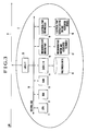
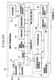
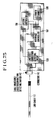
- Fig. 3 is a block diagram showing the internal hardware construction of a general multimedia device.
- a plurality of multimedia devices are connected to a multimedia controller by a LAN 4. Since the LAN 4 is Ethernet, an interface part 20 is provided for processing the communications protocol (TCP/IP) of the LAN 4.
- the interface part 20 can be implemented by using a dedicated LSI or the like.
- the interface part 20 takes out a received message itself or sends a message to the multimedia controller 1.
- a general form of message is expressed as follows: [target_object method_name: parameter]
- the following items are specified:
- the multimedia device 2 shown in Fig. 3 includes an internal bus 10, a CPU 11 for executing all the software processes and hardware controls, a ROM 12 in which programs, initial values and unique information are stored in advance, a RAM 13 in which to temporarily store data or internal parameters such as the state of the device or which is to be used as a work area during execution of a program, a data I/O 14 for accessing multimedia data 15 stored in an internal or external medium, a mechanism-part driving part 16 for controlling a mechanism part 17 such as a motor, and an electrical-part driving part 18 for controlling an electrical part 19 such as a switch SW or a display system including an LED and others.
- the CPU 11, the ROM 12, the RAM 13, the data I/O 14, the mechanism-part driving part 16 and the electrical-part driving part 18 are interconnected via the internal bus 10.
- the multimedia data 15 includes digital data, such as image, sound and texts, which are stored in a particular portion which can take various forms, for example, an optical disk such as a CD-ROM or an MD, or a magnetic tape medium such as a DCC or a DAT, or a semiconductor memory card.
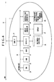
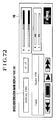
- Fig. 4 is a block diagram showing the internal hardware construction of the multimedia controller 1.
- the multimedia controller 1 is connected to the multimedia devices 2 by the LAN 4. Since the LAN 4 is Ethernet, an interface part 31 is provided for processing the communications protocol (TCP/IP) of the LAN 4.
- the interface part 31 can be implemented by using a dedicated LSI or the like. The interface part 31 takes out a received message itself or sends a message to a desired one of the multimedia devices 2.
- the multimedia controller 1 shown in Fig. 4 includes an internal bus 30, a CPU 21 for executing all the software processes and hardware controls, a ROM 22 in which programs, initial values and unique information are stored in advance, a RAM 23 in which to temporarily store data or internal parameters such as the state of the device or which is to be used as a work area during execution of a program, a multimedia filing device 25 for executing processes, such as storage, retrieval, play (reproduction) and editing, of multimedia data with respect to either of an internal medium and an external medium, a data I/O 24 for executing access control of the multimedia filing device 25, an electrical-part driving part 28 for controlling an electrical part 29 such as a switch SW or a display system including an LED and others, a display controller 26 for executing display control of a display 27 which constitutes a man-machine interface, and a pointing device (not shown) such as a mouse.
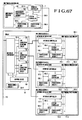
- Fig. 6 is a system hierarchical chart of the software of the multimedia device 2.
- the internal block diagram shown in Fig. 3 corresponds to hardware 57, and an OS 58 is provided for executing basic control for controlling the hardware 57.
- the kind of the OS 58 is not limited to a particular OS, it is desirable to select an OS which has both a real-time processing feature and a multitasking function capable of simultaneously executing a plurality of programs in parallel.
- a class library 59 unique to the multimedia device 2 is provided above the OS 58.
- the system hierarchy also includes a library associated with a control panel of the multimedia device 2 itself as well as control to be executed on the multimedia device 2, which library allows the multimedia device 2 itself to be controlled by the multimedia controller 1. While the multimedia device 2 is connected to the multimedia controller 1, control unique to the multimedia device 2 can be executed by the multimedia controller 1 by transmitting the library to the multimedia controller 1.
- a C function 60 is provided for executing a timer operation and an arithmetic operation.
- the uppermost layer of the system hierarchy is occupied by application software 61 which serves to execute control of the multimedia device 2 itself and communications with the multimedia controller 1 as well as providing a user interface.
- the application software 61 can serve to execute various controls of the multimedia device 2 itself by exchanging massages with the multimedia controller 1, and internal parameters can be read out or modified as instance variables.
- Fig. 5 is a system hierarchical chart of the software of the multimedia controller 1.
- the internal block diagram shown in Fig. 4 corresponds to hardware 50, and an OS 51 is provided for executing basic control for controlling the hardware 50.
- the kind of the OS 51 is not limited to a particular OS, it is desirable to select an OS which has both a real-time processing feature and a multitasking function capable of simultaneously executing a plurality of programs in parallel.
- a window server 52 is provided above the OS 51 for executing GUI (Graphical Users Interface) events, such as display of a control picture for a plurality of connected multimedia devices 2, display of the state of the entire system connection, and switching of controls or switching between data input and data output.
- GUI Graphic User Interface
- a common class library 53 stores a group of basic and common components (a group of objects) associated with a user interface or control, such as button, slide volume and text display area, the components being prepared in the multimedia controller 1 in advance.
- a unique class library 55 stores a group of components (a group of objects) associated with a panel display or control unique to a corresponding one of the connected multimedia devices 2. As described previously, the number of unique class libraries 55 increases each time another multimedia device is connected to the system and sends its unique class library to the multimedia controller 1. Specific procedures for sending such a unique class library will be described later.
- a C function 54 is provided for executing a timer operation and an arithmetic operation.
- the uppermost layer of the system hierarchy is occupied by application software 56 which serves to execute control of the entire connected multimedia device 2 and communications with the multimedia device 2 as well as providing a user interface.
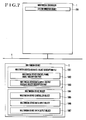
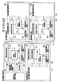
- Fig. 7 is a view showing a state in which the multimedia device 2 has not yet been connected to the multimedia controller 1.
- digital data is communicated by the LAN 4, and the multimedia controller 1 controls the operation of the entire system.
- the multimedia device 2 to be connected to the LAN 4 has a structure generalized as shown in Fig. 7.
- a system director object 205 is a software object (hereinafter referred to as "object") which is resident in the multimedia controller 1 and performs management of the entire system.
- a multimedia device object 1064 is an object which functions as a multimedia device which is identified as an object by the other objects provided on the LAN 4.
- the multimedia device object 1064 includes three objects 1065, 1066 and 1067.
- the object 1065 is a multimedia device controller object for executing control of hardware to realize a greater part of the functions of the multimedia device 2.
- the object 1066 is a multimedia device data input object which serves to receive digital data inputted from another device via the LAN 4.
- the object 1067 is a multimedia device data output object which serves to output digital data to another device via the LAN 4.
- Reference numeral 1061 denotes a multimedia device delegate object description file which describes the specifications of a multimedia device delegate object generated in the multimedia controller 1 when the multimedia device 2 is connected to the multimedia controller 1 via the LAN 4.
- the multimedia device delegate object description file 1061 includes a multimedia device control panel object description part 1062 which describes the specifications of a manipulation panel for the multimedia device 2 and a data input/output delegate object description part 1063 which describes the specifications of a data input/output delegate object which serves as a delegate to input or output data to or from the multimedia device 2.
- the multimedia device control panel object description part 1062 realizes the function of a GUI description language which describes a control panel to be used for manipulating the multimedia device 2 through a GUI.
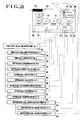
- Fig. 8 is a view showing a state in which the multimedia device 2 is connected to the LAN 4.
- a multimedia device delegate object 1068 is generated in the multimedia controller 1 and functions as the delegate of the multimedia device 2 in the multimedia controller 1.
- the multimedia device delegate object 1068 includes a multimedia device control panel object 1069 which functions as a control panel of the multimedia device 2, a multimedia device data input delegate object 1070 which functions as the delegate of the multimedia device data input object 1066 during inputting of data, and a multimedia device data output delegate object 1071 which functions as the delegate of the multimedia device data output object 1067.
- Fig. 9 is a view showing the construction of a general class library.
- a first class 1079 is a class which functions as a template for generating objects for defining the nature or function common to objects having similar natures.
- a class library 1086 includes p classes, i.e., the first class 1079 to a p -th class 1085, and each object belongs to a particular one of the classes.
- a class definition part 1080 defines the data types and the names of internal variables of objects which belong to the class 1079, as well as the data types and the names of internal functions (generally called "class method") representative of data processing means.
- a class method table 1081 contains pointers to individual codes of the class method in the form of a table to enable access to the class method.
- a code part 1082 stores k function codes of the class method which include a first function code 1083 to a k -th function code 1084.
- Fig. 10 is a view showing the structure of a general object.
- an object 234 includes a pointer-to-class-method-table storage part 244, message communicating means 245, processing retrieving means 246, a method part 239 and an internal data part 235.
- the method part 239 includes m data processing means, i.e., first data processing means 240, second data processing means 241, ..., m -th data processing means 242.
- An internal data part 235 includes n internal data, i.e., first internal data 236, second internal data 237, ..., n -th internal data 238.
- the data processing means 240, 241, ..., 242 which constitute the method part 239 can be shared by objects which belong to the same class, the data processing means of from the first data processing means 240 to the m -th data processing means 242 are managed for each class by the class method table 243 and shared by a plurality of objects which belong to the same class.
- the class method table 243 is referred to by each of the objects by means of the pointers stored in the pointer-to-class-method-table storage part 244.
- the message communicating means 245 receives a message from another object and sends it to the processing retrieving means 246.
- the processing retrieving means 246 analyzes the message, retrieves data processing means which corresponds to the message from the method part 239 (actually, the class method table 243), and causes the retrieved data processing means to execute data processing.
- the data processing means executes predetermined processing of the data added to the message, internal data present in the internal data part 235 and external data. In the case of processing which needs to send a message to another object, the message is sent out to the desired object by means of the message communicating means 245.
- Fig. 11 is a view showing the structure of the system director object 205.
- the system director object 205 shown in Fig. 11 includes a pointer-to-class-method-table storage part 1072 which stores pointers to a system director class class method table 1073, multimedia device delegate object generating means 1047 for generating the multimedia device delegate object 1068 (refer to Fig. 8) on the basis of the description of the multimedia device delegate object description file 1061, data input/output managing means 343 for managing inputting and outputting of data between objects, application object generating means 380 for generating application objects for various purposes, message communicating means 1074, processing retrieving means 342, a method part 1075, and an internal data part 1076.
- the internal data part 1076 includes an object ID 1077, device-to-device link information management data 344 to be used for causing a plurality of multimedia devices to perform a particular operation, and object registration information 1078 about connected multimedia devices and generated objects.
- the system director object 205 reads the multimedia device delegate object description file 1061 by using the multimedia device delegate object generating means 1047, selects a class to which an object to be generated belongs, from the information described in the multimedia device delegate object description file 1061, and generates the multimedia device delegate object 1068 on the basis of the class definition part 1080 of the selected class in the class library 1086.
- Fig. 12 is a view showing the construction of the control panel description part of a delegate object description file.
- a control panel object description part 247 includes i pieces of object description information, i.e., first object description information 248 to an i -th object description information 249.
- One piece of object description information includes object recognition information 250, object graphical-display information 254 and object link information 260.
- the object recognition information 250 includes a class name 251 indicative of a class to which the corresponding object belongs, an object ID 252 which is an ID unique to an i -th object, and an object ID 253 indicative of the ID of an object to which the i -th object directly belongs.
- the object graphic information 254 is information to be used for graphically displaying objects, such as buttons which constitute part of a control panel display picture 231, and includes j pieces of object graphic information, i.e., first object graphic information 255 to j -th object graphic information 259.
- One piece of object graphic information includes graphical-display position and size information 256, shape and color information 257 and an object image 258.
- the object link information 260 includes a description which provides link information about a link between an object, such as a digital VTR controller object 207, which constitutes a control panel object and an object to which such an object corresponds.
- the object link information 260 includes k pieces of object link information, i.e., first object link information 261 to k -th object link information 264.
- One piece of object link information includes a corresponding object ID 262 and a sending message 263 to be sent out to a corresponding object.
- Fig. 13 shows the construction of a data input/output delegate object description part of the delegate object description file.
- a data input/output delegate object description part 650 includes first input delegate object information 651, ..., m -th input delegate object information 655.
- Each of the input delegate object information 651 to 655 includes an object ID 652 of its own, a link-target corresponding data input object ID 653 indicative of the ID of a data input object to be linked, and an acceptable file type list 654 which is a list of file types which can be inputted.
- the data input/output delegate object description part 650 also includes first output delegate information 659, ..., n -th output delegate object information 663.
- Each of the output delegate object information 659 to 663 includes an object ID 660 of its own, a corresponding data output object ID 661 indicative of the ID of a corresponding data output object, and an acceptable file type list 662 which is a list of file types which can be outputted.
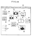
- Fig. 14 is a view showing a state in which a digital VTR represented as an object has not yet been connected to the multimedia controller 1.
- reference numeral 203 denotes the digital VTR
- a digital VTR object 206 is resident in the digital VTR 203 and functions as a digital VTR which is identified as an object by the other multimedia devices provided on the LAN 4.
- the digital VTR object 206 includes three objects.
- a digital VTR controller object 207 executes hardware control of the digital VTR 203.
- a digital VTR data input object 208 serves to receive digital data inputted from another multimedia device via the LAN 4.
- a digital VTR data output object 209 serves to output digital data to another multimedia device via the LAN 4.
- a digital VTR delegate object description file 210 describes the specifications of a digital VTR delegate object generated in the multimedia controller 1 when the digital VTR 203 is connected to the multimedia controller 1 via the LAN 4.
- the digital VTR delegate object description file 210 includes a digital VTR control panel object description part 211 which describes the specifications of a manipulation panel for the digital VTR 203 and a digital VTR data input/output delegate object description part 212 which describes the specifications of a digital VTR data input/output delegate object which serves as a delegate to input or output data to or from the digital VTR 203.
- Fig. 15 is a view showing the structure of the digital VTR controller object 207.
- a pointer-to-class-method-table storage part 1009 stores pointers to a class method table 1018.
- the class method table 1018 includes a multiplicity of data processing means such as play executing means 1019 for controlling the hardware of the digital VTR 203 executing and executing a playback operation and recording executing means 1020 for executing a recording operation.
- the digital VTR controller object 207 also includes message communicating means 1010, processing retrieving means 1011, a method part 1012 and an internal data part 1015.
- a control class class method table 1018 contains actual data processing means to be executed by the method part 1012.
- the internal data part 1015 includes a multiplicity of variables and status information, such as a tape running state 1016 and a current tape position 1017, which are needed to control the digital VTR 203.
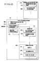
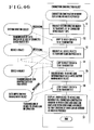
- Fig. 16 is a flowchart showing the flow of the operation to be executed when the digital VTR 203 is connected to the LAN 4.
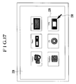
- Fig. 17 is a diagrammatic view showing a picture of the multimedia controller 1.
- reference numeral 228 denotes a display picture of the multimedia controller 1
- reference numeral 229 denotes an icon display indicating that the digital VTR 203 is connected
- reference numeral 230 denotes a cursor indicating a position indicated by a pointing device such as a mouse.
- the pointing device has a button, and the operation of pressing and releasing the button is generally called “click” and the operation of repeating the click twice at a predetermined interval is generally called “double-click”.
- a camera still image input device
- a tuner tuner
- a television set various databases
- a CD and other multimedia devices are connectable to the multimedia controller 1, and selection and control of such multimedia devices can be performed through icon displays on the display picture 228.
- Fig. 18 is a view showing a state in which the digital VTR 203, which is one example of the multimedia devices 2, is connected to the LAN 4.
- a digital VTR delegate object 220 is generated in the multimedia controller 1 when the digital VTR 203 is connected to the LAN 4, and functions as the delegate of the digital VTR 203 in the multimedia controller 1.
- the digital VTR delegate object 220 includes a digital VTR control panel object 221 which functions as a control panel of the digital VTR 203, a digital VTR data input delegate object 222 which functions as the delegate of the digital VTR data input object 208 during inputting of data, and a digital VTR data output delegate object 223 which functions as the delegate of the digital VTR data output object 209.
- Step 636 An operation to be executed when the digital VTR 203, which is one example of the multimedia devices 2, is connected to the LAN 4 will be described below with reference to Figs. 16, 17 and 18.
- the system director object 205 recognizes the connection to the digital VTR 203 (Step 637). Then, the system director object 205 sends a device ID to the digital VTR 203 (Step 638).
- the system director object 205 loads the digital VTR delegate object description file 210 from the digital VTR 203 by using the multimedia device delegate object generating means 1047 (Step 639). Then, the system director object 205 generates the digital VTR delegate object 220 in the multimedia controller 1 on the basis of the digital VTR delegate object description file 210 by using the multimedia device delegate object generating means 1047 (Step 640). The resultant state of connection is shown in Fig. 18. Then, the digital VTR delegate object 220 displays the icon display 229 of the digital VTR 203 on the display picture 228 of the multimedia controller 1 (Step 641). Subsequently, the digital VTR delegate object 220 waits for an instruction to be inputted by a user (Step 642).
- the user can the digital VTR 203 via the digital VTR delegate object 220 provided in the multimedia controller 1 by manipulating the digital VTR 203 on the basis of the manipulation picture displayed on the basis of the digital VTR control panel object 221 of the multimedia controller 1.
- Fig. 19 is a view showing the icon display of the digital VTR 203
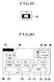
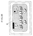
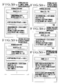
- Fig. 20 is a view showing one example of a control panel display picture.
- Fig. 19 shows the icon display 229 to be displayed when the digital VTR 203 is connected to the LAN 4.
- Fig. 20 shows a default display picture graphically displayed by the digital VTR control panel object 221.
- the default display picture includes a control panel display selecting menu 232 displayed on the display picture, a time counter display 265 for indicating the elapsed time of tape, a control mode selecting part 266 for selecting a control mode of the digital VTR 203, a first switch button display 267 for selecting a default control mode, a second switch button display 268 for selecting a detailed control mode, a rewinding button display 269, a reverse play button display 270, a pause button display 271, a play button display 272, a fast forward feed button display 273, a stop button display 274 and a recording button display 275.
- Fig. 21 is a view showing the correspondence between the classes to which individual objects belong and the constituent elements of the digital VTR control panel object 221.
- the classes to which the respective basic constituent elements belong are defined in the class library 1081 (refer to Fig. 9) in advance, and are held in the multimedia controller 1.
- the individual constituent elements of the digital VTR control panel object 221 functions as objects which constitute the digital VTR control panel object 221.
- the generation of the play button object 290 which is one of the objects constituting the digital VTR control panel object 221 will be described below by way of example.
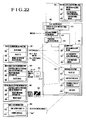
- Fig. 22 is an explanatory view showing the generation of the play button object 290.
- reference numerals 297, 298, 299, 300, 601, 602, 603, 604, 605, 606, 607, 608, 609, 610 and 611 denote the elements described in the control panel object description part 247 of the digital VTR delegate object description file 210.
- the object recognition information 297 includes the class name 298, the object ID 299 and the object ID 300 of an object to which the play button object 290 belongs.
- the first object graphical-display information 601 includes the graphical-display position and size information 602, the shape and color information 603 and the object image 604.
- the second object graphical-display information 605 includes the graphical-display position and size information 606, the shape and color information 607 and the object image 608.
- the object link information 609 includes the link target object ID 610 and the sending message 611.
- the play button object 290 is generated from the button class and the information described in the control panel object description part 247 of the digital VTR delegate object description file 210.
- a pointer-to-class-method-table storage part 613 stores pointers which point to a button class class method table 625.
- the button class class method table 625 includes button initializing means 626 for initializing the internal variables of a button object when an object of the button class is to be generated, button graphic displaying means 627 for graphically displaying the play button object 290, and click response means 628.
- the click response means 628 responds to the click operation to indicates that the play button object 290 has been clicked, as by temporarily changing the state of a button display, and sends a message to another object.
- the definitions of these respective data processing means which are held on the button class class method table 625 are described in a class, and are referred to and used in common by not only the play button object 290 but also all the objects which belong to the other button classes.
- the play button object 290 includes message communicating means 614 and processing retrieving means 615.
- the play button object 290 also includes a method part 616 and an internal data part 620.
- the internal data part 620 includes an object ID 621, button state data 622, a graphical-display parameter 623 and link data 624.
- the types of internal data to be possessed by not only the play button object 290 but also all the button objects which belong to the button class are described in a class.
- the system director object 205 reads the digital VTR delegate object description file 210 to generate the individual objects.
- the system director object 205 generates the objects of the button class on the basis of the description of the class name 298 of the object recognition information 297. If the system director object 205 is to generate the digital VTR data output object 209, the internal data part 620 is initialized by the button initializing means 626.
- the system director object 205 understands an object-to-object relationship representing which object belongs to which object, and generates an object made up of a plurality of objects in the form of a composite object.
- the button graphic displaying means 627 graphically displays the play button object 290 on the basis of the graphical-display parameter 623 and the button state data 622.
- the button graphic displaying means 627 is automatically executed when a button object is to be generated and when an object to which an object belongs is moved.
- the first object graphical-display information 601 describes graphical-display information 629 indicative of the play button which is not pressed.
- the graphical-display position and size information 602 describes rectangular-frame information indicative of the graphical-display position and the size of the play button object 290 in the digital VTR control panel object 221.
- the rectangular-frame information is defined by coordinate information relative to the coordinate system of the digital VTR control panel object 221, and is represented by, for example, the coordinates of a top-left point and those of a right-bottom point such as (X1, Y1) and (X2, Y2) of the graphical-display information 629 indicative of the play button which is not pressed.
- Graphical display of the play button which is not pressed is provided on the basis of either the shape and color information 603 or the object image 604.
- the shape and color information 603 is described in a language which serves to graphically display an object, such as the way of drawing lines and the way of painting colors.
- the object image 604 is represented as bit-map data. In general, the shape and color information 603 using such a language does not need a large amount of data, but the object image 604 using the bit-map data provides great flexibility.
- the second object graphical-display information 605 describes graphical-display information 630 indicative of the play button which is pressed, in a manner similar to the first object graphical-display information 601.
- a graphical-display parameter 623 is determined on the basis of the first object graphical-display information 601 and the second object graphical-display information 605.
- the link data 624 is set on the basis of the object link information 609, and "PLAY" is set as a sending message and a link target object ID is set as the link target object ID 610.
- the device ID which is assigned to the digital VTR 203 by the system director object 205 when the digital VTR 203 is connected to the LAN 4, is added to the link target object ID 610.
- the button state data 622 holds state data indicating whether the play button is pressed.
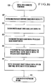
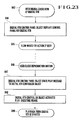
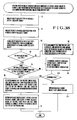
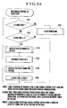
- Fig. 23 is a view showing the flowchart of an operation to be executed when a user places the cursor 230 on the icon display 229 of the digital VTR 203 and double-clicks the icon display 229, as well as the flowchart of an operation to be executed when the user manipulates the control panel of the digital VTR 203.
- Fig. 24 is a view showing a display picture of the multimedia controller 1 to be displayed when the user double-clicks the icon display 229 of the digital VTR 203.
- the control panel display picture 231 of the digital VTR 203 is displayed as a default control display picture, and the play button display 272 is displayed as shown.
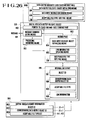
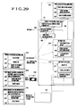
- Fig. 29 is a view showing the structure of the digital VTR control panel object which belongs to the panel class as well as the relationship between the structure and object description information.
- the digital VTR control panel object 221 includes a pointer-to-class-method-table storage part 1401 which stores pointers to a panel class class method table 1402.
- the panel class class method table 1402 includes panel initializing means 1403 for initializing a panel object, panel graphic displaying means 1404 for graphically displaying a panel, and click response means 1405 for displaying a click response operation when the panel is double-clicked.
- the digital VTR control panel object 221 also includes message communicating means 1406, processing retrieving means 1407 and internal data part 1410.
- the internal data part 1410 includes an object ID 1411, panel state data 1412 and a graphical-display parameter 1413.
- the internal data part 1410 is initialized in accordance with the description of the digital VTR delegate object description file 210.
- the digital VTR control panel object description part 211 of the digital VTR delegate object description file 210 includes object recognition information 1414, first object graphic information 1418 indicative of an icon image 1426 of the digital VTR 203, and second object graphic information 1422 indicative of a frame 1427 of the control panel of the digital VTR 203.
- the first object graphic information 1418 includes graphical-display position and size information 1419, the shape and color information 1420, and an object image 1421.
- the second object graphic information 1422 includes graphical-display position and size information 1423, shape and color information 1424, and an object image 1425.
- the digital VTR delegate object 220 displays the icon display 229 on the basis of the icon image 1426. If the user double-clicks the icon display 229 of the digital VTR 203 while placing the cursor 230 on the icon display 229 (Step 643), the digital VTR control panel object 221 of the digital VTR delegate object 220 sends messages to all the objects which constitute the digital VTR control panel object 221, thereby instructing all the objects to execute the respective graphical displays. All the objects shown in Fig.
- Step 644 the digital VTR control panel object 221 graphically displays the frame of the control panel of the digital VTR 203 on the basis of the second object graphic information 1422.
- the digital VTR control panel display picture 231 for manipulating the digital VTR 203 is displayed as shown in Fig. 24 (Step 644), and the flow waits for an instruction to be given by the user (Step 645).
- Step 645 the digital VTR control panel object 221 sends the massage "PLAY" to a controller object 214 of the digital VTR 203 (Step 647).
- the controller object 214 of the digital VTR 203 activates play executing means in response to the message (Step 648).
- the play operation of the digital VTR 203 is started (Step 649).
- the multimedia device delegate object required to manipulate the multimedia device is automatically generated in the multimedia controller.
- the control panel required to manipulate the multimedia device is automatically displayed on the display picture of the multimedia controller, and if a user manipulates the control panel, an appropriate message is sent to a controller object of the multimedia device so that a desired manipulation can be performed.
- the information required to generate the multimedia device delegate object required to manipulate the multimedia device is obtained from a multimedia device delegate object description file read from the multimedia device. Accordingly, the multimedia controller needs only to have a basic class library, and does not need to have information about a specific multimedia device.
- Fig. 25 is a view showing the structure of the digital VTR data input delegate object as well as the relationship between the structure and object description information.
- the digital VTR data input delegate object 222 shown in Fig. 25 includes a pointer-to-class-method-table storage part 668 which store pointers to a data input delegate class class method table 679.
- the data input delegate class class method table 679 includes data input delegate object initializing means 680, link information updating means 681 and acceptable file type replying means 678.
- the digital VTR data input delegate object 222 also includes message communicating means 669, processing retrieving means 670 and a method part 671.
- An internal data part 674 includes an object ID 675, corresponding data input object ID 676 indicative of the ID of a corresponding data input object, an acceptable file type 677 indicative of the file types of data which can be inputted, link information 1006 indicative of a link to a data output object.
- the digital VTR data input delegate object 222 is generated on the basis of the digital VTR data input/output delegate object description part 212 of the digital VTR delegate object description file 210.
- the data input delegate object initializing means 680 initializes the data of the internal data part 674 in accordance with the descriptions of the input delegate object information 682.
- Fig. 26 is a view showing the structure of the digital VTR data output delegate object as well as the relationship between the structure and object description information.
- the digital VTR data output delegate object 223 shown in Fig. 26 includes a pointer-to-class-method-table storage part 690 which stores pointers to a data output delegate class class method table 1048.
- the data output delegate class class method table 1048 includes data input delegate object initializing means 694, data input instruction sending means 695 and acceptable file type replying means 700.
- the digital VTR data output delegate object 223 also includes message communicating means 691, processing retrieving means 692, a method part 693 and an internal data part 696.
- the internal data part 696 includes an object ID 697, a corresponding data output object ID 698 which is the ID of a corresponding data output object ID, an acceptable file type 699 indicative of the file types of data which can be inputted, and link information 688 indicative of a link to an data output object.
- the digital VTR data output delegate object 223 is generated on the basis of the digital VTR data input/output delegate object description part 212 of the digital VTR delegate object description file 210.
- the data output delegate object initializing means 694 initializes the data of the internal data part 696 in accordance with the description of the output delegate object information 1001.
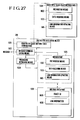
- Fig. 27 is a view showing the structure of the digital VTR data input object.
- the digital VTR data input object 208 shown in Fig. 27 includes a pointer-to-class-method-table storage part 1022 which stores pointers to a data input class class method table 1031.
- the data input class class method table 1031 includes file writing means 1032, data receiving means 1033 and link information updating means 686.
- the digital VTR data input object 208 also includes message communicating means 1023, processing retrieving means 1024, a method part 1025 and an internal data part 1028.
- the internal data part 1028 includes an object ID 1029 and link information 1030.
- Fig. 28 is a view showing the structure of the digital VTR data output object.
- the digital VTR data output object 209 shown in Fig. 28 includes a pointer-to-class-method-table storage part 1035 which store pointers to a data output class class method table 1044.
- the data output class class method table 1044 includes data reading means 1045, data transmitting means 1046 and link information updating means 687.
- the digital VTR data output object 209 includes message communicating means 1036, processing retrieving means 1037, a method part 1038 and an internal data part 1041.
- the internal data part 1041 includes an object ID 1042 and link information 1043.
- the digital VTR data input delegate object 222 and the digital VTR data output delegate object 223 of the digital VTR 203 function as if they were the digital VTR data input object 208 and digital VTR data output object 209.
- the system director object 205 inquires the types of files which can be inputted of the digital VTR data input delegate object 222.
- the acceptable file type replying means 678 of the digital VTR data input delegate object 222 replies the file types which can be received by the digital VTR 203.
- a link is set to connect the output delegate object of a multimedia device having the file to be copied to the digital VTR data input delegate object 222.
- the link information updating means 681 of the digital VTR data input delegate object 222 sends a message to the digital VTR data input object 208 and activates the link information updating means 686 of the digital VTR data input object 208, and the link information updating means 686 updates the link information 1030 of the digital VTR data input object 208.
- the data output delegate object of the multimedia device having the file to be copied sends a message for updating the link information of the data output object, whereby the link information is updated.
- a link is set between the data output object of the multimedia device having the file to be copied and the digital VTR data input object 208.
- the data transmitting means of the data output object of the multimedia device having the file to be copied is activated, and the data output object of the multimedia device having the file to be copied sends a message to the digital VTR input object.
- the data receiving means 1033 and the file writing means 1032 are activated to perform copying of the file.
- the data input delegate object and the data output delegate object respectively send messages to the data input object and the data output object in each of the desired multimedia devices, thereby setting a data link between the multimedia devices. Accordingly, the multimedia controller does not need to directly participate in an actual, data copying process or the like.
- the software required to perform such control does not need to be installed or prepared in the multimedia controller in advance.
- a desired multimedia device is connected to a LAN, a corresponding control panel and the state of the connected multimedia device are displayed on the display of the multimedia controller, whereby it is possible to achieve great advantages; for example, on the picture, it is possible to easily turn on and off a power source, to control the multimedia device, and to execute switching between input and output.
- some of the components of a control panel sent from a multimedia device to the multimedia controller can be replaced with components having identical definitions and provided in the multimedia controller in advance, to a user's taste. Accordingly, it is possible to unify various user interfaces which differ among manufacturers.
- control by a distant multimedia controller and access to multimedia devices can be transparently executed via a LAN.
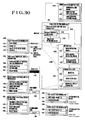
- Fig. 30 is a view showing the structure of the panel view setting menu object as well as the relationship between the structure and object description information.
- the panel view setting menu object 285 shown in Fig. 30 includes a pointer-to-class-method-table storage part 1428 which stores pointers to a menu class class method table 1430.
- the menu class class method table 1430 includes menu initializing means for initializing a menu object, menu graphic displaying means 1432 for graphically displaying a menu, and menu selection response means 1433 for displaying a response operation when a selection from the menu is performed.
- the panel view setting menu object 285 also includes message communicating means 1429, processing retrieving means 1434, a method part 1435 and an internal data part 1436.
- the internal data part 1436 includes an object ID 1437, menu state data 1438 and a graphical-display parameter 1439.
- the internal data part 1436 is initialized in accordance with the digital VTR delegate object description file 210, and the panel view setting menu description part of the digital VTR control panel object description part 211 of the digital VTR delegate object description file 210 includes object recognition information 1440, first object graphical-display information 1444 for displaying the title of a panel view setting menu, second object graphical-display information 1448 for displaying a first menu item of the panel view setting menu, and third object graphical-display information 1452 for displaying a second menu item of the panel view setting menu.
- the first object graphical-display information 1444 includes graphical-display position and size information 1445, shape and color information 1446 and an object image 1447, and represents a menu title 1462.
- the second object graphical-display information 1448 includes graphical-display position and size information 1449, shape and color information 1450 and an object image 1451, and represents a first menu item 1463.
- the third object graphical-display information 1452 includes graphical-display position and size information 1453, shape and color information 1454 and an object image 1455, and represents a second menu item 1464.
- First object link information 1456 describes a message to be issued when the first menu item 1463 is selected as well as a receiver to which the message is to be sent.
- the link target object ID 1457 is the ID of the system director object 205, and a sending message 1458 represents the message "Create object with file "Default"”.
- Second object link information 1459 describes a message to be issued when the second menu item 1464 is selected as well as a receiver to which the message is to be sent.
- An link target object ID 1460 represents the ID of the system director object 205, and a sending message 1461 represents the message "Create object with file "Custom1"".
- Fig. 31 is an explanatory view showing that the system director object 205 has the function of selecting one file from a plurality of files when the system director object 205 is to read a multimedia device delegate object description file.
- reference numeral 1465 denotes a digital VTR delegate object description file named "Default”
- reference numeral 1466 denotes a digital VTR delegate object description file named "Custom1”.
- Fig. 32 is a view showing the way in which a user switches the control panel.
- Fig. 33 is a view showing a picture which appears after the switching of the control panel.
- the system director object 205 reads the digital VTR delegate object description file 1465 named "Default" and generates the digital VTR control panel object 221, the digital VTR control panel display picture 231 is displayed in its default state and the panel view setting menu 232 is set to "Default". If a user selects "Custom1" of the panel view setting menu 232 with the cursor 230 of the pointing device, the panel view setting menu object 285 sends the message "Create object with file "Custom1"" to the system director object 205 by the menu selection response means 1433. In response to the message, the system director object 205 discards and regenerates the digital VTR delegate object 220 through the multimedia device delegate object generating means 1047.
- the system director object 205 reads the digital VTR delegate object description file 1466 named "Custom1" and regenerates the digital VTR control panel object 221 on the basis of the digital VTR delegate object description file 1466.
- a control panel which is apparently different from the digital VTR delegate object description file 1465 named "Default” is written into the digital VTR delegate object description file 1466 named "Custom1", whereby it is possible to display an apparent, second control panel display picture 233 as shown in Fig. 33 by way of example.
- Figs. 34(a) and 34(b) are views showing different examples of the arrangement of manipulating buttons.
- the arrangements of manipulating buttons of electrical equipments as well as multimedia devices differ among manufacturers, and may even differ among products manufactured by a single manufacturer. This fact confuses users. If a user who is familiarized with the manipulation of a particular device purchases a new device, the user needs to learn the manipulation of the new device.
- application software which allows a user to modify the arrangement of manipulating buttons through an interactive manipulation and causes a delegate object description file to reflect the result of the modification, users become able to freely customize control panels to their tastes.
- a company or a third party which provides the multimedia controller 1
- provides various multimedia device delegate object description files the arrangements of manipulating buttons of multimedia devices which differ among individual companies, for example, the arrangement of Fig. 34(a) adopted by a company A and the arrangement of Fig. 34(b) adopted by a company B, can be unified in accordance with the policy of the company or the third party which provides the multimedia controller 1.
- An increase in the functional level of multimedia devices is another cause of the confusion of users. Specifically, if manipulating members for functions which are normally not used by ordinary users or which can only be used by users having technical knowledge are displayed on a control panel, the ordinary users may become unable to easily use multimedia devices. To solve such a problem, the present invention also makes it possible to display only the manipulating members needed by a user.
- Fig. 35 shows the control panel display picture of a digital VTR having high-level functions.
- a control panel display picture 276 to be used for manipulating functions which contain additional functions includes sliders 277 and 280 for manually adjusting sound recording levels, respectively, and level meters 278 and 279 for monitoring the respective sound recording levels.
- a button group 281 for setting a desired image compression mode includes a default compression mode setting button 282 and an MPEG (an internationally standardized, moving-image compression system) compression mode setting button 283. These manipulating members merely confuse users who do not need such high-level functions.
- MPEG an internationally standardized, moving-image compression system
- control panel display picture 231 for manipulating only the minimum required functions and the control panel display picture 276 for manipulating functions which containing additional functions
- the control mode switching object 294 it is possible to perform switching between the control panel display picture 231 for manipulating only the minimum required functions and the control panel display picture 276 for manipulating functions which containing additional functions, by means of the control mode switching object 294.
- the system director object 205 reads a digital VTR control panel delegate object description file which describes the control panel display picture 276 for manipulating the functions which contains the additional functions, to generate a control panel object for manipulating the functions which contains the additional functions.
- the user similarly selects the default button 267 shown in Fig. 35 by using the pointing device, so that the system director object 205 reads a digital VTR control panel delegate object description file which describes the control panel display picture 231 for manipulating the minimum required functions, to regenerate a control panel object for manipulating the minimum required functions.
- a plurality of multimedia device delegate object description files are employed for selecting a plurality of GUIs.
- the second embodiment is intended to provide an environment which makes it possible to transparently use multimedia devices in a common manner through a controller via a LAN without the need for special software such as application software or a device driver. Further, the second embodiment is intended to make it possible to construct, for communication of data between the multimedia devices, a data sending and receiving relationship between the multimedia devices by means of a user interface which can be easily manipulated by a user, thereby enabling the multimedia devices to communicate data therebetween without passing the data through the controller during an actual data communication.
- a system which comprises a plurality of multimedia devices and a controller for controlling the plurality of multimedia devices.
- the plurality of multimedia devices and the controller are connected to a network in such a manner that the plurality of multimedia devices and the controller can communicate a message and data based on an object-oriented technique between each of the plurality of multimedia devices and the controller via the network.
- the controller includes display means for displaying icons representative of the respective plurality of multimedia devices, and pointing means for forming a link between arbitrary multimedia devices selected from among the plurality of multimedia devices to specify a data input and output relationship between the arbitrary multimedia devices.
- a data sending and receiving relationship between audio-visual devices can be constructed or modified merely by changing the internal data of an object which relates to the construction or modification of the data sending and receiving relationship, without the need to change the physical connection between the audio-visual devices.
- Control programs for individual objects do not need to be prepared in the controller in advance, and control of the objects can be realized merely by connecting the objects to the controller.
- the controller allows a person who actually specifies a desired control to display and manipulate control means sent from a connected object, so that the person can manipulate through a single interface all the audio/visual devices connected to a network.
- Means for managing the connections between the individual devices is provided in the controller, and this managing means uses the display means to display the connection status of each of the devices. Accordingly, even if a multiplicity of connection relationships are constructed, users can easily recognize the statuses of the respective connections.
- messaging to be executed when a user is to copy data from a digital camera to a digital VTR will be specifically described below as a second embodiment. It is assumed here that the digital camera referred to in the description of the second embodiment is of a handy type capable of outdoor recording of moving images and sound and has communication means for communication with the system.
- Fig. 36(a) shows control panels to be displayed on a multimedia controller display.
- Reference numeral 301 denotes a control panel for controlling a digital camera device
- reference numeral 310 denotes a control panel for controlling a digital VTR device.
- Each of the control panels 301 and 310 is displayed on the multimedia controller display by the previously-described multimedia device control panel object description part (1062 in Fig. 7) being read from the corresponding one of the devices into the multimedia controller by a system director, and waits for an event to be specified by the user.
- tape insertion display parts 302 and 311 display whether tapes are inserted in the respective devices.
- Counters 303 and 312 display the running times of the tapes inserted in the respective devices.
- Button objects 304 and 313 are for displaying the lists of the contents of the tapes inserted in the respective devices, and when the button object 304 or 310 is clicked with a mouse, the list of the contents of the tape is displayed.
- a Play button object 305 or 314 is clicked with the mouse, the corresponding device executes a playback operation.
- the corresponding device executes fast forward feeding of the tape.
- the corresponding device executes rewinding of the tape.
- a stop button object 308 or 317 is clicked with the mouse, the corresponding device stops any of the Play, FF, RWD and Rec functions.
- the Rec button object 309 or 318 is clicked with the mouse, the corresponding device starts to record video and audio data inputted from the outside via a communication medium such as a LAN.
- a black frame 319 is displayed as shown in Fig. 36(b). If the user continues the dragging on the control panel 301 and moves the mouse cursor out of the black frame 319, an arrow 321 is displayed to extend in such a manner that the pointing head reaches the position of the mouse cursor. If the user further continues to move the mouse and the mouse cursor enters the inside of the frame of the control panel 310, a black frame 320 is displayed. If the user stops the dragging at this time, a link is formed to extend from the control panel 301 to the control panel 310.
- the multimedia controller determines whether the link is valid or invalid. If the link is invalid, the state of display returns to that shown in Fig. 36(a), whereas if the link is valid, the state shown in Fig. 36(b) is maintained.
- Fig. 37 is a view showing the construction of internal objects of each of a multimedia controller 322, a digital VTR device 338 and a digital camera device 339 as well as the connection status of each of them.
- the objects in each of the multimedia controller 322 and the devices 338 and 339 can communicate messages and data to each other.
- the objects of one of the multimedia controller 322 and the devices 338 and 339 can also communicate messages with the objects which exist in another one of the multimedia controller 322 and the devices 338 and 339, by means of communication means 336, 406 and 407 via a LAN 337.
- Each of the objects shown in Fig. 37 can communicate messages and data with another arbitrary object.
- a system direction object 323 includes a method part having means (data input/output managing means) 324 for determining whether input data and output data match each other when data outputted from one device is inputted to another device.
- a connected device delegate object storage part 335 is a part which stores the delegate object of each device created by connected device delegate object initializing means reading the predetermined information required for initialization from each device connected to the LAN 337 at the time of system activation and at predetermined time intervals.
- the second embodiment is arranged to read initialization information from the digital VTR device 338, the digital camera device 339 and other devices (none of which is shown in Fig. 37) which are connected to the LAN 337, and create a digital VTR delegate object 326, a digital camera delegate object 331 and the objects of the other devices (none of which is shown in Fig. 37).
- a digital VTR data input delegate object 325 has answer means for answering an inquiry about the inputting of data into the digital VTR device 338.
- a digital camera data output delegate object 330 has answer means for answering an inquiry about the outputting of data from the digital camera device 339.
- a digital VTR device controller object 340 controls the hardware of the digital VTR device 338 in response to a message sent from another object.
- a digital camera device controller object 341 controls the hardware of the digital camera device 339 in response to a message sent from another object.
- a digital VTR device data input object 408 has data receiving means capable of receiving data sent to its own object ID.
- a digital camera device data output object 409 has data sending means for adding information, such as a data receiver ID, to data reproduced by a reproducing device provided in a digital camera device (not shown) and sending the resultant data through the communication means 407.
- the communication means 336, 406 and 407 are provided for allowing the multimedia controller 322, the digital VTR device 338 and the digital camera device 339, all of which are connected to the LAN 337, to communicate with one another.
- Fig. 11 shows the structure of the system director object 323.
- the processing retrieving means 342 receives from the window server an information message which indicates that a link is formed between devices by the input of a user, the processing retrieving means 342 activates the data input/output managing means 343.
- the data input/output managing means 343 performs a series of processings for making a decision as to the matching of data between the devices linked by the user.
- Fig. 38 is a flowchart showing the processing procedure of the data input/output managing means. If the user forms a link which extends from a device A to a device B, by means of a user interface such as those shown in Figs. 36(a) and 36(b), the window server sends the system director object (205 in Fig. 11) a message (linked message) which indicates that the link has been formed to extend from the device A to the device B.
- the processing retrieving means (342 in Fig. 11) receives the message and activates the data input/output managing means in the method part.
- Step S1 the data input/output managing means inquires an acceptable file type of the output delegate object of the device A (if there are a plurality of acceptable file types, a list of the acceptable file types is replied).
- Step S2 the data input/output managing means inquires an acceptable file type of the input delegate object of the device B. If there are a plurality of acceptable file types (acceptable formats) for the device B, the input delegate object of the device B sends information indicative of the priority of each of the file types to the data input/output managing means.
- the priority indicates the order of file types which can be suitably inputted into the device B, the order being specified by the manufacturer of the device B or the user.
- a file type of highest priority is herein referred to as the "highest-priority file type for the device B".
- Step S3 an acceptable file type (or an acceptable file type list) for the device A is searched for in accordance with the priority of the device B.
- a highest-priority file type for the device B is searched for from among the acceptable file types for the device A which have been read in Step S1.
- the file type which has been obtained through this processing is hereinafter referred to as an optimally acceptable file type for the device A and the device B.
- Step S4 the data input/output managing means fails to search for an acceptable file type in Step S3, i.e., if the same file type does not coexist in the device A acceptable file type list and the device B acceptable file type list, the process proceeds to Step S8. If the data input/output managing means succeeds in searching for the same file type, the process proceeds to Step S5. It is determined in Step S5 whether the data attribute of the optimally acceptable file type obtained in Step S3 coincides with the data attribute of the highest-priority file type for the device B. If a coincidence is obtained, the process proceeds to Step S6.
- Step S6 it is determined that the present link is valid, and information indicating that the valid link has been formed to extend from the device A to the device B, and the data attribute and the file type of the present link are saved in the device-to-device link information management data part (344 in Fig. 11) which exists in a system director object internal data part.
- Step S7 the data input/output managing means informs a linked message sender object, the output delegate object of the device A and the input delegate object of the device B of the fact that the valid link has been formed to extend from the device A to the device B, as well as of the file type of the present link. Then, the data input/output managing means brings a series of processings to an end.
- Step S4 If no coincidence of the acceptable file types is obtained in Step S4, the process proceeds to Step S8, in which it is determined that the present link is invalid.
- the data input/output managing means informs the linked message sender object that since no common format is present, the link is invalid.
- Step S11 the data input/output managing means sends the linked message sender object a message indicative of a request to erase the link, and brings the processing to an end.
- Step S9 the data input/output managing means sends the linked message sender object a message indicative of a request to provide a warning display.
- This message has a content which inquires of the user whether the user can be satisfied with the communication of data based on the data attribute of the optimally acceptable file type, and serves as an event loop which waits for the user to input a decision as to whether the connection of the present link should be continued or cancelled. If the user specifies the continuation of the connection of the present link, the process proceeds to Step S6 through Step S10. If the user specifies the cancellation of the connection of the present link, the process proceeds to Step S11 through Step S10, and the data input/output managing means sends out a link erasure request message and bring a series of processings to an end.
- the window server sends the system director object of Fig. 11 a message which indicates that the link has been formed from the digital camera control panel to the digital VTR control panel.
- the processing retrieving means 342 in the system director object When the processing retrieving means 342 in the system director object receives this message, the processing retrieving means 342 activates the data input/output managing means 343 in the method part.
- the data input/output managing means 343 executes processing according to the flowchart of Fig. 39, and executes the processing of determining whether the link formed between the digital camera control panel and the digital VTR control panel is valid or invalid.
- Step S1 the data input/output managing means 343 inquires an acceptable file type of the digital camera output delegate object.
- the table shown in Fig. 51(a) is a list of a plurality of digital camera acceptable file types according to the second embodiment.
- the acceptable file types are shown together with the respective data attributes.
- the data attributes Audio, Movie and Audio & Movie respectively represent audio data, moving-image data, and audio and moving-image data which are synchronized.
- Step S2 the data input/output managing means 343 inquires an acceptable file type of the input delegate object of the digital VTR.
- the digital VTR used in the second embodiment can cope with a plurality of file types as shown in the table of Fig. 51(b), and informs the data input/output managing means 343 of each of the file types together with the corresponding priority.
- a file type AM4 corresponding to the data attribute Audio & Movie is a highest-priority file type for the digital VTR.
- Step S3 the data input/output managing means 343 searches for a coincident file type in the table shown in Fig. 51(a), in accordance with the priority shown in the table of Fig. 51(b). Since the format (file type) AM4 has the first priority as shown in the table of Fig. 51(b), the format AM4 is searched for in the table of Fig. 51(a). Since the table of Fig. 51(a) does not have the format AM4, a format AM5 of second highest priority is searched for in the table of Fig. 51(a).
- the data input/output managing means 343 finds a coincident file type by making a search for a format Movie2 having the fourth highest priority, and adopts the format Movie2 as an optimally acceptable file type for a link to be formed from the digital camera to the digital VTR.
- Step S4 Since the coincident file type has been found in the search of Step S3, the process proceeds from Step S4 to Step S5.
- Step S3 Since the data attribute Movie of the optimally acceptable file type Movie2 obtained in Step S3 and the data attribute Audio & Movie of the highest-priority file type for the digital VTR do not coincide with each other, the process proceeds from Step S5 to Step S9.
- Step S9 the data input/output managing means 343 sends the window server a message indicative of a request to provide a warning display, such as that shown in Fig. 40, and enters a loop S12 for waiting for the next input from the user.
- Step S10 If the user clicks "YES" on the panel shown in Fig. 40, the process proceeds from Step S10 to Step S6.
- Step S6 data indicating that the valid link according to the data attribute Movie and the file format Movie2 has been formed from the digital camera to the digital VTR is saved in the device-to-device link information management data (344 in Fig. 11) contained in the system director's internal data part.
- Step S7 the data input/output managing means 343 sends the digital camera output delegate object and the digital VTR input delegate object a message which indicates that the link according to the file type Movie2 has been formed from the digital camera to the digital VTR. Then, the data input/output managing means 343 brings a series of processing to an end.
- the activated link information updating means (413 in Fig. 47) stores data indicative of the formation of the link from the digital camera to the digital VTR according to the format Movie2, in the link information (419 in Fig. 47) of its internal data part, and sends a message which indicates that the link information has been updated and a message indicative of the content of the updating to the digital camera data output object (420 in Fig. 48) having a corresponding data input object ID.
- the digital camera data output object (420 in Fig. 48) activates the link information updating means (425 in Fig. 48) and saves the updated content of the link in the link information (428 in Fig. 48).
- the digital camera output delegate object (410 in Fig. 47) grays out any object that does not relate to data output, from among all the objects which belong to the digital camera control panel object (333 in Fig. 37), and sends a message indicative of an instruction to make the user's input impossible.
- the Rec button 309 shown in Fig. 36(b) is grayed out to reject the mouse click of the user.
- the digital VTR input delegate object (222 in Fig. 25) which has received the message from the system director object activates the link information updating means 681.
- the activated link information updating means 681 saves data indicative of the formation of the link from the digital camera to the digital VTR according to the format Movie2, in the link information 1006 of the internal data part of the internal data part.
- the link information updating means 681 also sends a message indicative of the updated content of the link information to the digital VTR data input object (208 in Fig. 27) having a corresponding data input object ID.
- the digital VTR data input object (208 in Fig. 27) which has received the message activates the link information updating means (686 in Fig. 27) to save the updated content of the link information in the link information (1030 in Fig. 27).
- the digital VTR input delegate object (222 in Fig. 25) grays out any object that does not relate to data input, from among all the objects which belong to the digital VTR control panel object (328 in Fig. 37), and sends a message indicative of an instruction to make the user's input impossible.
- the Play button 314, the FF button 315 and the RWD button 316 shown in Fig. 36(b) are grayed out to reject the mouse click of the user, and the valid link is maintained in the state formed as shown in Fig. 36(b).
- Figs. 50(a) to 50(e) are the states of the respective internal data parts obtained when the valid link is formed as shown in Fig. 36(b).
- Fig. 50(a) shows the internal data part of the digital camera output delegate object
- Fig. 50(b) shows the internal data part of the digital VTR data input delegate object
- Fig. 50(c) shows the internal data part of the digital camera data output object delegate
- Fig. 50(d) shows the internal data part of the digital VTR data input object
- Fig. 50(e) shows the internal data part of the system director object.
- the internal variable updated as the result of the formation of the link by the user is shown in a square bracket.
- the digital camera starts to transfer data according to the format Movie2 to the digital VTR.
- the digital VTR starts to record the data of format Movie2 which is sent from the digital camera to the digital VTR, thereby executing device-to-device dubbing. Messaging which is carried out between the internal part of the multimedia controller and each of the devices during this time will be described below.
- the window server informs the control panel object (333 in Fig. 37) of the coordinates of the clicked position (the coordinates in the control panel).
- the control panel object which has received the coordinates refers to its own internal data part, recognizes that the Play button is displayed at the coordinates, and understands that the Play button has been clicked.
- the control panel object sends the digital camera device controller object 341 a message indicating that a data sending instruction (Play Message) has been given by the user.
- the processing retrieving means 431 in the digital camera controller object (429 in Fig. 49) activates play executing means 433 corresponding to the message in the method part 432.
- the play executing means 433 controls the hardware of the digital camera to make the mechanical part of the digital camera ready to perform a play operation at any time.
- the play executing means 433 also sends the digital camera device data output object (409 in Fig. 37) a message indicative of a request to output reproduced data.
- the processing retrieving means (421 in Fig. 48) in the digital camera device data output object which has received the message activates the data reading means 423 and the data transmitting means 424 in the method part 422.
- the activated data reading means 423 reads information from a recording medium.
- the data Movie2 represents moving-image data.
- the leading part of serial data is formed as a header part which includes the data required to reproduce a moving image, such as a file type and the numbers of vertical and horizontal pixels, while the body part of the serial data is divided into small segments by time stamps indicative of time information. The user can edit each of the small segments defined by the time stamps.
- the window server informs the control panel object (328 in Fig. 37) of the coordinates of the clicked position (the coordinates in the control panel).
- the control panel object which has received the coordinates refers to its own internal data part, recognizes that the Rec button is displayed at the coordinates, and understands that the Rec button has been clicked.
- the control panel object sends the digital VTR device controller object 340 a message indicating that a data recording instruction (Rec Message) has been given by the user.
- the processing retrieving means (1011 in Fig. 15) in the digital VTR controller object activates the recording executing means (1020 in Fig. 15) in the method part.
- the activated recording executing means (1020 in Fig. 15) controls the hardware of the digital VTR to make the mechanical part of the digital VTR ready to perform a recording operation at any time.
- the recording executing means also sends the digital VTR data input object (208 in Fig. 27) a message indicative of a request to record input data.
- the digital VTR data input object (208 in Fig. 27) which has received the request for recording of input data controls the hardware of the digital VTR to read the head information (364 in Fig. 42) saved in the RAM (370 in Fig. 43).
- the digital VTR data input object inserts, after the header information, data which follows a time stamp to be sent immediately after the head information, and starts recording on a magnetic recording medium 369.
- the thus-recorded Movie2 moving-image data has the header information required for moving-image play, so that it is possible to reproduce the moving-image data.
- a multimedia controller according to the third embodiment has the feature described previously in connection with the first embodiment, and an application software (utility software) operating environment.
- the multimedia controller according to the third embodiment will be described below. (In the present invention, there is no essential difference between application software and utility software, and the term "application software” is hereinafter used to represent application software and utility software.)
- Fig. 45 shows the construction of internal objects of the multimedia controller according to the third embodiment of the present invention.
- the multimedia controller according to the third embodiment of the present invention includes means for installing application software (utility software) for the multimedia controller and an application software operating environment.
- application software utility software
- application software there is no essential difference between the application software and the utility software, and the term "application software” is hereinafter used to represent the application software and the utility software.
- the application software is installed in an application class storage part (388 in Fig. 45) provided in the multimedia controller, from a floppy disk, communication means or the like.
- the content of the application software stored in the application class storage part is the description file of a class based on an object-oriented technique, and application object generating means (386 in Fig. 45) provided in the system direction object employs this class to generate an object capable of executing the application software, in an application object operation area (389 in Fig. 45).
- the application software becomes executable.
- a window server sends to the application object a message indicating what manipulation has been executed at which coordinates on the multimedia controller display. Since the application object holds in its own internal data part information indicating what graphics are present at which coordinates on the application window, the application object can employ the information sent from the window server to recognize a click of an icon on the application window, an icon-to-icon dragging operation and the like.
- connection constructer application will be described below as one specific example of the application software for the multimedia controller.
- Fig. 44 shows the user interface of the connection constructer.
- a connection constructer window 370 includes a cursor 379 of a mouse which is inputting means manipulated by a user, a CD player icon 371, a VTR icon 372, a display icon 373, a CA-TV decoder icon 374, a DAT deck icon 375, an amplifier icon 376 representative of an amplifier for amplifying an audio signal and causes a speaker (not shown) to generate sound, an MO player icon 377 representative of a magneto-optical player for performing recording on and play from a magneto-optical disk, a multimedia controller icon 378, and an LD player icon 383.
- the data sending and receiving relationships (connections) between the individual devices are indicated by arrows, and the user can easily known the data sending and receiving relationships between the individual devices owing to the arrows.
- the LD player (383 in Fig. 44) has no connection. If the LD player which is in this state is made to perform a play, the reproduced video and audio data are sent to an object for providing a video display and an audio output, which object is provided in the multimedia controller which a default link target.
- connection constructer window displayed in this manner is not only capable of displaying the aforesaid connections, but also allows the user to edit the connections on the connection constructer window.
- the user can form a connection between desired icons by dragging the cursor 379 therebetween.
- Fig. 44 shows a halfway stage in which the user is forming a connection from the CD player 371 to the amplifier 376 while dragging the mouse.
- connection constructer object connection constructer object displayed on the multimedia controller display (27 in Fig. 4
- the window server sends a connection constructer object (390 in Fig. 45) a message indicating that the icon has been clicked.
- the connection constructer object which has received the message activates connection constructer window displaying means (391 in Fig. 45) by means of processing retrieving means which is not shown in Fig. 45.
- Step S1 the connection constructer window displaying means (391 in Fig. 45) requests the system director object (205 in Fig. 11) to send a list of the object IDs of all the devices connected to the network.
- Step S2 the connection constructer window displaying means waits for data corresponding to the request message to be sent from the system director object.
- the system director object refers to the object registration information (1078 in Fig. 11) stored in its own internal data part and retransmits a list of registered device object IDs to the connection constructer window displaying means.
- the connection constructer window displaying means stores the list in its internal data part, and causes the process to proceed to Step S3.
- Step S3 the connection constructer window displaying means refers to the internal data part and sends a icon graphics data sending request message to all the objects having the respective object IDs described in the connected device object ID list stored in the internal data part.
- Step S4 the process waits for the data to be sent. If graphics data are sent from all the object having the respective object IDs, the connection constructer window displaying means stores the graphics data in the internal data part, and causes the process to proceed to Step S5.
- Step S5 the connection constructer window displaying means sends the data input/output managing object a message indicative of a request to send device-to-device link information which indicates that links are formed from which object ID to which object ID as well as what data attributes the respective links have.
- connection constructer window displaying means receives the device-to-device link information, it is determined that the connection constructer object 390 has obtained enough information to display the connection constructer window 370 of Fig. 44.
- the connection constructer window displaying means performs the processing of graphically displaying the connection constructer window 370. Such graphical display is executed on the basis of icon display positions which are calculated so that the probability that links cross each other can be made as low as possible.
- the links formed between the devices are represented by straight lines connecting the icons of the respective devices, as shown in Fig. 44, so that the user can easily know the status of each connection.
- the links do not need to be represented by such straight lines, and curved lines or others may also be employed for the purpose of more clearly displaying the relationship of connections.
- Data attributes valid for the respective links are identified on the basis of the kinds (or colors) of lines.
- a link for visual data is displayed by a solid line
- a link for audio data is displayed by a dashed line
- a link for an application program is displayed by a chain line
- a link for text data is displayed by a chain double-dashed line.
- the VTR icon 372 and the display icon 373 are connected by a solid arrow 381. This indicates that if play from the VTR is executed, video data reproduced from the VTR is automatically transmitted to the display. If the user desires to enjoy the CA-TV, the user needs only to open a control panel for the CA-TV and set a desired channel. Video data from the CA-TV is automatically transmitted to the ID of the display 373, while audio data from the CA-TV is automatically transmitted to the ID of the amplifier 376.
- the data supplied from the MO player is program data
- the multimedia controller detects the description "program" contained in the data attribute described in the header part of the program data and recognizes the received data as an application program, whereby this application program is automatically activated.
- the above-described function can be realized in not only the multimedia controller but also other kinds of devices.
- an operating system may also be provided in the display so that when the display receives a program, it can execute the program.
- video data is embedded in the program, and an image is displayed on the display by executing the program.
- connection editing means 394 transmits a linked message to the system director object.
- the system director object which has received the linked message executes processing in accordance with the flowchart of Fig. 39 in a manner similar to that described in connection with the first embodiment. If the data input/output managing means in the system director object determines that the link is valid, the internal data part of an object which relates to the link is updated in a manner similar to that described in connection with the first embodiment.
- connection constructer object is informed of the data attribute of the link formed by the system director object, and the connection constructer object selects and displays the kind of line of the link in accordance with the data attribute.
- the content of the internal data part of the object which relates to the updating of the link and the content displayed on the connection constructer window always coincide with each other.
- the fourth embodiment relates to a multimedia device controlling system including multimedia devices and a multimedia controller for controlling the multimedia devices and, more particularly, to a system for confirming, managing and manipulating the connection status of, and the on/off state of the power source of, each of the multimedia devices to be controlled by the multimedia controller.
- an information processing device such as a computer, and a printer or the like are connected by a network.
- an information processing device for managing and controlling the connected devices needs to correctly confirm the statuses of the respective connected devices.
- the following confirmation techniques are employed:
- any of the above-described conventional arts relates to the art of computer systems, and users need to have skill or knowledge about computer systems. This leads to the problem that any of the above-described conventional arts is not acceptable to common users who use VTRs, CD players or other domestic devices.
- the conventional art (1) it is necessary to manually input information about the connected multimedia devices to the multimedia controller in advance, so that a manager who has inputted the information must manage predetermined information, such as information indicating what identification information has been assigned to which multimedia device. As a result, the manager needs to accurately manage the predetermined information, and it is also impossible to avoid the occurrence of malfunction due to erroneous inputting or the like. If a multimedia device is to be newly connected to the system, it is necessary to request the manager to newly assign identification information to all the connected multimedia devices and input the assigned identification information to the multimedia controller.
- the multimedia controller assigns the identification information to the respective multimedia devices, it is still necessary to manually input the identification information to the respective multimedia devices to be connected to the system. Accordingly, it is still impossible to avoid the occurrence of malfunction due to erroneous inputting.
- each of the multimedia devices includes a first interface control unit which functions to exercise control over communication with the multimedia controller, and the first interface control unit includes an interface controller for controlling communication at a physical or logical low level, and a first system controller for executing communication with a device function unit of the multimedia device and control of the first interface control unit.
- the multimedia controller includes a second interface control unit for controlling communication with each of the multimedia devices, and the second interface control unit includes an interface controller for controlling communication at a physical or logical low level, device connection/disconnection signal processing means for processing a device connection signal indicative of a connection of any of the multimedia devices detected by the interface controller or a device disconnection signal indicative of a disconnection of any of the multimedia devices detected by the interface controller, storage means for storing a state-of-connection management table which is to be referred to and updated in the device connection/disconnection signal processing means, and a second system controller for executing communication with the device function unit of the multimedia controller and control of the second interface unit.
- the second interface control unit includes an interface controller for controlling communication at a physical or logical low level, device connection/disconnection signal processing means for processing a device connection signal indicative of a connection of any of the multimedia devices detected by the interface controller or a device disconnection signal indicative of a disconnection of any of the multimedia devices detected by the interface controller, storage means for storing a state-of-
- users can correctly grasp the state of connection between the multimedia controller and each of the multimedia devices without being particularly conscious of the connection or disconnection of any of the multimedia devices. Accordingly, even if a multimedia device is newly connected to, or disconnected from, the multimedia controller, the total efficiency of the system is not impaired.
- Fig. 52 is a block diagram showing the construction of the fourth embodiment.
- the fourth embodiment of the present invention includes multimedia devices 102-1, 102-2 and 102-3 and the multimedia controller 1 for manipulating and managing the multimedia devices 102-1, 102-2 and 102-3.
- Fig. 52 shows the three multimedia devices 102-1, 102-2 and 102-3 by way of example, it is of course possible to employ one or more multimedia devices. However, the maximum allowable number of connectable multimedia devices are determined by a total load which can be handled by the entire system.
- the multimedia controller 1 includes a multimedia controller function unit 103 for realizing the function of the multimedia controller 1, an interface controller 107-0 for controlling communications at a physical or logical low level, a main power source circuit 108-0, a subsidiary power source circuit 109-0, a timer circuit 105, a memory 104 which stores a table for managing the connection statuses of the respective multimedia devices 102-1, 102-2 and 102-3, and a system controller 106-0 for controlling those constituent elements.
- the main power source circuit 108-0 supplies electrical power to each of the interface controller 107-0, the timer circuit 105, the system controller 106-0 and the memory 104. Such electrical power may also be supplied from a battery, or a power source line may be added to a communication line to supply the electrical power.
- the subsidiary power source circuit 109-0 is arranged to be turned on and off by a user manipulating the main switch of the multimedia controller 1 or in accordance with a request sent from the system controller 106-0, and the electrical power of the subsidiary power source circuit 109-0 is supplied to the multimedia controller function unit 103.
- the subsidiary power source circuit 109-0 uses, for example, a domestic wall socket, whereas the main power source circuit 108-0 uses another power source line.
- the multimedia devices 102-1 (A), 102-2 (B) and 102-3 (C) respectively include multimedia function units 111-1, 111-2 and 111-3, interface controllers 107-1, 107-2 and 107-3, main power source circuits 108-1, 108-2 and 108-3, subsidiary power source circuits 109-1, 109-2 and 109-3 and system controllers 106-1, 106-2 and 106-3.
- the interface controllers 107-1, 107-2 and 107-3, the main power source circuits 108-1, 108-2 and 108-3, the subsidiary power source circuits 109-1, 109-2 and 109-3 and the system controllers 106-1, 106-2 and 106-3 are respectively equivalent to the interface controller 107-0, the main power source circuit 108-0, the subsidiary power source circuit 109-0 and the system controller 106-0.
- FIG. 53 is a block diagram showing the construction of a digital VTR which is a specific example of any one of the multimedia devices A, B and C.
- a digital VTR function unit 111 which is a specific example of any one of the multimedia function units 111-1, 111-2 and 111-3 includes an analog output terminal 113, an analog input terminal 114, a D/A conversion circuit 115, an A/D conversion circuit 116, a frame memory 117, a signal processing circuit 118, a coding circuit 119, a decoding circuit 120, a tape deck unit 122, a tape interface controller 121, a high-speed data bus 123 and a control bus 124.
- Fig. 54 is a flowchart showing the processing of a main event loop of the multimedia controller 1.
- the device IDs correspond to the IP addresses used in a TCP/IP protocol, and are so-called logical addresses relative to individual multimedia devices. By assigning the devices IDs to the respective multimedia devices, the multimedia controller 1 and each of the multimedia devices can communicate with each other without being conscious of physical addresses.
- the multimedia controller 1 rewrites a display of the states of the connected devices while referring to the thus-created state-of-connection management table (S105), and sets the value of the counter g Check Time to a preset value (S106).
- Fig. 55 shows the construction of the aforesaid state-of-connection management table.
- Fig. 55 stores object information, such as pointers to areas in which display and manipulation objects for the respective multimedia devices are stored.
- object information such as pointers to areas in which display and manipulation objects for the respective multimedia devices are stored.
- the column “OBJECT INFORMATION STORAGE ADDRESS” will be described later in detail.
- the column “DEVICE ID” shown in Fig. 55 stores the aforementioned device IDs.
- the other columns “POWER ON/OFF” and “CONFIRMATION OF CONNECTION” will also be described later.
- Fig. 56 is a flowchart of the aforementioned state-of-connected device check.
- a variable Wait Timer which performs a counting operation to determine whether a communication time has reached a time-out value is initialized (S107), and a state-of-connected-device request message is sent from the multimedia controller 1 to each of the multimedia devices (S108). Then, the variable Wait Timer is incremented (S109), and it is determined whether the value of the variable Wait Timer exceeds a time-out value Limit (S110).
- the process returns to step S109. If an acknowledgment message has been received, it is checked whether a multimedia device which has sent the acknowledgment message is already stored on the state-of-connection management table (S112). If this multimedia device is one of the multimedia devices stored on the state-of-connection management table, a confirmed check mark is recorded in a corresponding part of the column "CONNECTION CONFIRMATION" on the state-of-connection management table (S115).
- the multimedia device is a multimedia device which is not stored on the state-of-connection management table, the multimedia device is registered on the state-of-connection management table, and a confirmed check mark is recorded in a corresponding part of the column "CONNECTION CONFIRMATION" (S114).
- Step S116 the variable Wait Timer is initialized (S116), and the process returns to Step S109, in which the process waits for an acknowledgment message to be sent from another of the multimedia devices. If it is determined in Step S110 that the value of the variable Wait Timer exceeds the time-out value Limit, it is determined whether the multimedia devices stored on the state-of-connection management table contain a multimedia device for which no confirmed check mark is recorded in the column "CONNECTION CONFIRMATION" (S117). If there is no such multimedia device, the process is brought to an end.
- variable Wait Timer is initialized (S118) and a state-of-connected-device request message is again sent to the multimedia device for which no confirmed check mark is recorded in the column "CONNECTION CONFIRMATION” (S119). Then, the variable Wait Timer is incremented (S120), and it is determined whether the value of the variable Wait Timer exceeds the time-out value Limit (S121).
- Step S121 If it is determined in Step S121 that the value of the variable Wait Timer exceeds the time-out value Limit, it is determined that the multimedia device is not connected, and the multimedia device is erased from the state-of-connection management table (S125). If it is determined in Step S121 that the value of the variable Wait Timer does not exceed, it is checked whether an acknowledgment message has been received from the multimedia device (S122). If no acknowledgment message has yet been received, the process returns to Step S120, in which the process waits for an acknowledgment message to be sent from the multimedia device until it is determined in Step S121 that the value of the variable Wait Timer exceeds the time-out value Limit.
- Step S122 If it is determined in Step S122 that the acknowledgment message has been received, it is determined whether the multimedia device which has issued the acknowledgment message coincides with an expected multimedia device (S123). If they coincide with each other, a confirmed check mark is recorded in the column "CONNECTION CONFIRMATION" on the state-of-connection management table (S124). If they do not coincide with each other, it is determined that an abnormality has occurred, and the multimedia device is erased from the state-of-connection management table and a warning operation is executed (S125). Then, the process returns to Step S117. The above processing is repeated until confirmed check marks for all the multimedia devices are recorded in the column "CONNECTION CONFIRMATION". By executing this series of steps (S107 to S125) at regular intervals, the state-of-connection management table is updated and the multimedia devices connected to the multimedia control system can be correctly grasped.
- Figs. 57(a) to 57(d) represent means for presenting the multimedia devices which have had their connections confirmed in the above-described manner to the user of the multimedia controller 1.
- Fig. 57(a) is a view showing a state in which a connected-device confirmation panel 126 is displayed on a display device 125 of the multimedia controller 1 in response to a connected-device confirmation display command executed by the user.
- a particular application panel 127 is also shown which had been displayed before the connected-device confirmation display command was executed by the user.
- Icons 128, 129, 130, 131, 132 and 133 representative of the respective multimedia devices which have had their connections confirmed are displayed on the connected-device confirmation panel 126.
- the icons of the multimedia devices whose subsidiary power sources are on are displayed in inverted or outlined form to inform the user that the power source circuits of the multimedia devices are on.
- the icon 130 indicates that the subsidiary power source of the corresponding multimedia device (digital VTR) is off.
- a manipulation panel 135 for the multimedia device indicated by the icon 130 is displayed as shown in Fig. 57(b).
- the multimedia device can be manipulated by manipulating a desired one of the switches displayed on the manipulation panel 135 by using the cursor 134.
- a power on/off button is clicked to turn on the subsidiary power source.
- Fig. 57(c) shows a state in which the state shown in Fig. 57(b) is reflected on the connected-device confirmation panel 126.
- Figs. 58 to 62 are flowcharts showing the operation of the aforementioned power on/off manipulation.
- Fig. 58 shows the operation of the multimedia controller
- Fig. 59 shows the operation of the multimedia device. If the user performs the manipulation of turning on a subsidiary power source, the multimedia controller sends a power-on message to a multimedia device to be manipulated (S126).
- a counter Cmd Wait Counter which counts elapsed time up to a time-out value for the purpose of allowing the multimedia controller to wait for arrival of an acknowledgment message, is reset (S127), and the multimedia controller waits for an acknowledgment message.
- the multimedia device to be manipulated receives the power-on message and executes a power-on operation (S134), and it is determined whether the power source of the multimedia device has been normally operated (S135). If the power source has been normally operated, the multimedia device sends a normal completion message to the multimedia controller (S136). If there is an abnormality, the multimedia device sends an abnormal end message to the multimedia controller (S137). If the multimedia controller receives the acknowledgment message and determines that there is an acknowledgment (S128), then it is determined whether the power-on operation has been normally completed (S131). If the power-on operation has been normally completed, the multimedia controller records a power-on check mark in a corresponding part of the column "POWER ON/OFF" of the state-of-connection management table (S133).
- the multimedia controller sends an error message to the multimedia device (S132). If it is determined in Step S128 that there is no acknowledgment, the multimedia controller determines whether the value of the counter Cmd Wait Counter exceeds the time-out value Limit. If it is determined that the value of the counter Cmd Wait Counter exceeds the time-out value Limit, the process proceeds to Step S132 mentioned above. If it is determined that the value of the counter Cmd Wait Counter does not exceed the time-out value Limit, the counter Cmd Wait Counter is incremented (S130) and the process returns to Step S128.
- Figs. 60, 61 and 62 are flowcharts showing processing for automatically executing the power on/off operation.
- Fig. 60 shows the operation of the multimedia controller
- Fig. 61 shows the power-on operation of each of the multimedia devices.
- Fig. 62 shows an automatic power-off operation to be executed by each of the multimedia devices.
- an operation request message is sent from the multimedia controller to a particular one of the multimedia devices (S190).
- the particular multimedia device receives the operation request message and determines whether its own subsidiary power source is on at that time (S199). If the subsidiary power source is off, the multimedia device executes a power-on operation (S500) and confirms whether the power source has been normally turned on (S501).
- the multimedia device executes the operation requested by the multimedia controller (S502) and confirms whether the operation has been normally completed (S503). If it is determined that the operation has been normally completed, the multimedia device sends a normal completion message to the multimedia controller. If an abnormality has occurred, or if it is determined in Step S501 that the power source has not been normally turned on, the multimedia device turns off the subsidiary power source (S505) and sends an abnormal end message to the multimedia controller (S506).
- Step S190 the multimedia controller is placed in the state of waiting for an acknowledgment message from the particular multimedia device.
- the multimedia controller clears the counter Cmd Wait Counter which counts elapsed time up to the time-out value for the purpose of allowing the multimedia controller to wait for arrival of an acknowledgment message (S191) and checks whether there is an acknowledgment (S192). If there is not an acknowledgment, the multimedia controller determines whether the value of the counter Cmd Wait Counter exceeds the time-out value Limit (S193). If it is determined that the value of the timer Cmd Wait Counter does not exceed the time-out value Limit, the counter Cmd Wait Counter is incremented (S194) and the process returns to Step S192 to wait for an acknowledgment message.
- Step S192 If it is determined in Step S192 that there is an acknowledgment message, it is confirmed whether the acknowledgment message is a normal completion message (S195). If the acknowledgment message is a normal completion message, the multimedia device records a power-on check mark in the column "POWER ON/OFF" of a corresponding multimedia device on the state-of-connection management table (S197).
- Step S195 If it is determined in Step S195 that the acknowledgment message is an abnormal end message, and if it is determined in Step S193 that the value of the counter Cmd Wait Counter exceeds the time-out value Limit, the multimedia controller sends an error message to the user (S197) and records a power-off check mark in the column "POWER ON/OFF" of a corresponding multimedia device on the state-of-connection management table (S198).
- the automatic power-off operation of each of the multimedia devices is executed in the following manner. First of all, the multimedia device confirms whether an event has occurred (S507), and if an event has occurred, the multimedia device executes the processing of the event (S513). Then, the multimedia device presets a counter Power Down Counter for measuring the time which elapses until the automatic power-off operation is executed (S514), and the value of a flag Power Down Enable Flag for indicating whether the value of the counter Power Down Counter is valid is made true (S515).
- the counter Power Down Counter is a counter which is decremented by a software or hardware timer, and the flag Power Down Enable Flag indicates whether the value of the counter Power Down Counter is valid. Only when the value of this flag is true, the multimedia device is allowed to execute the automatic power-off operation while referring to the counter Power Down Counter.
- Step S507 the multimedia device checks whether the value of the flag Power Down Enable Flag is true (S508). If it is true, the multimedia device checks the value of the counter Power Down Counter (S509). If the value is zero, the multimedia device executes the operation of turning off the subsidiary power source (S510) and sends a power-off message to the multimedia controller (S511). Then, the multimedia device makes false the value of the flag Power Down Enable Flag, and waits for the next event (S512).
- Step S508 If it is determined in Step S508 that the value of the flag Power Down Enable Flag is false, or if it is determined in Step S509 that the value of the counter Power Down Counter is not zero, the multimedia device waits for the next event.
- the multimedia controller receives the power-off message and records a power-off check mark in the column "POWER ON/OFF" of a corresponding multimedia device on the state-of-connection management table.
- the user requests the connected-device confirmation panel 126 in the example shown in Fig. 57(a)
- the icon of the multimedia device is erased, so that the connected multimedia devices can be displayed in real time.
- Fig. 63 is a block diagram showing the construction of a fifth embodiment of the present invention.
- the fifth embodiment of the present invention is basically identical in construction to the fourth embodiment of the present invention
- the fifth embodiment is characterized in that the respective multimedia devices 102-1, 102-2 and 102-3 include timer circuits 1 (136-1, 136-2 and 136-3).
- the fifth embodiment is identical to the fourth embodiment in that the multimedia controller 1 confirms the status of each connected multimedia device at regular intervals, but the fourth and fifth embodiments differ from each other in the following respect.
- the period of each of the regular intervals is managed by the timer circuit included in the multimedia controller 1, whereas, in the fifth embodiment, such period is managed by the timer circuits 1 (136-1, 136-2 and 136-3) provided in the respective multimedia devices.
- the state-of-connection management table used in the fifth embodiment differs from that used in the fourth embodiment shown in Fig. 64 in that the table used in the fifth embodiment includes a column for a presence confirmation counter.
- the presence confirmation counter is provided for each multimedia device registered on the table, and the presence confirmation counter performs its counting operation in accordance with a timer circuit 2 included in the multimedia controller 1.
- each multimedia device demonstrates its own presence by sending a state-of-device-connection information message to the multimedia controller 1, and when the multimedia controller 1 receives the state-of-device-connection information message, the multimedia controller 1 resets the presence confirmation counter.
- each of the presence confirmation counters always performs its counting operation in accordance with the timer circuit 2. If a particular multimedia device does not send out the state-of-device-connection information message, the presence confirmation counter is incremented up to a particular threshold and at the time when the value of the presence confirmation counter exceeds the particular threshold, it is determined that the particular multimedia device is not connected or is in an abnormal state.
- Fig. 65 is a flowchart showing the processing of an event loop of the multimedia controller 1
- Fig. 66 is a flowchart showing an event loop of each of the multimedia devices.
- a connection confirmation operation of the fifth embodiment of the present invention will be described below with reference to Figs. 65 and 66.
- the counter f Refresh Counter is a counter which manages the period during which each of the multimedia devices sends its state-of-device-connection information message to the multimedia controller, and performs its counting operation in accordance with each of the timer circuits 136-1, 136-2 and 136-3.
- the multimedia controller determines whether there is an event caused by the manipulation of the manipulation panel of the multimedia controller by the user or an event sent from each of the multimedia devices through communication (S138). If there is either event, the multimedia controller determines whether the event is the state-of-device-connection information message sent from any of the multimedia devices (S141). If there is another event, the multimedia controller executes processing according to the event (S143). If it is determined that the aforesaid event is the state-of-device-connection information message, the multimedia controller checks whether the multimedia device which has sent the message is already stored on a state-of-connection management table (S142).
- the multimedia controller If the multimedia device is not stored on the state-of-connection management table, the multimedia controller newly stores the multimedia device on the state-of-connection management table (S145), and clears to zero a counter g Refresh Counter_X of the corresponding multimedia device. If it is determined in Step S142 that the multimedia device is already stored on the state-of-connection management table, the multimedia controller clears to zero the presence confirmation counter g Refresh Counter_X of the multimedia device.
- the multimedia controller provides display of connected devices on the basis of the thus-updated state-of-connection management table (S147), and the process returns to Step S138 to wait for the next event. If it is determined in Step S138 that there is no event, the multimedia controller confirms the values of the presence confirmation counter g Refresh Counter_X of each of the multimedia devices (S139). If the counter g Refresh Counter_X of a particular one of the multimedia devices exceeds the threshold Limit, the multimedia controller erases the multimedia device from the state-of-connection management table (S140) and provides display of connected devices on the basis of the updated state-of-connection management table (S147).
- Fig. 67 is a block diagram showing the construction of the sixth embodiment of the present invention.
- the sixth embodiment of the present invention is basically identical in construction to the fourth embodiment of the present invention, but the timer circuit 105 provided in the multimedia controller 1 according to the fourth embodiment is not employed and a relay 137 is provided in the physical connection between the multimedia controller and each of the multimedia devices.
- the relay 137 includes a network line connection terminal to which to connect at least one multimedia device, line connection detecting circuits (138-1, 138-2 and 138-3) which correspond to individual line connection terminals on a one-to-one basis, an interface controller 107-4 which is similar to that of the multimedia controller or each of the multimedia devices, a power source circuit 108-4, and a control device 139 for controlling the above-noted elements.
- line connection detecting circuits 138-1, 138-2 and 138-3 observes the state of a line, for example the traffic volume of a communication, to detect whether a communicable device is connected to a corresponding communication line.
- the sixth embodiment of the present invention differs from either of the fourth and fifth embodiments in that the states of the respective multimedia devices connected to the system are not checked at particular periodic intervals.
- the sixth embodiment is characterized in that when a multimedia device is newly connected to the system or when a connected multimedia device is disconnected from the system, a message to that effect is transmitted to the multimedia controller from the relay to which the multimedia devices are connected, so that the multimedia controller can recognize the multimedia devices connected to the system.
- the state-of-connection management table used in the sixth embodiment of the present invention is similar to the table of Fig. 55 described previously in connection with the fourth embodiment of the present invention.
- Fig. 69 is a flowchart showing the processing of an event loop of the multimedia controller 1
- Fig. 70 is a flowchart showing the processing in which the relay sends a multimedia-device connection confirmation message to the multimedia controller
- Fig. 71 is a flowchart showing the processing in which the relay sends a multimedia device disconnection message to the multimedia controller.
- the relay checks the outputs of the respective line connection detecting circuits 138-1, 138-2 and 138-3, the number of which corresponds to the number of ports of the relay on a one-to-one basis (S153), and detects whether the multimedia devices have been connected to the respective ports (S154). If it is determined that the multimedia devices have been connected, the relay transmits to the multimedia controller a message indicating that they have been connected (S155), and clears a counter Ack Counter for performing a counting operation to wait for an acknowledgment to be transmitted from the multimedia controller (S156).
- Step S157 it is determined that an acknowledgment Ack has been transmitted from the multimedia controller (S157), and if no acknowledgment has yet been transmitted, the relay increments the counter Ack Counter (S158) and determines whether the value of the counter Ack Counter does not exceed the time-out value Limit (S159). If it is determined that the value of the counter Ack Counter does not exceed the time-out value Limit, the process returns to Step S157, in which the relay waits for an acknowledgment from the multimedia controller. If it is determined in Step S159 that the value of the counter Ack Counter exceeds the time-out value Limit, the relay informs the user of the occurrence of an error (S160). If it is confirmed in Step S157 that an acknowledgment from the multimedia controller has normally been received, the relay performs normal-connection confirmation processing (S161) and completes the connection confirmation processing.
- the relay checks the outputs of the line connection detecting circuits, the number of which corresponds to the number of ports on a one-to-one basis (S188), and detects whether any of the multimedia devices connected to the respective ports has been disconnected (S189). If it is determined that a particular multimedia device has been disconnected, the relay transmits a message indicative of the disconnection to the multimedia controller (S190), in which the relay brings the processing to an end.
- the counter Ack Counter serves as a timer for measuring the time-out period during which an acknowledgment of the state-of-device-connection information message is sent from the corresponding multimedia device to the multimedia controller.
- the counter Retry Counter serves as a counter for counting the number of times of retries to be executed if an acknowledgment is not transmitted within the time-out period.
- the multimedia controller waits for an acknowledgment of the state-of-device-connection information message (S172). If the acknowledgment has been received, the multimedia controller determines that the corresponding multimedia device is still connected, and waits for the next event. If the acknowledgment has not been received, the multimedia controller increments the counter Ack Counter (S173) and determines whether the value of the counter Ack Counter exceeds the time-out period (S174).
- Step S172 If the value of the counter Ack Counter does not exceed the time-out period, the process returns to Step S172 to wait for an acknowledgment. If the value of the counter Ack Counter exceeds the time-out period, the multimedia controller increments the counter Retry Counter (S175) and determines whether the value of the counter Retry Counter does not exceed the predetermined number of times of retries (S176). If it is determined that the value of the counter Retry Counter does not exceed the predetermined number of times of retries, the process returns to the processing of Step S170, in which the multimedia controller again issues a state-of-device-connection information message.
- the multimedia controller erases information about the multimedia device from the state-of-connection management table (S177), thereby updating the state-of-connection management table.
- Step S163 it is determined whether the event is the device connection message (S164). If it is determined that the event is the device connection message, it is confirmed whether the corresponding multimedia device is a device already stored on the state-of-connection management table (S165). If the multimedia device is an already stored device, the multimedia controller does not rewrite the state-of-connection management table. If it is determined that the multimedia device is a multimedia device which has not yet been stored on the state-of-connection management table, the multimedia controller newly registers the multimedia device on the state-of-connection management table, thereby updating the state-of-connection management table.
- the multimedia controller reassign the device IDs by using the state-of-connection management table updated in the above-described manner (S178), and displays the states of the respective connected devices as the corresponding multimedia-device icons (S179).
- FIG. 68 is a block diagram showing the construction of the seventh embodiment of the present invention.
- the sixth embodiment of the present invention is basically identical to the fourth embodiment of the present invention, but the timer circuit 105 provided in the multimedia controller 1 according to the fourth embodiment is not employed.
- Each of the multimedia devices includes at least two line connection terminals and line connection detecting circuits (183-4, 183-5), (183-6, 183-7) and (183-8, 183-9) which correspond to the respective line connection terminals on a one-to-one basis.
- Each of the multimedia devices is chain-connected to the line connection detecting circuits as shown in Fig. 68, i.e., the relay used in the sixth embodiment shown in Fig. 67 is contained in each of the multimedia devices.
- the operation of the seventh embodiment will be described below.
- the multimedia device B serves the function of the relay described above in connection with the sixth embodiment of the present invention.
- the line connection detecting circuit 183-7 of the multimedia device B detects that the multimedia device C has been connected to the multimedia device B, the line connection detecting circuit 183-7 transmits a device connection message to the multimedia controller 1.
- the multimedia device B similarly serves the function of the relay described above in connection with the sixth embodiment of the present invention.
- the line connection detecting circuit 183-7 of the multimedia device B detects that the multimedia device C has been disconnected from the multimedia device B, the line connection detecting circuit 183-7 transmits a device disconnection message to the multimedia controller 1.
- the flow shown in Fig. 70 is used for processing to be executed during the transmission of the device connection message by the multimedia device B
- the flow shown in Fig. 71 is used for processing to be executed during the transmission of the device disconnection message by the multimedia device B
- the flow shown in Fig. 69 is used for processing to be executed by the multimedia controller 1.
- FIG. 74 An eighth embodiment of the present invention will be described below.
- the construction of the eighth embodiment is shown in Fig. 74.
- the eighth embodiment of the present invention is basically identical in construction to the fourth embodiment, but the timer circuit 105 provided in the multimedia controller 1 according to the fourth embodiment is not used.
- the eighth embodiment is characterized in that the respective multimedia devices includes line connection detecting circuits 138-10, 138-11 and 138-12 as well as cable connectors which serve as cable unlocking/cable disconnection detecting switches.
- the line connection detecting circuits 138-10, 138-11 and 138-12 are similar to those described previously in connection with each of the sixth and seventh embodiments of the present invention.
- Fig. 75 One of the cable connectors which serve as cable unlocking/cable disconnection detecting switches is shown in Fig. 75.
- Fig. 75 when a line cable 112 is connected to a connector 143, the line cable 112 is locked by a lock mechanism so that accidental removal of the line cable 112 can be prevented.
- a cable unlocking/cable disconnection detecting switch 142 is pressed to release a cable lock.
- a cable disconnection detection signal is transmitted to a corresponding one of the line connection detecting circuits 138-10, 138-11 and 138-12 so that the line cable 112 is about to be removed.
- the line connection detecting circuit which has received the cable disconnection detection signal a device disconnection message to the multimedia device 1 similarly to the case of each of the sixth and seventh embodiments of the present invention. If another line cable is inserted to add a new multimedia device to the system, a corresponding line connection detecting circuit detects the connection of the line cable to transmit a device connection message to the multimedia controller 1.
- a line connection detecting circuit 183-12 of the multimedia device C detects that the multimedia device C has been connected to the communication line 112, the line connection detecting circuit 183-12 transmits a device connection message to the multimedia controller 1.
- the line cable 112 is removed by pressing the cable unlocking/cable disconnection detecting switch of the multimedia device C and releasing the cable lock. Accordingly, before the line cable 112 is removed, a cable disconnection detection signal is transmitted to the line connection detecting circuit 138-12.
- the line connection detecting circuit 138-12 transmits a device disconnection message to the multimedia controller 1.
- the connected devices are confirmed to create the state-of-connection management table, thereby managing each of the multimedia devices.
- the flow shown in Fig. 71 is used for the processing of transmitting the device disconnection message
- the flow shown in Fig. 70 is used for the processing of transmitting the device connection message
- the operation of the multimedia device 1 is shown in the flowchart of Fig. 69.
- each multimedia device includes an identification name display part 141 as shown in Fig. 72.
- the aforesaid state-of-connection management table for managing individual multimedia devices connected to the system is created by any of the techniques according to the fourth, fifth, sixth, seventh and eighth embodiments of the present invention, and, as described previously in connection with the fourth embodiment, at the time when a newly connected or disconnected device is recognized, unique identification names which correspond to the respective multimedia devices on a one-to-one basis are assigned to them. Further, in accordance with the ninth embodiment, the unique identification names are transmitted to the respective multimedia devices and displayed on the identification name display parts provided on the respective multimedia devices.
- Fig. 73 is a flowchart showing the processing of a main event loop of the multimedia controller 1.
- the multimedia controller rewrites a display of the states of the connected devices while referring to the thus-created state-of-connection management table (S185), and sets the value of the counter g Check Time to a preset value (S186).
- the multimedia controller also transmits the identification names stored in the column "DEVICE NAME" on the state-of-connection management table shown in Fig. 55 to the respective multimedia devices (S187). For example, in the case of Fig. 55, since two digital VTRs are connected and Digital VTR1 and Digital VTR2 are stored in the column "DEVICE NAME", the device nemas are transmitted to the respective digital VTRs and displayed on the identification name display parts thereof.
- the ninth embodiment is applicable to any of the fifth, sixth, seventh and eighth embodiments of the present invention.
- a user can correctly grasp the multimedia devices connected to the system without being particularly conscious of them. Also, if a multimedia device is newly connected to or disconnected from the system, the user does not need to perform a troublesome operation and can perform a device recognizing operation with the system being activated.
- the identification names identified by the multimedia controller are displayed on the identification name display parts of the respective multimedia devices, the user can easily visually determine a multimedia device desired to be used. Accordingly, it is possible to construct a system for multimedia devices which can be easily accepted by even common users having no special knowledge or skill about computer systems.
Priority Applications (2)
| Application Number | Priority Date | Filing Date | Title |
|---|---|---|---|
| EP00202022A EP1093270B1 (de) | 1993-07-30 | 1994-07-29 | Systemsteuerungsverfahren und Vorrichtung |
| EP07075254A EP1833225A1 (de) | 1993-07-30 | 1994-07-29 | Objektorientiertes Verfahren und Vorrichtung zur Steuerung von multimedia Geräten durch eine automatisch generierte grafische Nutzerschnitstelle |
Applications Claiming Priority (12)
| Application Number | Priority Date | Filing Date | Title |
|---|---|---|---|
| JP5189636A JPH0744477A (ja) | 1993-07-30 | 1993-07-30 | マルチメディア機器の制御システム |
| JP18963393 | 1993-07-30 | ||
| JP189636/93 | 1993-07-30 | ||
| JP18963493 | 1993-07-30 | ||
| JP18963693 | 1993-07-30 | ||
| JP189634/93 | 1993-07-30 | ||
| JP5189637A JPH0744474A (ja) | 1993-07-30 | 1993-07-30 | システム制御方式及び装置 |
| JP18963393A JP4235263B2 (ja) | 1993-07-30 | 1993-07-30 | 制御装置 |
| JP18963493A JP4208267B2 (ja) | 1993-07-30 | 1993-07-30 | 制御装置 |
| JP18963793 | 1993-07-30 | ||
| JP189633/93 | 1993-07-30 | ||
| JP189637/93 | 1993-07-30 |
Related Child Applications (1)
| Application Number | Title | Priority Date | Filing Date |
|---|---|---|---|
| EP00202022A Division EP1093270B1 (de) | 1993-07-30 | 1994-07-29 | Systemsteuerungsverfahren und Vorrichtung |
Publications (3)
| Publication Number | Publication Date |
|---|---|
| EP0637157A2 true EP0637157A2 (de) | 1995-02-01 |
| EP0637157A3 EP0637157A3 (de) | 1996-03-27 |
| EP0637157B1 EP0637157B1 (de) | 2002-05-29 |
Family
ID=27475445
Family Applications (3)
| Application Number | Title | Priority Date | Filing Date |
|---|---|---|---|
| EP07075254A Withdrawn EP1833225A1 (de) | 1993-07-30 | 1994-07-29 | Objektorientiertes Verfahren und Vorrichtung zur Steuerung von multimedia Geräten durch eine automatisch generierte grafische Nutzerschnitstelle |
| EP94305654A Expired - Lifetime EP0637157B1 (de) | 1993-07-30 | 1994-07-29 | Verfahren und Gerät zur Systemsteuerung |
| EP00202022A Expired - Lifetime EP1093270B1 (de) | 1993-07-30 | 1994-07-29 | Systemsteuerungsverfahren und Vorrichtung |
Family Applications Before (1)
| Application Number | Title | Priority Date | Filing Date |
|---|---|---|---|
| EP07075254A Withdrawn EP1833225A1 (de) | 1993-07-30 | 1994-07-29 | Objektorientiertes Verfahren und Vorrichtung zur Steuerung von multimedia Geräten durch eine automatisch generierte grafische Nutzerschnitstelle |
Family Applications After (1)
| Application Number | Title | Priority Date | Filing Date |
|---|---|---|---|
| EP00202022A Expired - Lifetime EP1093270B1 (de) | 1993-07-30 | 1994-07-29 | Systemsteuerungsverfahren und Vorrichtung |
Country Status (6)
| Country | Link |
|---|---|
| US (5) | US5887193A (de) |
| EP (3) | EP1833225A1 (de) |
| KR (1) | KR0172468B1 (de) |
| CN (2) | CN100545828C (de) |
| DE (2) | DE69434996T2 (de) |
| ES (1) | ES2286979T3 (de) |
Cited By (46)
| Publication number | Priority date | Publication date | Assignee | Title |
|---|---|---|---|---|
| EP0793355A2 (de) * | 1996-02-29 | 1997-09-03 | Victor Company Of Japan, Limited | Verfahren und Gerät zur Fernbediening eines Gerätes in einem Netzwerk |
| EP0803988A2 (de) * | 1996-03-29 | 1997-10-29 | Sony Corporation | Datenverarbeitende Steuervorrichtungen und -verfahren |
| EP0812091A2 (de) * | 1996-06-04 | 1997-12-10 | Sony Corporation | Verfahren und Vorrichtung zur Kontrolle der Kommunikation elektronischer Geräte |
| EP0853402A2 (de) * | 1996-12-26 | 1998-07-15 | Hitachi, Ltd. | Audiovisuelles Gerät und System und deren Steuerungsverfahren |
| EP0859322A2 (de) | 1997-02-17 | 1998-08-19 | Sony Corporation | Feststellung von Gerätunterfunktionen in einer P1394-Umgebung |
| EP0859306A2 (de) * | 1997-02-17 | 1998-08-19 | Sony Corporation | Steuerungsgerät und -methode für elektronische Einrichtung und elektronische Einrichtung |
| EP0917369A1 (de) * | 1996-08-05 | 1999-05-19 | Matsushita Electric Industrial Co., Ltd. | Datensender, -empfänger, prozessor, vorrichtung und system zur verwaltung von einrichtungen, datensende- und -empfangssystem sowie übertragungsmedium |
| EP0920156A2 (de) * | 1997-11-25 | 1999-06-02 | Kabushiki Kaisha Toshiba | Einrichtung zum Uebertragen von Verbindungszuständen, Einrichtung zur Erzeugung zugehöriger Anzeigedaten und Verfahren zu deren Anzeige |
| EP0936788A1 (de) * | 1998-01-28 | 1999-08-18 | Sony Corporation | Datenformatkonvertierung für ein Buskommunikationssystem |
| EP0939549A2 (de) * | 1998-02-25 | 1999-09-01 | Nec Corporation | Netz mit einem Netzverwaltungssystem, zur Verbindung mehrerer Vorrichtungen zur Speicherung und Wiedergabe von Fernsehprogrammen |
| EP0939531A2 (de) * | 1998-02-27 | 1999-09-01 | Nokia Mobile Phones Ltd. | Verfahren zur Erzeugung eines Ikons |
| EP0939517A1 (de) * | 1997-08-04 | 1999-09-01 | Matsushita Electric Industrial Co., Ltd. | Netzsteuersystem |
| GB2336224A (en) * | 1998-04-07 | 1999-10-13 | Northern Telecom Ltd | Hardware register access and database |
| EP0957636A2 (de) * | 1998-05-12 | 1999-11-17 | Sharp Kabushiki Kaisha | Elektronischer, auf einem Schirm dargestellter, Quellenführer |
| EP0969661A1 (de) * | 1997-03-21 | 2000-01-05 | Hitachi, Ltd. | Audiovisuelles gerät, verfahren und system |
| EP0987892A2 (de) * | 1998-09-14 | 2000-03-22 | Sony Corporation | Informationsverarbeitungapparat, Informationsverarbeitungverfahren und Speichernmedium |
| EP1058436A2 (de) * | 1999-05-29 | 2000-12-06 | Philips Corporate Intellectual Property GmbH | Netzwerk mit einem auf allen Terminals verteilten Software |
| EP1071255A1 (de) * | 1999-01-22 | 2001-01-24 | Matsushita Electric Industrial Co., Ltd. | Netzwerksteuersystem und steuereinrichtung, ziel und teilnehmer zur verwendung in dem netzwerksteuersystem |
| EP1081897A1 (de) * | 1999-09-03 | 2001-03-07 | Ericsson Austria Aktiengesellschaft | Übertragungssystem zur Ferneinstellung von Teilnehmergeräten |
| EP1096797A1 (de) * | 1999-05-07 | 2001-05-02 | Sony Corporation | Kontrollverfahren und kontrollgerät |
| US6253114B1 (en) | 1997-06-05 | 2001-06-26 | Sony Corporation | Electronic device controller |
| EP0987867A3 (de) * | 1998-07-31 | 2001-07-04 | Sun Microsystems, Inc. | Fahrzeug mit einem Netz das der angebrachte Einheiten steuert mit Javabeans |
| US6298196B1 (en) | 1996-09-05 | 2001-10-02 | Sony Corporation | Digital recording apparatus and copyright protection method thereof |
| WO2002065764A2 (en) * | 2001-01-04 | 2002-08-22 | Becomm Corporation | Universal media bar for controlling different types of media |
| EP1015953B1 (de) * | 1997-06-25 | 2002-12-11 | Samsung Electronics Co., Ltd. | Browser-basiertes verbessertes internes netzwerk, befehl und kontrolle |
| US6601127B1 (en) | 1999-09-08 | 2003-07-29 | Sony Corporation | Communication control apparatus and method, communication system, and program storage medium |
| US6611859B1 (en) | 1999-03-08 | 2003-08-26 | Sony Corporation | Address setting method, client apparatus, server apparatus and client-server system |
| EP1367766A2 (de) * | 2002-05-31 | 2003-12-03 | Ricoh Company | Verfahren und Vorrichtung zum Überwachen entfernter Geräte durch Erzeugen von Geräte Objekten für die zu überwachenden Geräte |
| EP0987628A3 (de) * | 1998-07-31 | 2004-02-04 | Sun Microsystems, Inc. | Fahrzeug mit einem Netz das plug & play mit Javabeans einführt |
| US6728765B2 (en) | 1996-12-26 | 2004-04-27 | Hitachi, Ltd. | Information device, information device system control method, and information device system |
| WO2004098127A1 (en) * | 2003-04-25 | 2004-11-11 | Matsushita Electric Industrial Co., Ltd. | Control unit, electrical equipment, control system, control method and control program |
| US6910086B1 (en) | 1999-06-14 | 2005-06-21 | Sony Corporation | Controller device, communication system and controlling method for transmitting reserve commands from a controller to target devices |
| EP1475940A3 (de) * | 2003-05-02 | 2005-08-31 | Microsoft Corporation | System und verfahren zur erleichterung der kommunikation zwischen einer rechneranordnung und mehrfach-kategorisierten medieneinheiten |
| US7218976B2 (en) | 2001-04-27 | 2007-05-15 | Canon Kabushiki Kaisha | User interface control apparatus and method |
| US7221853B1 (en) | 1996-09-05 | 2007-05-22 | Sony Corporation | Digital recording apparatus and copyright protection method thereof |
| US7228314B2 (en) | 2000-11-30 | 2007-06-05 | Canon Kabushiki Kaisha | Apparatus and method for controlling user interface |
| US7246234B1 (en) | 1999-08-26 | 2007-07-17 | Sony Corporation | Transmitter device, transmitting method, receiver device, receiving method, communication system, and program storage medium |
| US7372508B2 (en) | 1999-09-16 | 2008-05-13 | Sony Corporation | Information outputting apparatus, information reporting method and information signal supply route selecting method |
| EP2000920A1 (de) * | 2006-03-28 | 2008-12-10 | Matsushita Electric Works, Ltd | Netzwerksystem |
| US7502820B2 (en) | 2004-05-03 | 2009-03-10 | Microsoft Corporation | System and method for optimized property retrieval of stored objects |
| US7555554B2 (en) | 2004-08-06 | 2009-06-30 | Microsoft Corporation | System and method for generating selectable extension to media transport protocol |
| US7574655B2 (en) | 2004-05-03 | 2009-08-11 | Microsoft Corporation | System and method for encapsulation of representative sample of media object |
| US8050536B2 (en) | 1996-09-05 | 2011-11-01 | Sony Corporation | Digital recording apparatus and copyright protection method thereof |
| US8117342B2 (en) | 2005-10-04 | 2012-02-14 | Microsoft Corporation | Media exchange protocol supporting format conversion of media items |
| US8413056B2 (en) | 1997-06-25 | 2013-04-02 | Samsung Electronics Co., Ltd. | Method and apparatus for a home network auto-tree builder |
| FR2997207A1 (fr) * | 2012-10-24 | 2014-04-25 | Schneider Electric Ind Sas | Nœud d'un bus de service |
Families Citing this family (250)
| Publication number | Priority date | Publication date | Assignee | Title |
|---|---|---|---|---|
| US8661477B2 (en) | 1994-10-12 | 2014-02-25 | Touchtunes Music Corporation | System for distributing and selecting audio and video information and method implemented by said system |
| US7424731B1 (en) | 1994-10-12 | 2008-09-09 | Touchtunes Music Corporation | Home digital audiovisual information recording and playback system |
| ES2143556T3 (es) | 1994-10-12 | 2000-05-16 | Touchtunes Music Corp | Sistema de reproduccion audiovisual digital inteligente. |
| US7188352B2 (en) * | 1995-07-11 | 2007-03-06 | Touchtunes Music Corporation | Intelligent digital audiovisual playback system |
| US6101542A (en) * | 1996-07-19 | 2000-08-08 | Hitachi, Ltd. | Service management method and connection oriented network system using such management method |
| FR2753868A1 (fr) | 1996-09-25 | 1998-03-27 | Technical Maintenance Corp | Procede de selection d'un enregistrement sur un systeme numerique de reproduction audiovisuel et systeme pour mise en oeuvre du procede |
| KR100208940B1 (ko) * | 1997-04-18 | 1999-07-15 | 윤종용 | 디지털셀룰러시스템의 기지국관리장치에서의 데이터 관리방법 |
| FR2769165B1 (fr) | 1997-09-26 | 2002-11-29 | Technical Maintenance Corp | Systeme sans fil a transmission numerique pour haut-parleurs |
| EP0910011A3 (de) * | 1997-10-14 | 2000-12-06 | Canon Kabushiki Kaisha | Verfahren und Gerät zum Anzeigen von Aufgabelisten und Speichermedium für ein seolches Programm |
| KR100261112B1 (ko) * | 1998-05-06 | 2000-07-01 | 윤종용 | 소정의 프로토콜을 지원하지않는 디바이스의 홈 네트워크 연결시에 디바이스 페이지 생성방법 |
| CA2331705C (en) * | 1998-05-07 | 2007-08-07 | Samsung Electronics Co., Ltd. | Method and apparatus for user and device command and control in a network |
| CN1269116A (zh) * | 1998-05-13 | 2000-10-04 | 松下电器产业株式会社 | 网络控制系统、控制器及设备 |
| JP3652125B2 (ja) * | 1998-07-10 | 2005-05-25 | キヤノン株式会社 | 撮像制御装置、撮像制御方法、撮像制御システム、及び記憶媒体 |
| US6668158B1 (en) * | 1998-07-16 | 2003-12-23 | Sony Corporation | Control method, control apparatus, data receiving and recording method, data receiver and receiving method |
| FR2781582B1 (fr) | 1998-07-21 | 2001-01-12 | Technical Maintenance Corp | Systeme de telechargement d'objets ou de fichiers pour mise a jour de logiciels |
| FR2781580B1 (fr) | 1998-07-22 | 2000-09-22 | Technical Maintenance Corp | Circuit de commande de son pour systeme de reproduction audiovisuelle numerique intelligent |
| FR2781591B1 (fr) | 1998-07-22 | 2000-09-22 | Technical Maintenance Corp | Systeme de reproduction audiovisuelle |
| US8028318B2 (en) * | 1999-07-21 | 2011-09-27 | Touchtunes Music Corporation | Remote control unit for activating and deactivating means for payment and for displaying payment status |
| JP3697114B2 (ja) | 1998-08-28 | 2005-09-21 | キヤノン株式会社 | 情報処理装置及び情報処理方法及び情報処理システム及び情報処理プログラムを記憶した記憶媒体及び情報処理プログラムを送出する送出装置及び情報処理プログラム製品 |
| JP3852892B2 (ja) | 1998-10-20 | 2006-12-06 | 松下電器産業株式会社 | ネットワーク制御システム |
| US8726330B2 (en) | 1999-02-22 | 2014-05-13 | Touchtunes Music Corporation | Intelligent digital audiovisual playback system |
| US7002702B1 (en) | 1999-04-09 | 2006-02-21 | Canon Kabushiki Kaisha | Data processing apparatus and data processing method for controlling plural peripheral devices to provide function |
| JP2000307594A (ja) * | 1999-04-21 | 2000-11-02 | Nec Corp | Av機器の機能の最適処理分散システム |
| AU5273100A (en) | 1999-05-17 | 2000-12-05 | Foxboro Company, The | Methods and apparatus for control configuration with versioning, security, composite blocks, edit selection, object swapping, formulaic values and other aspects |
| US7089530B1 (en) | 1999-05-17 | 2006-08-08 | Invensys Systems, Inc. | Process control configuration system with connection validation and configuration |
| JP3792936B2 (ja) | 1999-05-20 | 2006-07-05 | キヤノン株式会社 | 撮像装置、情報処理装置、制御方法、及び記憶媒体 |
| US8090753B2 (en) * | 1999-05-20 | 2012-01-03 | Canon Kabushiki Kaisha | Image input system including remote image input apparatus having display and external apparatus having storage means, and control method or controlling storage of input image information by remote control of file directory management for storage means |
| WO2000074061A1 (en) * | 1999-05-28 | 2000-12-07 | Matsushita Electric Industrial Co., Ltd. | Semiconductor memory card, playback apparatus, recording apparatus, playback method, recording method, and a computer-readable storage medium |
| US7372485B1 (en) | 1999-06-08 | 2008-05-13 | Lightsurf Technologies, Inc. | Digital camera device and methodology for distributed processing and wireless transmission of digital images |
| US8212893B2 (en) * | 1999-06-08 | 2012-07-03 | Verisign, Inc. | Digital camera device and methodology for distributed processing and wireless transmission of digital images |
| US6788980B1 (en) | 1999-06-11 | 2004-09-07 | Invensys Systems, Inc. | Methods and apparatus for control using control devices that provide a virtual machine environment and that communicate via an IP network |
| FR2796482B1 (fr) | 1999-07-16 | 2002-09-06 | Touchtunes Music Corp | Systeme de gestion a distance d'au moins un dispositif de reproduction d'informations audiovisuelles |
| US7610559B1 (en) * | 1999-07-27 | 2009-10-27 | Samsung Electronics Co., Ltd. | Device customized home network top-level information architecture |
| US8032833B1 (en) * | 1999-07-27 | 2011-10-04 | Samsung Electronics Co., Ltd. | Home network device information architecture |
| EP1571838B1 (de) | 1999-09-22 | 2016-11-02 | Sony Corporation | Informationsprozessor, Anzeigesteuerungsverfahren sowie aufgezeichnetes Medium |
| US7103357B2 (en) * | 1999-11-05 | 2006-09-05 | Lightsurf Technologies, Inc. | Media spooler system and methodology providing efficient transmission of media content from wireless devices |
| JP3546995B2 (ja) * | 1999-11-25 | 2004-07-28 | 日本電気株式会社 | 分散コンテンツ管理システム |
| JP2001157154A (ja) * | 1999-11-26 | 2001-06-08 | Sony Corp | 記録又は再生装置、及び再生装置 |
| US6985671B2 (en) * | 2000-01-20 | 2006-01-10 | Sony Corporation | Reproducing apparatus and superimposing method |
| JP2001215997A (ja) * | 2000-01-31 | 2001-08-10 | Olympus Optical Co Ltd | 音声記録装置、情報処理装置、及び情報処理プログラムを記録した記録媒体 |
| FR2805377B1 (fr) | 2000-02-23 | 2003-09-12 | Touchtunes Music Corp | Procede de commande anticipee d'une selection, systeme numerique et juke-box permettant la mise en oeuvre du procede |
| FR2805072B1 (fr) * | 2000-02-16 | 2002-04-05 | Touchtunes Music Corp | Procede d'ajustement du volume sonore d'un enregistrement sonore numerique |
| FR2805060B1 (fr) | 2000-02-16 | 2005-04-08 | Touchtunes Music Corp | Procede de reception de fichiers lors d'un telechargement |
| US7444645B1 (en) * | 2000-04-21 | 2008-10-28 | Microsoft Corporation | Method and system for detecting content on media and devices and launching applications to run the content |
| FR2808906B1 (fr) | 2000-05-10 | 2005-02-11 | Touchtunes Music Corp | Dispositif et procede de gestion a distance d'un reseau de systemes de reproduction d'informations audiovisuelles |
| KR100694043B1 (ko) * | 2000-05-18 | 2007-03-12 | 삼성전자주식회사 | Av 시스템 및 그 기능 확장 모듈 |
| JP3639770B2 (ja) * | 2000-05-19 | 2005-04-20 | キヤノン株式会社 | ネットワーク制御装置および方法 |
| US7941756B1 (en) * | 2000-05-22 | 2011-05-10 | Realnetworks, Inc. | System and method for creating and displaying classes of graphical display objects |
| FR2811175B1 (fr) | 2000-06-29 | 2002-12-27 | Touchtunes Music Corp | Procede de distribution d'informations audiovisuelles et systeme de distribution d'informations audiovisuelles |
| FR2811114B1 (fr) * | 2000-06-29 | 2002-12-27 | Touchtunes Music Corp | Dispositif et procede de communication entre un systeme de reproduction d'informations audiovisuelles et d'une machine electronique de divertissement |
| US6498937B1 (en) | 2000-07-14 | 2002-12-24 | Trw Inc. | Asymmetric bandwidth wireless communication techniques |
| US7610349B1 (en) * | 2000-10-31 | 2009-10-27 | Lightsurf Technologies, Inc. | Photo-serving communication protocols and methodology for providing disparate host devices with FTP-like access to digital images residing on a digital camera device |
| TW521185B (en) * | 2000-09-14 | 2003-02-21 | Synq Technology Inc | Method for generating an user interface and the system thereof |
| FR2814085B1 (fr) | 2000-09-15 | 2005-02-11 | Touchtunes Music Corp | Procede de divertissement base sur les jeux concours a choix multiples |
| US20040215352A1 (en) * | 2000-10-25 | 2004-10-28 | Kenji Muraki | Controlled device in network apparatus, controlling device, and its control method |
| US6791581B2 (en) * | 2001-01-31 | 2004-09-14 | Microsoft Corporation | Methods and systems for synchronizing skin properties |
| US7073130B2 (en) * | 2001-01-31 | 2006-07-04 | Microsoft Corporation | Methods and systems for creating skins |
| EP1241827B1 (de) * | 2001-03-15 | 2009-12-23 | Sony Deutschland GmbH | Steuerung von Heimnetzwerkgeräten |
| US7305354B2 (en) | 2001-03-20 | 2007-12-04 | Lightsurf,Technologies, Inc. | Media asset management system |
| US7392485B2 (en) * | 2001-03-30 | 2008-06-24 | Microsoft Corporation | System and method for providing a server control interface |
| EP1410204B1 (de) * | 2001-06-22 | 2016-11-09 | Wonderware Corporation | Überwachungsprozesssteuer- und herstellungsinformationssystemanwendung mit erweiterbarem komponentenmodell |
| US7092950B2 (en) * | 2001-06-29 | 2006-08-15 | Microsoft Corporation | Method for generic object oriented description of structured data (GDL) |
| US20030025738A1 (en) * | 2001-07-31 | 2003-02-06 | Eastman Kodak Company | User interface including portable display for use with multiple electronic devices |
| US7594220B2 (en) * | 2001-08-14 | 2009-09-22 | National Instruments Corporation | Configuration diagram with context sensitive connectivity |
| US7069559B2 (en) * | 2001-08-29 | 2006-06-27 | International Business Machines Corporation | System and method for monitoring software queuing applications |
| JP3876702B2 (ja) * | 2001-12-11 | 2007-02-07 | ソニー株式会社 | サービス提供システム、情報提供装置および方法、情報処理装置および方法、並びにプログラム |
| US7724281B2 (en) * | 2002-02-04 | 2010-05-25 | Syniverse Icx Corporation | Device facilitating efficient transfer of digital content from media capture device |
| CN1299473C (zh) * | 2002-02-20 | 2007-02-07 | 贵州以太科技信息产业有限责任公司 | 在互联网上对家庭控制网中的电器设备进行控制的方法 |
| CA2515243A1 (en) * | 2002-02-22 | 2003-08-28 | Klaus Strebhardt | Agent for inhibiting development or progress of proliferative diseases and especially cancer diseases and pharmaceutical composition containing said agent |
| US20030204592A1 (en) * | 2002-03-07 | 2003-10-30 | Crown Media Holdings, Inc. | System for uniquely identifying assets and subsribers in a multi-media communicaion network |
| JP2003288065A (ja) * | 2002-03-28 | 2003-10-10 | Seiko Epson Corp | 画像表示装置 |
| US8630526B1 (en) | 2002-04-12 | 2014-01-14 | At&T Intellectual Property Ii, L.P. | Method of indexing multimedia content by creating database records that include location data |
| US7051040B2 (en) * | 2002-07-23 | 2006-05-23 | Lightsurf Technologies, Inc. | Imaging system providing dynamic viewport layering |
| JP2004094352A (ja) * | 2002-08-29 | 2004-03-25 | Denso Corp | ホスト側インタフェース装置、デバイス側インタフェース装置、インタフェースシステム及びプログラム |
| US9646339B2 (en) | 2002-09-16 | 2017-05-09 | Touchtunes Music Corporation | Digital downloading jukebox system with central and local music servers |
| US8103589B2 (en) | 2002-09-16 | 2012-01-24 | Touchtunes Music Corporation | Digital downloading jukebox system with central and local music servers |
| US7822687B2 (en) * | 2002-09-16 | 2010-10-26 | Francois Brillon | Jukebox with customizable avatar |
| US11029823B2 (en) | 2002-09-16 | 2021-06-08 | Touchtunes Music Corporation | Jukebox with customizable avatar |
| US8151304B2 (en) | 2002-09-16 | 2012-04-03 | Touchtunes Music Corporation | Digital downloading jukebox system with user-tailored music management, communications, and other tools |
| US10373420B2 (en) | 2002-09-16 | 2019-08-06 | Touchtunes Music Corporation | Digital downloading jukebox with enhanced communication features |
| US8332895B2 (en) | 2002-09-16 | 2012-12-11 | Touchtunes Music Corporation | Digital downloading jukebox system with user-tailored music management, communications, and other tools |
| US8584175B2 (en) | 2002-09-16 | 2013-11-12 | Touchtunes Music Corporation | Digital downloading jukebox system with user-tailored music management, communications, and other tools |
| CN100339842C (zh) * | 2002-10-09 | 2007-09-26 | 松下电器产业株式会社 | 信息处理器 |
| CN100357890C (zh) * | 2002-12-18 | 2007-12-26 | 皇家飞利浦电子股份有限公司 | 封装的硬件配置/控制 |
| JP3654287B2 (ja) * | 2002-12-26 | 2005-06-02 | 株式会社日立製作所 | 記録再生装置、記録再生方法 |
| US8042049B2 (en) * | 2003-11-03 | 2011-10-18 | Openpeak Inc. | User interface for multi-device control |
| JP4328556B2 (ja) * | 2003-05-20 | 2009-09-09 | キヤノン株式会社 | 情報処理装置及び情報処理方法及びそのプログラム |
| JP2004348337A (ja) * | 2003-05-21 | 2004-12-09 | Minolta Co Ltd | ネットワーク情報処理装置 |
| JP2005190437A (ja) * | 2003-12-26 | 2005-07-14 | Fanuc Ltd | 制御装置管理システム |
| US7725826B2 (en) | 2004-03-26 | 2010-05-25 | Harman International Industries, Incorporated | Audio-related system node instantiation |
| US20050273657A1 (en) * | 2004-04-01 | 2005-12-08 | Hiroshi Ichiki | Information processing apparatus and method, and recording medium and program for controlling the same |
| US7275118B2 (en) * | 2004-05-19 | 2007-09-25 | Sony Ericsson Mobile Communications Ab | Input/output (I/O) device driver loading method for data processing system of computer, involves communicating secondary I/O device driver to data processing system using primary I/O device driver |
| US8073960B2 (en) * | 2004-07-01 | 2011-12-06 | Nokia Corporation | Arranging management operations in management system |
| US20060031449A1 (en) * | 2004-07-01 | 2006-02-09 | Mika Hallamaa | Selection of management method |
| US8392545B2 (en) * | 2004-07-01 | 2013-03-05 | Nokia Corporation | Device management system |
| US9632665B2 (en) | 2004-09-08 | 2017-04-25 | Universal Electronics Inc. | System and method for flexible configuration of a controlling device |
| US11687217B2 (en) | 2004-09-08 | 2023-06-27 | Universal Electronics Inc. | System and method for flexible configuration of a controlling device |
| KR100582888B1 (ko) | 2004-09-22 | 2006-05-25 | 삼성전자주식회사 | 정보 공유가 가능한 호스트 기기 및 주변기기, 그의문자정보 공유 방법 및 문자정보 공유 시스템 |
| US20060072009A1 (en) * | 2004-10-01 | 2006-04-06 | International Business Machines Corporation | Flexible interaction-based computer interfacing using visible artifacts |
| US20060095941A1 (en) * | 2004-11-01 | 2006-05-04 | Fidler Mark W | Device identification |
| US8224467B2 (en) * | 2004-11-12 | 2012-07-17 | Mitsubishi Electric Corporation | Apparatus and method for controlling periperal device in response to connection thereto |
| US20060117346A1 (en) * | 2004-11-29 | 2006-06-01 | Jo Su D | Video device capable of downloading data and method for controlling the same |
| KR100686011B1 (ko) * | 2004-11-29 | 2007-02-23 | 엘지전자 주식회사 | 무선신호를 이용한 영상디스플레이 기기의 설정정보다운로드시스템 및 그 방법 |
| JP4207900B2 (ja) | 2004-12-22 | 2009-01-14 | ソニー株式会社 | リモコン・システム、リモート・コマンダ、並びにリモコン・サーバ |
| WO2006102904A2 (en) * | 2005-03-31 | 2006-10-05 | Bang & Olufsen A/S | Table based distributed control for a network of consumer electronics |
| JP4220979B2 (ja) * | 2005-04-01 | 2009-02-04 | ファナック株式会社 | 制御装置の表示システム |
| US7685324B2 (en) * | 2005-04-28 | 2010-03-23 | Panasonic Corporation | Audio-video processing apparatus and program therefor |
| JP2006311312A (ja) * | 2005-04-28 | 2006-11-09 | Toshiba Corp | カメラ装置およびデータ転送方法 |
| DE102005022141A1 (de) * | 2005-05-12 | 2006-11-16 | Fujitsu Siemens Computers Gmbh | Anordnung mit einem ersten und zweiten elektronischen Gerät, einer Anzeige und einer Fernbedienung zur Steuerung beider elektronischen Geräte |
| US20060294585A1 (en) * | 2005-06-24 | 2006-12-28 | Microsoft Corporation | System and method for creating and managing a trusted constellation of personal digital devices |
| JP5004319B2 (ja) * | 2005-09-05 | 2012-08-22 | キヤノン株式会社 | 表示装置及びプログラム |
| KR100747466B1 (ko) * | 2005-10-01 | 2007-08-09 | 엘지전자 주식회사 | 추가 속성을 가지는 노드를 이용하는 장치 관리 방법 및장치 관리 클라이언트 |
| US11019161B2 (en) | 2005-10-26 | 2021-05-25 | Cortica, Ltd. | System and method for profiling users interest based on multimedia content analysis |
| US11604847B2 (en) | 2005-10-26 | 2023-03-14 | Cortica Ltd. | System and method for overlaying content on a multimedia content element based on user interest |
| US10607355B2 (en) | 2005-10-26 | 2020-03-31 | Cortica, Ltd. | Method and system for determining the dimensions of an object shown in a multimedia content item |
| US10621988B2 (en) | 2005-10-26 | 2020-04-14 | Cortica Ltd | System and method for speech to text translation using cores of a natural liquid architecture system |
| US9191626B2 (en) | 2005-10-26 | 2015-11-17 | Cortica, Ltd. | System and methods thereof for visual analysis of an image on a web-page and matching an advertisement thereto |
| US10691642B2 (en) | 2005-10-26 | 2020-06-23 | Cortica Ltd | System and method for enriching a concept database with homogenous concepts |
| US10380164B2 (en) | 2005-10-26 | 2019-08-13 | Cortica, Ltd. | System and method for using on-image gestures and multimedia content elements as search queries |
| US10949773B2 (en) | 2005-10-26 | 2021-03-16 | Cortica, Ltd. | System and methods thereof for recommending tags for multimedia content elements based on context |
| US8266185B2 (en) | 2005-10-26 | 2012-09-11 | Cortica Ltd. | System and methods thereof for generation of searchable structures respective of multimedia data content |
| US10387914B2 (en) | 2005-10-26 | 2019-08-20 | Cortica, Ltd. | Method for identification of multimedia content elements and adding advertising content respective thereof |
| US8818916B2 (en) | 2005-10-26 | 2014-08-26 | Cortica, Ltd. | System and method for linking multimedia data elements to web pages |
| US10380623B2 (en) | 2005-10-26 | 2019-08-13 | Cortica, Ltd. | System and method for generating an advertisement effectiveness performance score |
| US10742340B2 (en) | 2005-10-26 | 2020-08-11 | Cortica Ltd. | System and method for identifying the context of multimedia content elements displayed in a web-page and providing contextual filters respective thereto |
| US11386139B2 (en) | 2005-10-26 | 2022-07-12 | Cortica Ltd. | System and method for generating analytics for entities depicted in multimedia content |
| US10191976B2 (en) | 2005-10-26 | 2019-01-29 | Cortica, Ltd. | System and method of detecting common patterns within unstructured data elements retrieved from big data sources |
| US9646005B2 (en) | 2005-10-26 | 2017-05-09 | Cortica, Ltd. | System and method for creating a database of multimedia content elements assigned to users |
| US9477658B2 (en) | 2005-10-26 | 2016-10-25 | Cortica, Ltd. | Systems and method for speech to speech translation using cores of a natural liquid architecture system |
| US9031999B2 (en) | 2005-10-26 | 2015-05-12 | Cortica, Ltd. | System and methods for generation of a concept based database |
| US9372940B2 (en) | 2005-10-26 | 2016-06-21 | Cortica, Ltd. | Apparatus and method for determining user attention using a deep-content-classification (DCC) system |
| US11032017B2 (en) | 2005-10-26 | 2021-06-08 | Cortica, Ltd. | System and method for identifying the context of multimedia content elements |
| US11361014B2 (en) | 2005-10-26 | 2022-06-14 | Cortica Ltd. | System and method for completing a user profile |
| US10585934B2 (en) | 2005-10-26 | 2020-03-10 | Cortica Ltd. | Method and system for populating a concept database with respect to user identifiers |
| US10776585B2 (en) | 2005-10-26 | 2020-09-15 | Cortica, Ltd. | System and method for recognizing characters in multimedia content |
| US9558449B2 (en) | 2005-10-26 | 2017-01-31 | Cortica, Ltd. | System and method for identifying a target area in a multimedia content element |
| US10360253B2 (en) | 2005-10-26 | 2019-07-23 | Cortica, Ltd. | Systems and methods for generation of searchable structures respective of multimedia data content |
| US10614626B2 (en) | 2005-10-26 | 2020-04-07 | Cortica Ltd. | System and method for providing augmented reality challenges |
| US9396435B2 (en) | 2005-10-26 | 2016-07-19 | Cortica, Ltd. | System and method for identification of deviations from periodic behavior patterns in multimedia content |
| US9466068B2 (en) | 2005-10-26 | 2016-10-11 | Cortica, Ltd. | System and method for determining a pupillary response to a multimedia data element |
| US8326775B2 (en) | 2005-10-26 | 2012-12-04 | Cortica Ltd. | Signature generation for multimedia deep-content-classification by a large-scale matching system and method thereof |
| US9384196B2 (en) | 2005-10-26 | 2016-07-05 | Cortica, Ltd. | Signature generation for multimedia deep-content-classification by a large-scale matching system and method thereof |
| US9767143B2 (en) | 2005-10-26 | 2017-09-19 | Cortica, Ltd. | System and method for caching of concept structures |
| US11216498B2 (en) | 2005-10-26 | 2022-01-04 | Cortica, Ltd. | System and method for generating signatures to three-dimensional multimedia data elements |
| US9489431B2 (en) | 2005-10-26 | 2016-11-08 | Cortica, Ltd. | System and method for distributed search-by-content |
| US11403336B2 (en) | 2005-10-26 | 2022-08-02 | Cortica Ltd. | System and method for removing contextually identical multimedia content elements |
| US10193990B2 (en) | 2005-10-26 | 2019-01-29 | Cortica Ltd. | System and method for creating user profiles based on multimedia content |
| US10698939B2 (en) | 2005-10-26 | 2020-06-30 | Cortica Ltd | System and method for customizing images |
| US10372746B2 (en) | 2005-10-26 | 2019-08-06 | Cortica, Ltd. | System and method for searching applications using multimedia content elements |
| US9330189B2 (en) | 2005-10-26 | 2016-05-03 | Cortica, Ltd. | System and method for capturing a multimedia content item by a mobile device and matching sequentially relevant content to the multimedia content item |
| US10535192B2 (en) | 2005-10-26 | 2020-01-14 | Cortica Ltd. | System and method for generating a customized augmented reality environment to a user |
| US11003706B2 (en) | 2005-10-26 | 2021-05-11 | Cortica Ltd | System and methods for determining access permissions on personalized clusters of multimedia content elements |
| US10380267B2 (en) * | 2005-10-26 | 2019-08-13 | Cortica, Ltd. | System and method for tagging multimedia content elements |
| US9218606B2 (en) | 2005-10-26 | 2015-12-22 | Cortica, Ltd. | System and method for brand monitoring and trend analysis based on deep-content-classification |
| US10180942B2 (en) | 2005-10-26 | 2019-01-15 | Cortica Ltd. | System and method for generation of concept structures based on sub-concepts |
| US8312031B2 (en) | 2005-10-26 | 2012-11-13 | Cortica Ltd. | System and method for generation of complex signatures for multimedia data content |
| US9639532B2 (en) | 2005-10-26 | 2017-05-02 | Cortica, Ltd. | Context-based analysis of multimedia content items using signatures of multimedia elements and matching concepts |
| US9529984B2 (en) | 2005-10-26 | 2016-12-27 | Cortica, Ltd. | System and method for verification of user identification based on multimedia content elements |
| US9953032B2 (en) | 2005-10-26 | 2018-04-24 | Cortica, Ltd. | System and method for characterization of multimedia content signals using cores of a natural liquid architecture system |
| US10635640B2 (en) | 2005-10-26 | 2020-04-28 | Cortica, Ltd. | System and method for enriching a concept database |
| JP2007188246A (ja) * | 2006-01-12 | 2007-07-26 | Fanuc Ltd | モータ制御システム |
| US9166883B2 (en) | 2006-04-05 | 2015-10-20 | Joseph Robert Marchese | Network device detection, identification, and management |
| US7447998B2 (en) * | 2006-05-04 | 2008-11-04 | International Business Machines Corporation | Graphical interface for tree view |
| KR100754222B1 (ko) * | 2006-06-15 | 2007-09-03 | 삼성전자주식회사 | 네트워크 디바이스간에 서비스 제어 방법 및 그 방법을수행할 수 있는 네트워크 디바이스와 저장 매체 |
| US10733326B2 (en) | 2006-10-26 | 2020-08-04 | Cortica Ltd. | System and method for identification of inappropriate multimedia content |
| US9330529B2 (en) | 2007-01-17 | 2016-05-03 | Touchtunes Music Corporation | Game terminal configured for interaction with jukebox device systems including same, and/or associated methods |
| US9171419B2 (en) | 2007-01-17 | 2015-10-27 | Touchtunes Music Corporation | Coin operated entertainment system |
| US7730516B2 (en) * | 2007-02-27 | 2010-06-01 | Sony Corporation | TV-centric system |
| JP4843532B2 (ja) * | 2007-03-14 | 2011-12-21 | 株式会社リコー | 表示処理装置、表示処理方法、および表示処理プログラム |
| US9953481B2 (en) | 2007-03-26 | 2018-04-24 | Touchtunes Music Corporation | Jukebox with associated video server |
| GB2448518A (en) * | 2007-04-18 | 2008-10-22 | Canon Europa Nv | Providing a user interface on a peripheral device |
| US20080295012A1 (en) * | 2007-05-23 | 2008-11-27 | Microsoft Corporation | Drag-and-drop abstraction |
| US10877623B2 (en) * | 2007-06-18 | 2020-12-29 | Wirepath Home Systems, Llc | Dynamic interface for remote control of a home automation network |
| GB2462981B (en) * | 2007-06-19 | 2012-03-07 | Commscope Inc | Methods,systems, and computer program products for using managed port circuitry to map connections among structured cabling apparatus and network devices |
| KR100912368B1 (ko) * | 2007-09-20 | 2009-08-19 | 한국전자통신연구원 | 홈네트워크 자동 환경 설정 시스템 및 방법 |
| US10290006B2 (en) | 2008-08-15 | 2019-05-14 | Touchtunes Music Corporation | Digital signage and gaming services to comply with federal and state alcohol and beverage laws and regulations |
| US8332887B2 (en) | 2008-01-10 | 2012-12-11 | Touchtunes Music Corporation | System and/or methods for distributing advertisements from a central advertisement network to a peripheral device via a local advertisement server |
| KR101201856B1 (ko) * | 2008-02-27 | 2012-11-15 | 교세라 가부시키가이샤 | 유저인터페이스생성장치 |
| US7499992B1 (en) * | 2008-02-27 | 2009-03-03 | International Business Machines Corporation | Association traversal translation for common information model |
| US8812970B2 (en) * | 2008-02-27 | 2014-08-19 | Microsoft Corporation | Dynamic device state representation in a user interface |
| US20090228962A1 (en) * | 2008-03-06 | 2009-09-10 | Sharp Laboratories Of America, Inc. | Access control and access tracking for remote front panel |
| US10678409B2 (en) | 2008-03-12 | 2020-06-09 | International Business Machines Corporation | Displaying an off-switch location |
| US8650490B2 (en) * | 2008-03-12 | 2014-02-11 | International Business Machines Corporation | Apparatus and methods for displaying a physical view of a device |
| EP2304536A4 (de) * | 2008-06-20 | 2012-08-15 | Invensys Sys Inc | Systeme und verfahren zur immersiven interaktion mit tatsächlichen und/oder simulierten einrichtungen zur prozess-, umwelt- und industriesteuerung |
| US8849435B2 (en) | 2008-07-09 | 2014-09-30 | Touchtunes Music Corporation | Digital downloading jukebox with revenue-enhancing features |
| US20100142521A1 (en) * | 2008-12-08 | 2010-06-10 | Concert Technology | Just-in-time near live DJ for internet radio |
| JP2010149537A (ja) * | 2008-12-23 | 2010-07-08 | Autonetworks Technologies Ltd | 制御装置、制御方法及びコンピュータプログラム |
| US9292166B2 (en) | 2009-03-18 | 2016-03-22 | Touchtunes Music Corporation | Digital jukebox device with improved karaoke-related user interfaces, and associated methods |
| CN102449658A (zh) | 2009-03-18 | 2012-05-09 | 踏途音乐公司 | 娱乐服务器及相关的社交网络系统 |
| US10564804B2 (en) | 2009-03-18 | 2020-02-18 | Touchtunes Music Corporation | Digital jukebox device with improved user interfaces, and associated methods |
| US10719149B2 (en) | 2009-03-18 | 2020-07-21 | Touchtunes Music Corporation | Digital jukebox device with improved user interfaces, and associated methods |
| US8127060B2 (en) | 2009-05-29 | 2012-02-28 | Invensys Systems, Inc | Methods and apparatus for control configuration with control objects that are fieldbus protocol-aware |
| US8122434B2 (en) * | 2009-05-29 | 2012-02-21 | Invensys Sytems, Inc. | Methods and apparatus for control configuration control objects associated with a track attribute for selecting configuration information |
| US8463964B2 (en) | 2009-05-29 | 2013-06-11 | Invensys Systems, Inc. | Methods and apparatus for control configuration with enhanced change-tracking |
| KR20100133649A (ko) * | 2009-06-12 | 2010-12-22 | 삼성전자주식회사 | 메모리 링크 아키텍쳐에서 파워 오프 시 데이터 로스를 방지하는 기능을 갖는 멀티 프로세서 시스템 |
| KR101055423B1 (ko) * | 2009-06-15 | 2011-08-08 | (주)휴맥스 | 외부 디바이스의 인덱싱 정보 파일 관리 장치 및 방법 |
| JP5632912B2 (ja) * | 2009-06-25 | 2014-11-26 | コーニンクレッカ フィリップス エヌ ヴェ | ホームオートメーションシステム及び同システムを制御する方法 |
| US20110093583A1 (en) * | 2009-10-16 | 2011-04-21 | Apple Inc. | Triggering actions based on changes in a network connection |
| CA3034363C (en) | 2010-01-26 | 2021-04-06 | Touchtunes Music Corporation | Digital jukebox device with improved user interfaces, and associated methods |
| US9258201B2 (en) * | 2010-02-23 | 2016-02-09 | Trane International Inc. | Active device management for use in a building automation system |
| US9095002B2 (en) | 2010-07-12 | 2015-07-28 | Invensys Systems, Inc. | Methods and apparatus for process control with improved communication links |
| US8331855B2 (en) | 2010-07-12 | 2012-12-11 | Invensys Systems, Inc. | Methods and apparatus for process control with improved communication links |
| JP2012038032A (ja) * | 2010-08-05 | 2012-02-23 | Sony Corp | 制御装置、制御システム、及び制御方法 |
| US9594711B2 (en) * | 2010-12-24 | 2017-03-14 | Lenovo (Singapore) Pte. Ltd. | Systems and methods for achieving continuation of experience between components in a hybrid environment |
| US8812165B1 (en) * | 2011-02-02 | 2014-08-19 | Duke Energy Corporation | Electric grid optimization |
| TWI448859B (zh) * | 2011-06-07 | 2014-08-11 | Delta Electronics Inc | 控制系統及其指令設定方法 |
| KR101271996B1 (ko) | 2011-09-02 | 2013-06-05 | 엘지전자 주식회사 | 외부기기 리스트 제공방법 및 그를 이용한 영상 표시 기기 |
| CA2970057C (en) | 2011-09-18 | 2023-08-01 | Touchtunes Music Corporation | Digital jukebox device with karaoke and/or photo booth features, and associated methods |
| US10223040B2 (en) * | 2011-11-30 | 2019-03-05 | Red Hat, Inc. | Generating connection scoped temporary color devices |
| US11151224B2 (en) | 2012-01-09 | 2021-10-19 | Touchtunes Music Corporation | Systems and/or methods for monitoring audio inputs to jukebox devices |
| KR101335711B1 (ko) * | 2012-01-20 | 2013-12-04 | 연세대학교 산학협력단 | 서버, 연산 처리 방법 및 연산 처리 시스템 |
| JP5591883B2 (ja) * | 2012-07-23 | 2014-09-17 | 株式会社東芝 | 情報処理装置、プログラム |
| US20140040750A1 (en) * | 2012-07-31 | 2014-02-06 | Kamath Harish B. | Entity management dashboard |
| TW201426529A (zh) * | 2012-12-26 | 2014-07-01 | Hon Hai Prec Ind Co Ltd | 通訊設備及其播放方法 |
| JP6182880B2 (ja) * | 2013-01-30 | 2017-08-23 | セイコーエプソン株式会社 | 制御システム、及び、制御システムの制御方法 |
| US8959528B2 (en) * | 2013-03-13 | 2015-02-17 | International Business Machines Corporation | Acknowledging incoming messages |
| US9223473B2 (en) * | 2013-03-13 | 2015-12-29 | Comcast Cable Communications, Llc | Supplemental services interface |
| CN103530077A (zh) * | 2013-08-14 | 2014-01-22 | 南通腾启电子商务有限公司 | 计算机管理系统信息 |
| US9041863B2 (en) * | 2013-08-30 | 2015-05-26 | Xiaomi Inc. | Electronic device and method for displaying resources |
| WO2015070070A1 (en) | 2013-11-07 | 2015-05-14 | Touchtunes Music Corporation | Techniques for generating electronic menu graphical user interface layouts for use in connection with electronic devices |
| WO2015104908A1 (ja) * | 2014-01-10 | 2015-07-16 | シャープ株式会社 | カメラモジュール |
| KR102378718B1 (ko) | 2014-03-25 | 2022-03-24 | 터치튠즈 뮤직 코포레이션 | 향상된 사용자 인터페이스를 가지는 디지털 주크박스 장치 및 관련 방법 |
| USD763870S1 (en) * | 2014-09-02 | 2016-08-16 | Samsung Electronics Co., Ltd. | Display screen or portion thereof with transitional graphical user interface |
| US10419295B1 (en) * | 2014-10-03 | 2019-09-17 | Amdocs Development Limited | System, method, and computer program for automatically generating communication device metadata definitions |
| CN105991998A (zh) * | 2015-07-13 | 2016-10-05 | 乐视致新电子科技(天津)有限公司 | 信号源的处理方法及装置 |
| US11195043B2 (en) | 2015-12-15 | 2021-12-07 | Cortica, Ltd. | System and method for determining common patterns in multimedia content elements based on key points |
| WO2017105641A1 (en) | 2015-12-15 | 2017-06-22 | Cortica, Ltd. | Identification of key points in multimedia data elements |
| WO2019008581A1 (en) | 2017-07-05 | 2019-01-10 | Cortica Ltd. | DETERMINATION OF DRIVING POLICIES |
| US11899707B2 (en) | 2017-07-09 | 2024-02-13 | Cortica Ltd. | Driving policies determination |
| US10846544B2 (en) | 2018-07-16 | 2020-11-24 | Cartica Ai Ltd. | Transportation prediction system and method |
| US11126870B2 (en) | 2018-10-18 | 2021-09-21 | Cartica Ai Ltd. | Method and system for obstacle detection |
| US11181911B2 (en) | 2018-10-18 | 2021-11-23 | Cartica Ai Ltd | Control transfer of a vehicle |
| US10839694B2 (en) | 2018-10-18 | 2020-11-17 | Cartica Ai Ltd | Blind spot alert |
| US20200133308A1 (en) | 2018-10-18 | 2020-04-30 | Cartica Ai Ltd | Vehicle to vehicle (v2v) communication less truck platooning |
| US11126869B2 (en) | 2018-10-26 | 2021-09-21 | Cartica Ai Ltd. | Tracking after objects |
| US10789535B2 (en) | 2018-11-26 | 2020-09-29 | Cartica Ai Ltd | Detection of road elements |
| US11643005B2 (en) | 2019-02-27 | 2023-05-09 | Autobrains Technologies Ltd | Adjusting adjustable headlights of a vehicle |
| US11285963B2 (en) | 2019-03-10 | 2022-03-29 | Cartica Ai Ltd. | Driver-based prediction of dangerous events |
| US11694088B2 (en) | 2019-03-13 | 2023-07-04 | Cortica Ltd. | Method for object detection using knowledge distillation |
| US11132548B2 (en) | 2019-03-20 | 2021-09-28 | Cortica Ltd. | Determining object information that does not explicitly appear in a media unit signature |
| US10789527B1 (en) | 2019-03-31 | 2020-09-29 | Cortica Ltd. | Method for object detection using shallow neural networks |
| US10776669B1 (en) | 2019-03-31 | 2020-09-15 | Cortica Ltd. | Signature generation and object detection that refer to rare scenes |
| US11488290B2 (en) | 2019-03-31 | 2022-11-01 | Cortica Ltd. | Hybrid representation of a media unit |
| US11222069B2 (en) | 2019-03-31 | 2022-01-11 | Cortica Ltd. | Low-power calculation of a signature of a media unit |
| US10796444B1 (en) | 2019-03-31 | 2020-10-06 | Cortica Ltd | Configuring spanning elements of a signature generator |
| US10748022B1 (en) | 2019-12-12 | 2020-08-18 | Cartica Ai Ltd | Crowd separation |
| US11593662B2 (en) | 2019-12-12 | 2023-02-28 | Autobrains Technologies Ltd | Unsupervised cluster generation |
| US11590988B2 (en) | 2020-03-19 | 2023-02-28 | Autobrains Technologies Ltd | Predictive turning assistant |
| US11827215B2 (en) | 2020-03-31 | 2023-11-28 | AutoBrains Technologies Ltd. | Method for training a driving related object detector |
| US11756424B2 (en) | 2020-07-24 | 2023-09-12 | AutoBrains Technologies Ltd. | Parking assist |
Citations (4)
| Publication number | Priority date | Publication date | Assignee | Title |
|---|---|---|---|---|
| EP0488178A2 (de) * | 1990-11-30 | 1992-06-03 | Mitsubishi Denki Kabushiki Kaisha | Hausbussystem |
| US5121113A (en) * | 1990-04-02 | 1992-06-09 | Eastman Kodak Company | Printer status and control panel |
| EP0549504A2 (de) * | 1991-10-09 | 1993-06-30 | International Business Machines Corporation | Prozesssteuerung für Echzeitsystemen |
| EP0626635A2 (de) * | 1993-05-24 | 1994-11-30 | Firstperson, Inc. | Graphische Benutzerschnittstelle mit Verfahren und Vorrichtung zur Schnittstellebildung mit fernsteuernden Einrichtungen |
Family Cites Families (28)
| Publication number | Priority date | Publication date | Assignee | Title |
|---|---|---|---|---|
| US512113A (en) * | 1894-01-02 | Washinaton | ||
| US4649533A (en) * | 1983-10-25 | 1987-03-10 | Keycom Electronic Publishing | Method and apparatus for retrieving remotely located information |
| US5119489A (en) * | 1985-10-02 | 1992-06-02 | International Business Machines Corporation | Method of monitoring the bring up of all units in a multiple system from a remote unit including diagnostic testing with visual indicator illumination indicating operability |
| JPS62136978A (ja) | 1985-12-10 | 1987-06-19 | Matsushita Electric Ind Co Ltd | システム制御装置 |
| US4695977A (en) * | 1985-12-23 | 1987-09-22 | American Telephone And Telegraph Company And At&T Bell Laboratories | Control of real-time systems utilizing a nonprocedural language |
| JPS6352253A (ja) | 1986-08-21 | 1988-03-05 | Seiko Epson Corp | コンピユ−タ周辺装置に対する出力方法 |
| US5086385A (en) * | 1989-01-31 | 1992-02-04 | Custom Command Systems | Expandable home automation system |
| JPH03148749A (ja) | 1989-07-28 | 1991-06-25 | Toshiba Corp | マスタ/スレーブシステム及びその制御方法 |
| JP2532709B2 (ja) | 1990-03-16 | 1996-09-11 | アルパイン株式会社 | バスシステムにおけるユニット制御方法 |
| JPH0446496A (ja) | 1990-06-13 | 1992-02-17 | Matsushita Electric Ind Co Ltd | 通信制御システム |
| JPH04125728A (ja) | 1990-09-18 | 1992-04-27 | Oki Electric Ind Co Ltd | 図形によるデータフロー制御装置 |
| JPH0756628B2 (ja) | 1990-10-22 | 1995-06-14 | 富士ゼロックス株式会社 | グラフィカル・ユーザインターフェースの編集装置 |
| JPH04163625A (ja) | 1990-10-29 | 1992-06-09 | Fuji Xerox Co Ltd | ソースコード生成装置 |
| JPH04196987A (ja) | 1990-11-28 | 1992-07-16 | Matsushita Electric Ind Co Ltd | 動画アクセス装置及び動画リンク編集装置 |
| JPH0727504B2 (ja) | 1990-12-10 | 1995-03-29 | インターナショナル・ビジネス・マシーンズ・コーポレイション | ネットワークの構成を定義するシステム、ネットワークのための構成パラメータを生成する方法及びネットワークを構成するためのシステム |
| JPH05181921A (ja) | 1991-02-25 | 1993-07-23 | Nec Software Ltd | 表示メニューの動的切換え方式 |
| GB2274233B (en) | 1991-03-29 | 1995-12-20 | Toshiba Kk | Function selecting method and function selecting apparatus |
| JP2934754B2 (ja) | 1991-04-19 | 1999-08-16 | 富士ゼロックス株式会社 | データ管理方式 |
| US5287447A (en) * | 1991-06-28 | 1994-02-15 | International Business Machines Corporation | Method and system for providing container object attributes to a non-container object |
| JPH0583253A (ja) | 1991-09-25 | 1993-04-02 | Nec Corp | 網監視方式 |
| US5374981A (en) * | 1991-12-11 | 1994-12-20 | Casio Computer Co., Ltd. | Electrostatic recording apparatus capable of maintaining constant gap between flexible recording electrodes and opposite electrode by flexible recording electrodes |
| US5319751A (en) * | 1991-12-27 | 1994-06-07 | Intel Corporation | Device driver configuration in a computer system |
| US5333299A (en) * | 1991-12-31 | 1994-07-26 | International Business Machines Corporation | Synchronization techniques for multimedia data streams |
| DE69318259T2 (de) * | 1992-11-18 | 1998-09-17 | Canon Kk | Verfahren und Vorrichtung zur Implementierung einer Zweiwegeschnittstelle zwischen einem lokalen Netzwerk und einem Peripheriegerät |
| US5428730A (en) * | 1992-12-15 | 1995-06-27 | International Business Machines Corporation | Multimedia system having software mechanism providing standardized interfaces and controls for the operation of multimedia devices |
| US5450140A (en) * | 1993-04-21 | 1995-09-12 | Washino; Kinya | Personal-computer-based video production system |
| US5524195A (en) * | 1993-05-24 | 1996-06-04 | Sun Microsystems, Inc. | Graphical user interface for interactive television with an animated agent |
| JP3336958B2 (ja) | 1998-06-11 | 2002-10-21 | 日本メクトロン株式会社 | 含フッ素ブロック共重合体の製造法 |
-
1994
- 1994-07-28 CN CNB031236359A patent/CN100545828C/zh not_active Expired - Lifetime
- 1994-07-28 CN CN94114985A patent/CN1113302C/zh not_active Expired - Lifetime
- 1994-07-29 DE DE69434996T patent/DE69434996T2/de not_active Expired - Lifetime
- 1994-07-29 EP EP07075254A patent/EP1833225A1/de not_active Withdrawn
- 1994-07-29 EP EP94305654A patent/EP0637157B1/de not_active Expired - Lifetime
- 1994-07-29 DE DE69430688T patent/DE69430688T2/de not_active Expired - Lifetime
- 1994-07-29 EP EP00202022A patent/EP1093270B1/de not_active Expired - Lifetime
- 1994-07-29 ES ES00202022T patent/ES2286979T3/es not_active Expired - Lifetime
- 1994-07-30 KR KR1019940018864A patent/KR0172468B1/ko not_active IP Right Cessation
-
1997
- 1997-10-02 US US08/942,729 patent/US5887193A/en not_active Expired - Lifetime
-
1999
- 1999-01-29 US US09/240,134 patent/US7020881B2/en not_active Expired - Fee Related
-
2005
- 2005-10-24 US US11/256,905 patent/US7530024B2/en not_active Expired - Fee Related
-
2009
- 2009-04-01 US US12/416,650 patent/US8146008B2/en not_active Expired - Fee Related
-
2012
- 2012-02-17 US US13/399,473 patent/US20120151392A1/en not_active Abandoned
Patent Citations (4)
| Publication number | Priority date | Publication date | Assignee | Title |
|---|---|---|---|---|
| US5121113A (en) * | 1990-04-02 | 1992-06-09 | Eastman Kodak Company | Printer status and control panel |
| EP0488178A2 (de) * | 1990-11-30 | 1992-06-03 | Mitsubishi Denki Kabushiki Kaisha | Hausbussystem |
| EP0549504A2 (de) * | 1991-10-09 | 1993-06-30 | International Business Machines Corporation | Prozesssteuerung für Echzeitsystemen |
| EP0626635A2 (de) * | 1993-05-24 | 1994-11-30 | Firstperson, Inc. | Graphische Benutzerschnittstelle mit Verfahren und Vorrichtung zur Schnittstellebildung mit fernsteuernden Einrichtungen |
Non-Patent Citations (1)
| Title |
|---|
| IEEE COMMUNICATIONS MAGAZINE., vol.31, no.5, May 1993, US pages 68 - 74, XP000367621 L.MARCHISIO ET AL 'MODELING THE USER INTERFACE' * |
Cited By (99)
| Publication number | Priority date | Publication date | Assignee | Title |
|---|---|---|---|---|
| EP0793355A3 (de) * | 1996-02-29 | 2000-05-31 | Victor Company Of Japan, Limited | Verfahren und Gerät zur Fernbediening eines Gerätes in einem Netzwerk |
| EP0793355A2 (de) * | 1996-02-29 | 1997-09-03 | Victor Company Of Japan, Limited | Verfahren und Gerät zur Fernbediening eines Gerätes in einem Netzwerk |
| USRE37000E (en) * | 1996-02-29 | 2000-12-26 | Victor Company Of Japan, Ltd. | Method of controlling remote control electronic apparatus coupled to a network and a remote control electronic apparatus to be coupled to a network |
| EP0803988A3 (de) * | 1996-03-29 | 2003-01-02 | Sony Corporation | Datenverarbeitende Steuervorrichtungen und -verfahren |
| EP0803988A2 (de) * | 1996-03-29 | 1997-10-29 | Sony Corporation | Datenverarbeitende Steuervorrichtungen und -verfahren |
| EP0812091A2 (de) * | 1996-06-04 | 1997-12-10 | Sony Corporation | Verfahren und Vorrichtung zur Kontrolle der Kommunikation elektronischer Geräte |
| EP0812091B1 (de) * | 1996-06-04 | 2003-01-22 | Sony Corporation | Verfahren und Vorrichtung zur Kontrolle der Kommunikation elektronischer Geräte |
| EP0917369A1 (de) * | 1996-08-05 | 1999-05-19 | Matsushita Electric Industrial Co., Ltd. | Datensender, -empfänger, prozessor, vorrichtung und system zur verwaltung von einrichtungen, datensende- und -empfangssystem sowie übertragungsmedium |
| US6532269B2 (en) | 1996-08-05 | 2003-03-11 | Matsushita Electric Industrial Co., Ltd. | Data transmitter, data receiver, processor, equipment managing device, equipment managing system, data transmitting-receiving system, and medium |
| EP0917369A4 (de) * | 1996-08-05 | 1999-11-24 | Matsushita Electric Ind Co Ltd | Datensender, -empfänger, prozessor, vorrichtung und system zur verwaltung von einrichtungen, datensende- und -empfangssystem sowie übertragungsmedium |
| US9282280B2 (en) | 1996-09-05 | 2016-03-08 | Sony Corporation | Digital recording apparatus and copyright protection method thereof |
| US8050536B2 (en) | 1996-09-05 | 2011-11-01 | Sony Corporation | Digital recording apparatus and copyright protection method thereof |
| US6298196B1 (en) | 1996-09-05 | 2001-10-02 | Sony Corporation | Digital recording apparatus and copyright protection method thereof |
| US7221853B1 (en) | 1996-09-05 | 2007-05-22 | Sony Corporation | Digital recording apparatus and copyright protection method thereof |
| US6131111A (en) * | 1996-12-26 | 2000-10-10 | Hitachi, Ltd. | Information device information device system control method, and information device system |
| US7136910B2 (en) | 1996-12-26 | 2006-11-14 | Hitachi, Ltd. | Information device, information device system control method, and information device system |
| EP0853402A2 (de) * | 1996-12-26 | 1998-07-15 | Hitachi, Ltd. | Audiovisuelles Gerät und System und deren Steuerungsverfahren |
| US6728765B2 (en) | 1996-12-26 | 2004-04-27 | Hitachi, Ltd. | Information device, information device system control method, and information device system |
| EP0853402A3 (de) * | 1996-12-26 | 1999-12-15 | Hitachi, Ltd. | Audiovisuelles Gerät und System und deren Steuerungsverfahren |
| US6487589B1 (en) | 1996-12-26 | 2002-11-26 | Hitachi, Ltd. | Information device, information device system control method, and information device system |
| EP0859322A3 (de) * | 1997-02-17 | 1999-06-16 | Sony Corporation | Feststellung von Gerätunterfunktionen in einer P1394-Umgebung |
| EP0859306A3 (de) * | 1997-02-17 | 1999-06-16 | Sony Corporation | Steuerungsgerät und -methode für elektronische Einrichtung und elektronische Einrichtung |
| US6941387B1 (en) | 1997-02-17 | 2005-09-06 | Sony Corporation | Electronic equipment controlling apparatus and method, electronic equipment controlling system and electronic equipment |
| EP0859306A2 (de) * | 1997-02-17 | 1998-08-19 | Sony Corporation | Steuerungsgerät und -methode für elektronische Einrichtung und elektronische Einrichtung |
| EP0859322A2 (de) | 1997-02-17 | 1998-08-19 | Sony Corporation | Feststellung von Gerätunterfunktionen in einer P1394-Umgebung |
| US6314326B1 (en) | 1997-02-17 | 2001-11-06 | Sony Corporation | Electronic equipment control apparatus, electronic equipment control method and electronic equipment |
| KR100617882B1 (ko) * | 1997-02-17 | 2008-01-18 | 소니 가부시끼 가이샤 | 전자기기제어장치및방법,및전자기기제어시스템및전자기기 |
| EP0969661A1 (de) * | 1997-03-21 | 2000-01-05 | Hitachi, Ltd. | Audiovisuelles gerät, verfahren und system |
| EP0969661A4 (de) * | 1997-03-21 | 2002-10-02 | Hitachi Ltd | Audiovisuelles gerät, verfahren und system |
| US6253114B1 (en) | 1997-06-05 | 2001-06-26 | Sony Corporation | Electronic device controller |
| US6603488B2 (en) | 1997-06-25 | 2003-08-05 | Samsung Electronics Co., Ltd. | Browser based command and control home network |
| US7831899B2 (en) | 1997-06-25 | 2010-11-09 | Samsung Electronics Co., Ltd. | Method and apparatus for a home network auto-tree builder |
| US8413056B2 (en) | 1997-06-25 | 2013-04-02 | Samsung Electronics Co., Ltd. | Method and apparatus for a home network auto-tree builder |
| EP1015952B1 (de) * | 1997-06-25 | 2003-10-22 | Samsung Electronics Co., Ltd. | Internes netzwerk, basierend auf browser-befehl und -kontrolle |
| EP1015953B1 (de) * | 1997-06-25 | 2002-12-11 | Samsung Electronics Co., Ltd. | Browser-basiertes verbessertes internes netzwerk, befehl und kontrolle |
| US9407511B2 (en) | 1997-06-25 | 2016-08-02 | Samsung Electronics Co., Ltd. | Method and apparatus for a home network auto-tree builder |
| EP0939517A4 (de) * | 1997-08-04 | 2006-01-04 | Matsushita Electric Ind Co Ltd | Netzsteuersystem |
| EP0939517A1 (de) * | 1997-08-04 | 1999-09-01 | Matsushita Electric Industrial Co., Ltd. | Netzsteuersystem |
| EP0920156A2 (de) * | 1997-11-25 | 1999-06-02 | Kabushiki Kaisha Toshiba | Einrichtung zum Uebertragen von Verbindungszuständen, Einrichtung zur Erzeugung zugehöriger Anzeigedaten und Verfahren zu deren Anzeige |
| US7058679B2 (en) | 1997-11-25 | 2006-06-06 | Kabushiki Kaisha Toshiba | Apparatus for transmitting connecting status and method of displaying connecting status |
| EP0920156A3 (de) * | 1997-11-25 | 1999-08-04 | Kabushiki Kaisha Toshiba | Einrichtung zum Uebertragen von Verbindungszuständen, Einrichtung zur Erzeugung zugehöriger Anzeigedaten und Verfahren zu deren Anzeige |
| US6529951B1 (en) | 1997-11-25 | 2003-03-04 | Kabushiki Kaisha Toshiba | Apparatus for transmitting connecting status and method of displaying connecting status |
| EP0936788A1 (de) * | 1998-01-28 | 1999-08-18 | Sony Corporation | Datenformatkonvertierung für ein Buskommunikationssystem |
| KR100680661B1 (ko) * | 1998-01-28 | 2007-02-08 | 소니 가부시끼 가이샤 | 전자기기 및 데이터 통신방법 |
| US6408350B1 (en) | 1998-01-28 | 2002-06-18 | Sony Corporation | Apparatus and method for interconnecting devices having different communication formats |
| CN1822591B (zh) * | 1998-01-28 | 2010-09-29 | 索尼公司 | 电子装置和数据通信方法 |
| EP0939549A3 (de) * | 1998-02-25 | 2003-07-09 | Nec Corporation | Netz mit einem Netzverwaltungssystem, zur Verbindung mehrerer Vorrichtungen zur Speicherung und Wiedergabe von Fernsehprogrammen |
| US7171677B1 (en) | 1998-02-25 | 2007-01-30 | Nec Corporation | Broadcast storing and displaying apparatus and video apparatus |
| EP0939549A2 (de) * | 1998-02-25 | 1999-09-01 | Nec Corporation | Netz mit einem Netzverwaltungssystem, zur Verbindung mehrerer Vorrichtungen zur Speicherung und Wiedergabe von Fernsehprogrammen |
| EP0939531A3 (de) * | 1998-02-27 | 2004-03-31 | Nokia Corporation | Verfahren zur Erzeugung eines Ikons |
| EP0939531A2 (de) * | 1998-02-27 | 1999-09-01 | Nokia Mobile Phones Ltd. | Verfahren zur Erzeugung eines Ikons |
| GB2336224A (en) * | 1998-04-07 | 1999-10-13 | Northern Telecom Ltd | Hardware register access and database |
| EP0957636A2 (de) * | 1998-05-12 | 1999-11-17 | Sharp Kabushiki Kaisha | Elektronischer, auf einem Schirm dargestellter, Quellenführer |
| EP0957636A3 (de) * | 1998-05-12 | 2001-02-07 | Sharp Kabushiki Kaisha | Elektronischer, auf einem Schirm dargestellter, Quellenführer |
| EP0987628A3 (de) * | 1998-07-31 | 2004-02-04 | Sun Microsystems, Inc. | Fahrzeug mit einem Netz das plug & play mit Javabeans einführt |
| EP0987867A3 (de) * | 1998-07-31 | 2001-07-04 | Sun Microsystems, Inc. | Fahrzeug mit einem Netz das der angebrachte Einheiten steuert mit Javabeans |
| EP0987892A3 (de) * | 1998-09-14 | 2002-04-17 | Sony Corporation | Informationsverarbeitungapparat, Informationsverarbeitungverfahren und Speichernmedium |
| US6810199B1 (en) | 1998-09-14 | 2004-10-26 | Sony Corporation | Information processing apparatus, information processing method, and recording medium |
| EP0987892A2 (de) * | 1998-09-14 | 2000-03-22 | Sony Corporation | Informationsverarbeitungapparat, Informationsverarbeitungverfahren und Speichernmedium |
| EP1071255A4 (de) * | 1999-01-22 | 2003-03-19 | Matsushita Electric Ind Co Ltd | Netzwerksteuersystem und steuereinrichtung, ziel und teilnehmer zur verwendung in dem netzwerksteuersystem |
| EP1071255A1 (de) * | 1999-01-22 | 2001-01-24 | Matsushita Electric Industrial Co., Ltd. | Netzwerksteuersystem und steuereinrichtung, ziel und teilnehmer zur verwendung in dem netzwerksteuersystem |
| US7080399B1 (en) | 1999-01-22 | 2006-07-18 | Matsushita Electric Industrial Co., Ltd. | Network control system, and controller, target and consumer for use in the network control system |
| US6611859B1 (en) | 1999-03-08 | 2003-08-26 | Sony Corporation | Address setting method, client apparatus, server apparatus and client-server system |
| EP1096797A4 (de) * | 1999-05-07 | 2005-06-29 | Sony Corp | Kontrollverfahren und kontrollgerät |
| US8032912B2 (en) | 1999-05-07 | 2011-10-04 | Sony Corporation | Control method and control equipment |
| US7337459B1 (en) | 1999-05-07 | 2008-02-26 | Sony Corporation | Control method and control equipment |
| EP1096797A1 (de) * | 1999-05-07 | 2001-05-02 | Sony Corporation | Kontrollverfahren und kontrollgerät |
| EP1058436A3 (de) * | 1999-05-29 | 2004-06-16 | Philips Intellectual Property & Standards GmbH | Netzwerk mit einem auf allen Terminals verteilten Software |
| EP1058436A2 (de) * | 1999-05-29 | 2000-12-06 | Philips Corporate Intellectual Property GmbH | Netzwerk mit einem auf allen Terminals verteilten Software |
| US7133948B2 (en) | 1999-06-14 | 2006-11-07 | Sony Corporation | Controller device and communications system for transmitting reserve commands from a controller to target devices |
| US6910086B1 (en) | 1999-06-14 | 2005-06-21 | Sony Corporation | Controller device, communication system and controlling method for transmitting reserve commands from a controller to target devices |
| US7130945B2 (en) | 1999-06-14 | 2006-10-31 | Sony Corporation | Controlling method for transmitting reserve commands from a controller to target devices |
| US7522726B2 (en) | 1999-08-26 | 2009-04-21 | Sony Corporation | Transmitter device, transmitting method, receiver device, receiving method, communication system, and program storage medium |
| US7246234B1 (en) | 1999-08-26 | 2007-07-17 | Sony Corporation | Transmitter device, transmitting method, receiver device, receiving method, communication system, and program storage medium |
| EP1081897A1 (de) * | 1999-09-03 | 2001-03-07 | Ericsson Austria Aktiengesellschaft | Übertragungssystem zur Ferneinstellung von Teilnehmergeräten |
| US6601127B1 (en) | 1999-09-08 | 2003-07-29 | Sony Corporation | Communication control apparatus and method, communication system, and program storage medium |
| US8526494B2 (en) | 1999-09-16 | 2013-09-03 | Sony Corporation | Information outputting apparatus, information reporting method and information signal supply route selecting method |
| US7372508B2 (en) | 1999-09-16 | 2008-05-13 | Sony Corporation | Information outputting apparatus, information reporting method and information signal supply route selecting method |
| US7328224B2 (en) | 2000-11-30 | 2008-02-05 | Canon Kabushiki Kaisha | Apparatus and method for controlling user interface |
| US7228314B2 (en) | 2000-11-30 | 2007-06-05 | Canon Kabushiki Kaisha | Apparatus and method for controlling user interface |
| US7617247B2 (en) | 2000-11-30 | 2009-11-10 | Canon Kabushiki Kaisha | Apparatus and method for controlling user interface |
| WO2002065764A2 (en) * | 2001-01-04 | 2002-08-22 | Becomm Corporation | Universal media bar for controlling different types of media |
| WO2002065764A3 (en) * | 2001-01-04 | 2003-11-20 | Becomm Corp | Universal media bar for controlling different types of media |
| US7218976B2 (en) | 2001-04-27 | 2007-05-15 | Canon Kabushiki Kaisha | User interface control apparatus and method |
| US7849171B2 (en) | 2002-02-27 | 2010-12-07 | Ricoh Co. Ltd. | Method and apparatus for monitoring remote devices by creating device objects for the monitored devices |
| EP1367766A3 (de) * | 2002-05-31 | 2004-05-06 | Ricoh Company, Ltd. | Verfahren und Vorrichtung zum Überwachen entfernter Geräte durch Erzeugen von Geräte Objekten für die zu überwachenden Geräte |
| EP1367766A2 (de) * | 2002-05-31 | 2003-12-03 | Ricoh Company | Verfahren und Vorrichtung zum Überwachen entfernter Geräte durch Erzeugen von Geräte Objekten für die zu überwachenden Geräte |
| WO2004098127A1 (en) * | 2003-04-25 | 2004-11-11 | Matsushita Electric Industrial Co., Ltd. | Control unit, electrical equipment, control system, control method and control program |
| EP1475940A3 (de) * | 2003-05-02 | 2005-08-31 | Microsoft Corporation | System und verfahren zur erleichterung der kommunikation zwischen einer rechneranordnung und mehrfach-kategorisierten medieneinheiten |
| US7673020B2 (en) | 2003-05-02 | 2010-03-02 | Microsoft Corporation | System and method for facilitating communication between a computing device and multiple categories of media devices |
| US7574655B2 (en) | 2004-05-03 | 2009-08-11 | Microsoft Corporation | System and method for encapsulation of representative sample of media object |
| US7502820B2 (en) | 2004-05-03 | 2009-03-10 | Microsoft Corporation | System and method for optimized property retrieval of stored objects |
| US7555554B2 (en) | 2004-08-06 | 2009-06-30 | Microsoft Corporation | System and method for generating selectable extension to media transport protocol |
| US8117342B2 (en) | 2005-10-04 | 2012-02-14 | Microsoft Corporation | Media exchange protocol supporting format conversion of media items |
| EP2000920A1 (de) * | 2006-03-28 | 2008-12-10 | Matsushita Electric Works, Ltd | Netzwerksystem |
| US8089896B2 (en) | 2006-03-28 | 2012-01-03 | Panasonic Electric Works Co., Ltd. | Network system |
| EP2000920A4 (de) * | 2006-03-28 | 2010-11-03 | Panasonic Elec Works Co Ltd | Netzwerksystem |
| FR2997207A1 (fr) * | 2012-10-24 | 2014-04-25 | Schneider Electric Ind Sas | Nœud d'un bus de service |
| EP2725487A1 (de) * | 2012-10-24 | 2014-04-30 | Schneider Electric Industries SAS | Knoten eines Servicebusses |
Also Published As
| Publication number | Publication date |
|---|---|
| US20090193347A1 (en) | 2009-07-30 |
| EP1833225A1 (de) | 2007-09-12 |
| US7020881B2 (en) | 2006-03-28 |
| CN1516038A (zh) | 2004-07-28 |
| EP1093270A2 (de) | 2001-04-18 |
| DE69430688T2 (de) | 2002-10-24 |
| DE69430688D1 (de) | 2002-07-04 |
| ES2286979T3 (es) | 2007-12-16 |
| EP1093270B1 (de) | 2007-06-27 |
| US20120151392A1 (en) | 2012-06-14 |
| KR0172468B1 (ko) | 1999-03-30 |
| CN1113302C (zh) | 2003-07-02 |
| US20060070080A1 (en) | 2006-03-30 |
| CN100545828C (zh) | 2009-09-30 |
| KR950004024A (ko) | 1995-02-17 |
| EP0637157B1 (de) | 2002-05-29 |
| DE69434996T2 (de) | 2008-01-17 |
| US8146008B2 (en) | 2012-03-27 |
| CN1101735A (zh) | 1995-04-19 |
| EP1093270A3 (de) | 2003-02-05 |
| US7530024B2 (en) | 2009-05-05 |
| DE69434996D1 (de) | 2007-08-09 |
| US5887193A (en) | 1999-03-23 |
| US20020035620A1 (en) | 2002-03-21 |
| EP0637157A3 (de) | 1996-03-27 |
Similar Documents
| Publication | Publication Date | Title |
|---|---|---|
| EP0637157B1 (de) | Verfahren und Gerät zur Systemsteuerung | |
| JP5275272B2 (ja) | ターゲット装置の制御方法 | |
| US6148241A (en) | Method and system for providing a user interface for a networked device using panel subunit descriptor information | |
| US5608730A (en) | Bi-directional communication system | |
| US6038625A (en) | Method and system for providing a device identification mechanism within a consumer audio/video network | |
| US7450148B2 (en) | A/V system available for integrated control and method of controlling the same | |
| US6160796A (en) | Method and system for updating device identification and status information after a local bus reset within a home audio/video network | |
| US6907301B2 (en) | Method and system for selecting and controlling devices in a home network | |
| US6259707B1 (en) | Synchronizing a data driven interaction controller and a non-data driven interaction controller | |
| US6381507B1 (en) | Command pass-through functionality in panel subunit | |
| US6332159B1 (en) | Data communication system, apparatus and controlling method thereof | |
| JPH0744474A (ja) | システム制御方式及び装置 | |
| EP1239642A2 (de) | System und Verfahren zur verbesserten HAVi-basierten Geräteimplementierung | |
| JP4208267B2 (ja) | 制御装置 | |
| US5448562A (en) | Bi-directional bus system and transmitting, receiving, and communication methods for same | |
| JP2004350304A (ja) | 制御装置及び制御方法 | |
| JP2004289866A (ja) | 表示装置および方法、プログラム、並びに表示システム |
Legal Events
| Date | Code | Title | Description |
|---|---|---|---|
| PUAI | Public reference made under article 153(3) epc to a published international application that has entered the european phase |
Free format text: ORIGINAL CODE: 0009012 |
|
| AK | Designated contracting states |
Kind code of ref document: A2 Designated state(s): DE ES FR GB IT NL |
|
| PUAL | Search report despatched |
Free format text: ORIGINAL CODE: 0009013 |
|
| AK | Designated contracting states |
Kind code of ref document: A3 Designated state(s): DE ES FR GB IT NL |
|
| 17P | Request for examination filed |
Effective date: 19960807 |
|
| 17Q | First examination report despatched |
Effective date: 19991130 |
|
| GRAG | Despatch of communication of intention to grant |
Free format text: ORIGINAL CODE: EPIDOS AGRA |
|
| GRAG | Despatch of communication of intention to grant |
Free format text: ORIGINAL CODE: EPIDOS AGRA |
|
| GRAH | Despatch of communication of intention to grant a patent |
Free format text: ORIGINAL CODE: EPIDOS IGRA |
|
| GRAH | Despatch of communication of intention to grant a patent |
Free format text: ORIGINAL CODE: EPIDOS IGRA |
|
| GRAA | (expected) grant |
Free format text: ORIGINAL CODE: 0009210 |
|
| AK | Designated contracting states |
Kind code of ref document: B1 Designated state(s): DE ES FR GB IT NL |
|
| PG25 | Lapsed in a contracting state [announced via postgrant information from national office to epo] |
Ref country code: NL Free format text: LAPSE BECAUSE OF FAILURE TO SUBMIT A TRANSLATION OF THE DESCRIPTION OR TO PAY THE FEE WITHIN THE PRESCRIBED TIME-LIMIT Effective date: 20020529 Ref country code: IT Free format text: LAPSE BECAUSE OF FAILURE TO SUBMIT A TRANSLATION OF THE DESCRIPTION OR TO PAY THE FEE WITHIN THE PRE;WARNING: LAPSES OF ITALIAN PATENTS WITH EFFECTIVE DATE BEFORE 2007 MAY HAVE OCCURRED AT ANY TIME BEFORE 2007. THE CORRECT EFFECTIVE DATE MAY BE DIFFERENT FROM THE ONE RECORDED.SCRIBED TIME-LIMIT Effective date: 20020529 |
|
| REG | Reference to a national code |
Ref country code: GB Ref legal event code: FG4D |
|
| REF | Corresponds to: |
Ref document number: 69430688 Country of ref document: DE Date of ref document: 20020704 |
|
| ET | Fr: translation filed | ||
| NLV1 | Nl: lapsed or annulled due to failure to fulfill the requirements of art. 29p and 29m of the patents act | ||
| PG25 | Lapsed in a contracting state [announced via postgrant information from national office to epo] |
Ref country code: ES Free format text: LAPSE BECAUSE OF FAILURE TO SUBMIT A TRANSLATION OF THE DESCRIPTION OR TO PAY THE FEE WITHIN THE PRESCRIBED TIME-LIMIT Effective date: 20021128 |
|
| PLBE | No opposition filed within time limit |
Free format text: ORIGINAL CODE: 0009261 |
|
| STAA | Information on the status of an ep patent application or granted ep patent |
Free format text: STATUS: NO OPPOSITION FILED WITHIN TIME LIMIT |
|
| 26N | No opposition filed |
Effective date: 20030303 |
|
| PGFP | Annual fee paid to national office [announced via postgrant information from national office to epo] |
Ref country code: DE Payment date: 20130731 Year of fee payment: 20 |
|
| PGFP | Annual fee paid to national office [announced via postgrant information from national office to epo] |
Ref country code: GB Payment date: 20130712 Year of fee payment: 20 Ref country code: FR Payment date: 20130726 Year of fee payment: 20 |
|
| REG | Reference to a national code |
Ref country code: DE Ref legal event code: R071 Ref document number: 69430688 Country of ref document: DE |
|
| REG | Reference to a national code |
Ref country code: GB Ref legal event code: PE20 Expiry date: 20140728 |
|
| PG25 | Lapsed in a contracting state [announced via postgrant information from national office to epo] |
Ref country code: DE Free format text: LAPSE BECAUSE OF EXPIRATION OF PROTECTION Effective date: 20140730 |
|
| PG25 | Lapsed in a contracting state [announced via postgrant information from national office to epo] |
Ref country code: GB Free format text: LAPSE BECAUSE OF EXPIRATION OF PROTECTION Effective date: 20140728 |