EP0635475B1 - Procédé pour la préparation continue des acides carboxyliques supérieurs - Google Patents
Procédé pour la préparation continue des acides carboxyliques supérieurs Download PDFInfo
- Publication number
- EP0635475B1 EP0635475B1 EP94111132A EP94111132A EP0635475B1 EP 0635475 B1 EP0635475 B1 EP 0635475B1 EP 94111132 A EP94111132 A EP 94111132A EP 94111132 A EP94111132 A EP 94111132A EP 0635475 B1 EP0635475 B1 EP 0635475B1
- Authority
- EP
- European Patent Office
- Prior art keywords
- reaction
- reactor
- olefin
- stage
- chromic
- Prior art date
- Legal status (The legal status is an assumption and is not a legal conclusion. Google has not performed a legal analysis and makes no representation as to the accuracy of the status listed.)
- Expired - Lifetime
Links
Images
Classifications
-
- C—CHEMISTRY; METALLURGY
- C07—ORGANIC CHEMISTRY
- C07C—ACYCLIC OR CARBOCYCLIC COMPOUNDS
- C07C51/00—Preparation of carboxylic acids or their salts, halides or anhydrides
- C07C51/16—Preparation of carboxylic acids or their salts, halides or anhydrides by oxidation
- C07C51/305—Preparation of carboxylic acids or their salts, halides or anhydrides by oxidation with sulfur or sulfur-containing compounds
Definitions
- the invention relates to a process for the production of higher molecular weight carboxylic acids by oxidation of ethylenically unsaturated compounds with chromic acid.
- the invention thus relates to a process for the continuous production of higher molecular weight, linear aliphatic carboxylic acids by oxidation of olefins having 16 to 70 carbon atoms with about 1 molar, based on CrO 3 , chromic sulfuric acid at a temperature of 90 to 200 ° C and one Pressure from 100 mbar to 20 bar, characterized in that the reaction is carried out in cocurrent in at least one reactor with a narrow residence time spectrum, the mixing of the reactants being carried out by the water vapor resulting from the heat of reaction and the reaction gas and additional blowing in of air.
- the process according to the invention is carried out in continuously operated reactors with the characteristic of a narrow residence time spectrum, such as, for example, in tubular reactors, stirred tank cascades or cascaded bubble column reactors with sieve trays, the cascaded bubble column reactors being preferably used.
- These reactors are characterized in particular by the fact that the reactants are mixed very effectively by the water vapor resulting from the exothermic reaction, by the release of gaseous reaction products, by the blowing in of air / water vapor and by the arrangement and shape of the sieve trays, without this requires the installation of moving mechanical parts.
- Another advantage of the bubble column cascade reactors is that the resulting water vapor removes low molecular weight and water vapor volatile oxidation products from the reactor. Without this stripping process, these products would either be in the spent chromic sulfuric acid remain and interfere with their regeneration, or they remain in the oxidate and interfere with the further use of this oxidate.
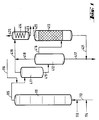
- the reactors (111), (211) and (311) are divided into individual reaction chambers by a plurality of sieve trays.
- the distance between the trays is 1 to 5 times, preferably 1 to 3 times the column diameter.
- the sieve trays are only indicated in the figure.
- the reactor (111) is provided at the bottom with feed lines for olefin (112), chromosulfuric acid (113) and air (114).
- a pipe (115) leads from the head of the reactor (111) into the upper third of the degassing vessel (411).
- a pipeline leads halfway up into the separation vessel (412), the upper part of which is connected by a pipeline (416) to the lower part of the degasser (413).
- An exhaust pipe (419) leads from the head of the degassing vessel (411), and an exhaust pipe (418) leads from the head of the separation vessel (412) to a condensate separator (414).
- a drain (417) leads from the bottom of the separation vessel (412) to a chromic acid treatment plant (not shown).
- a derivative (421) coming from the bottom of the de-chromer (413) opens into this derivative (417).
- the Entchromer (413) is shown here as an adsorption column. He will emptied overhead through line (422).
- the condensate separator (414) is provided with an exhaust pipe (420) at the head and with a discharge pipe (423) at the bottom.
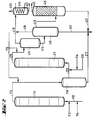
- the apparatus for the two-stage process is identical to the apparatus for the one-stage process, but with the additional apparatus parts of items (211) to (216).
- the reactor (111) is provided at the bottom with feed lines for olefin (112), chromosulfuric acid (113) and air (114).
- a pipe (115) leads from the head of the reactor (111) into the separation vessel (216), from the upper third of which a pipe (212) leads to the bottom of the reactor (211).
- a supply line (214) for air and a supply line (213) for fresh chromic acid are connected to the tube (212) near the bottom of the reactor (211).
- a pipe (215) leads from the top of the reactor (211) into the upper third of the degassing vessel (411). From the bottom of the degassing vessel (411), a pipeline leads halfway up into the separation vessel (412), the upper part of which is connected by a pipeline (416) to the lower part of the degasser (413). An exhaust pipe (419) leads from the head of the degassing vessel (411), and an exhaust pipe (418) leads from the head of the separation vessel (412) to a condensate separator (414). Furthermore, a drain (417) leads from the bottom of the separation vessel (412) to a chromic acid treatment plant (not shown). A derivation (421) coming from the bottom of the de-chromer (413) and a derivation (217) from the bottom of the separation vessel (216) open into this derivation (417).
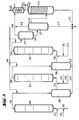
- the apparatus for a three-stage method of operation according to FIG. 3 contains a further group of apparatus parts from positions (311) to (316).
- the reactor (111) is provided at the bottom with feed lines for olefin (112), chromosulfuric acid (113) and air (114).
- a pipe (115) leads from the head of the reactor (111) into the separation vessel (216), from the upper third of which a pipe (212) leads to the bottom of the reactor (211).
- a pipe (215) leads from the head of the reactor (211) into the separation vessel (316), from the upper third of which a pipe (312) leads to the bottom of the reactor (311).
- a supply line (314) for air and a supply line (313) for fresh chromic sulfuric acid are connected to the tube (312) near the bottom of the reactor (311).
- a pipe (315) leads from the top of the reactor (311) into the upper third of the degassing vessel (411).
- the bottom of the separation vessel (316) is connected to the drain (217) by a drain (317).
- a pipeline leads halfway up into the separation vessel (412), the upper part of which is connected by a pipeline (416) to the lower part of the degasser (413).
- An exhaust pipe (419) leads from the head of the degassing vessel (411), and an exhaust pipe (418) leads from the head of the separation vessel (412) to a condensate separator (414).
- a drain (417) leads from the bottom of the separation vessel (412) to a chromic acid treatment plant (not shown).
- a derivation (421) coming from the bottom of the de-chromer (413) and a derivation (217) from the bottom of the separation vessel (216) open into this derivation (417).
- One, two or three stages can optionally be used to carry out the method according to the invention.
- the different reactor stages can be combined with one another.
- one or more reactors can be used for each stage.
- the olefin is introduced into the first reactor (111) via the feed line (112) together with part of the chromosulfuric acid (feed line (113)) and air (feed line (114)).
- the mixture flows through the reactor (111) with intensive mixing.
- the product is then passed into a degassing stage consisting of the degassing vessel (411) and the separation vessel (412).
- the volatile constituents are removed overhead and the condensable components are removed from the exhaust gas stream in a condensate separator (414).
- the exhaust gas is discharged via the discharge line (420) and the condensate via the discharge line (423).
- the oxidate is freed from colloidally distributed or chemically bound chromium compounds in the de-chromer (413).
- This cleaning can take the form of a washing stage, an adsorption stage or a separation using a centrifuge.
- the oxidate is withdrawn via line (422).
- the spent chromic sulfuric acid is led to the regeneration via lines (417) and (421).
- reaction mixture from reactor (111) is placed in a separation vessel (216). There the oxidate separates from the chromosulfuric acid, which flows through line (217) for regeneration, and is metered into the reactor (211) with fresh chromosulfuric acid and air via line (212). From this reactor, the reaction mixture continues to flow into the treatment stages described above.
- the three-stage mode of operation according to FIG. 3 proceeds in the same way, with a reactor (311) and a separation vessel (316) being connected between the reactor (211) and the degassing vessel (411).
- reaction mixture is thus separated after each stage and either processed into the end product or metered into the next stage together with fresh chromium sulfuric acid and air.
- olefins with an internal double bond having a total of 16 to 70, preferably 20 to 50, carbon atoms are used.
- olefins examples include hexadecen-1, octadecen-1, eicosen-1, docosen-1, tetracosen-1, triaconten-1, 2-ethyl-triaconten-1 and 1-olefin mixtures, which mainly consist of C 22 - to C 50 -Olefins exist.
- a solution of CrO 3 and Cr 2 (SO 4 ) 3 , optionally also of alkali dichromate, in aqueous sulfuric acid serves as the oxidizing agent. Approx. 1 molar solutions are used, based on the CrO 3 content. In general, the chromosulphuric acid used contains 500 to 600 g H 2 SO 4 and 95 to 110 g CrO 3 in dm 3 .
- the amount of chromic sulfuric acid required to oxidize the olefin to the desired degree of conversion can already be fed to the reactor of the first reaction stage together with the olefin melt in the multi-stage process.
- the method of dosing the chromosulfuric acid in portions has proven to be better.
- the oxidizing agent used is separated off in a separating vessel and discharged.
- the quantitative ratio of olefin to oxidizing agent depends on the molar mass of the olefinic component and its reactivity.
- JZ iodine number
- a total amount of 120 to 150% by weight is used. corresponding to 165 to 200 mol% of CrO 3, based on the olefin used, in order to obtain a mixture of long-chain aliphatic carboxylic acids with an acid number (SZ) of 105 to 125.
- a carboxylic acid mixture with SZ 105 is obtained.
- the oxidizing agent is used in the first stage and in the second stage about 60 wt .-% added.
- a three-stage reaction with an oxidizer use of 60% by weight in the first stage, 50% by weight in the second stage and 30% in the third stage leads to a carboxylic acid mixture with an acid number SZ of 120 to 125 with an olefin conversion of> 95% .
- the reaction is carried out at a temperature of about 90 ° C. to 200 ° C., preferably in the range from 110 ° C. to 125 ° C. and at a pressure of 100 mbar to 20 bar, preferably 1 bar to 5 bar.
- the residence times in the individual reactor stages are 60 minutes to 180 minutes. The residence time depends on the phase ratio and the desired olefin or oxidant conversion.
- Carboxylic acid mixtures produced by the process according to the invention can be processed with monoalcohols or polyols such as glycol, glycerol, trimethylolpropane, pentaerythritol or sorbitol to form esters and partial esters or to mixtures of such esters.
- monoalcohols or polyols such as glycol, glycerol, trimethylolpropane, pentaerythritol or sorbitol
- esters and partial esters or to mixtures of such esters By reaction with basic oxides or metal hydroxides, the corresponding soaps of the carboxylic acids can be prepared by direct reaction or by reprecipitation.
- the amides, amide esters and amino esters are obtained by reaction with amines or amino alcohols.
- esters and / or soaps can be used as paste waxes, emulsion waxes, release agents or as lubricants.
- An olefin mixture of vinyl olefin, vinylidene olefin and olefin with internal double bonds with an iodine number (JZ) of 45 (Chevron C 30+ olefin) was melted and placed in a heated storage vessel. The temperature of the melt was adjusted to 95 to 100 ° C by steam heating. The olefin was fed into the first reactor via a steam-heated line and a heated pump.
- the chromic acid was fed from a temperature-controlled storage vessel into the reactor via an acid-proof pump. Air was introduced into the reactor at a pressure of 0.5 bar in an amount of 100 dm 3 / h.
- the three components were mixed at the bottom of the reactor in a multi-component nozzle and injected into the first reactor chamber.
- the reaction mixture was conveyed through the reactor chambers and, after passing through the individual reactor stages, passed into the separation vessel via the degassing.
- the used oxidizing agent was separated off there. At this point, the separation could be improved by adding a separating agent (amount 0.1 to 0.5% by weight, based on the olefin used).
- the olefin was melted and placed in a heated storage vessel. The temperature of the melt was adjusted to 95 to 100 ° C by steam heating. The olefin was fed into the first reactor via a steam-heated line and a heated pump. The chromic acid was made from a temperature-controlled storage vessel conveyed into the reactor via an acid-proof pump. Air was introduced into the reactor at a pressure of 0.5 bar in an amount of 100 dm 3 / h.
- the three components were mixed at the bottom of the reactor in a multi-component nozzle and injected into the first reactor chamber. It was possible to work with an increased delivery rate when filling the reactors. The flow rate of olefin and chromic acid was then reduced to ensure optimal use of oxidants.
- the reaction mixture was conveyed through the reactor chambers and, after passing through the individual reactor stages, passed into the separation vessel via the degassing.
- the used oxidizing agent was separated off there.
- the separation could be improved by adding a separating agent (amount 0.1 to 0.5% by weight, based on the olefin used).
- the olefin was melted and placed in a heated storage vessel. The temperature of the melt was adjusted to 95 to 100 ° C by steam heating. The olefin was fed into the first reactor via a steam-heated line and a heated pump. The chromic acid was fed from a temperature-controlled storage vessel into the reactor via an acid-proof pump. Air was introduced into the reactor at a pressure of 0.5 bar in an amount of 100 dm 3 / h.
- the three components were mixed at the bottom of the reactor in a multi-component nozzle and injected into the first reactor chamber.
- the reaction mixture was conveyed through the reactor chambers and, after passing through the first reaction stage, placed in the separation vessel, the used oxidizing agent was separated off and the pre-oxidized olefin was conveyed together with fresh chromic acid and air into the second reaction stage.
- the product was degassed, the used oxidizing agent was separated off and residual chromium compounds were removed from the oxidate in a centrifuge.
- Table 3 Continuous oxidation of ⁇ -olefin tests with variable olefin / chromic acid metering, 2nd stage attempt Wax 10 cm 3 / h Chrome.
- Example 3 The procedure was as in Example 3. After the second reaction stage, the oxidate was introduced into the third reaction stage with fresh chromic acid and worked up as described above. When using 50% by weight of CrO 3, an SZ 125 oxidate was obtained.
Claims (5)
- Procédé de préparation en continu d'acides carboxyliques aliphatiques linéaires de haut poids moléculaire, par oxydation d'oléfines contenant 16 à 70 atomes de carbone avec un mélange sulfochromique 1 molaire environ par rapport à CrO3, à une température de 90 à 200°C et une pression de 100 mbar à 20 bar, caractérisé en ce que la réaction est réalisée à courants parallèles, dans au moins un réacteur à intervalle étroit de temps de séjour, le mélange intime des réactants se faisant à l'aide de la vapeur d'eau qui se forme suite à la chaleur réactionnelle et du gaz de réaction ainsi que par une insufflation supplémentaire d'air.
- Procédé selon la revendication 1, caractérisé en ce que la réaction est réalisée dans un réacteur à colonnes à bulles en cascade.
- Procédé selon la revendication 1, caractérisé en ce que la réaction est réalisée en plusieurs étapes, le mélange sulfochromique usé étant séparé après chaque étape et la quantité de mélange sulfochromique nécessaire pour l'oxydation étant ajoutée en continu par quantités partielles au début de chaque étape.
- Procédé selon la revendication 1, caractérisé en ce que l'on utilise des oléfines C20 à C50 à doubles liaisons internes ou à doubles liaisons vinylidèniques ou à doubles liaisons vinyliques ou des mélanges de ces composés.
- Procédé selon la revendication 1, caractérisé en ce que la séparation entre phase organique et phase inorganique dans le récipient de séparation est accélérée par l'ajout de composés tensioactifs.
Applications Claiming Priority (2)
| Application Number | Priority Date | Filing Date | Title |
|---|---|---|---|
| DE4324719 | 1993-07-23 | ||
| DE4324719 | 1993-07-23 |
Publications (2)
| Publication Number | Publication Date |
|---|---|
| EP0635475A1 EP0635475A1 (fr) | 1995-01-25 |
| EP0635475B1 true EP0635475B1 (fr) | 1997-05-28 |
Family
ID=6493511
Family Applications (1)
| Application Number | Title | Priority Date | Filing Date |
|---|---|---|---|
| EP94111132A Expired - Lifetime EP0635475B1 (fr) | 1993-07-23 | 1994-07-18 | Procédé pour la préparation continue des acides carboxyliques supérieurs |
Country Status (11)
| Country | Link |
|---|---|
| EP (1) | EP0635475B1 (fr) |
| JP (1) | JPH0753444A (fr) |
| AT (1) | ATE153647T1 (fr) |
| AU (1) | AU673440B2 (fr) |
| BR (1) | BR9402918A (fr) |
| CA (1) | CA2128648A1 (fr) |
| DE (1) | DE59402888D1 (fr) |
| DK (1) | DK0635475T3 (fr) |
| ES (1) | ES2105434T3 (fr) |
| HK (1) | HK1006709A1 (fr) |
| TW (1) | TW277064B (fr) |
Family Cites Families (2)
| Publication number | Priority date | Publication date | Assignee | Title |
|---|---|---|---|---|
| DE2165858C3 (de) * | 1971-12-31 | 1974-11-28 | Farbwerke Hoechst Ag, Vormals Meister Lucius & Bruening, 6000 Frankfurt | Verfahren zur Herstellung von höhermolekularen, aliphatischen Monocarbonsäuren |
| DE2855263C2 (de) * | 1978-12-21 | 1983-11-24 | Hoechst Ag, 6230 Frankfurt | Verfahren zur kontinuierlichen oxidativen Bleichung von Rohmontanwachs |
-
1994
- 1994-06-03 TW TW083105085A patent/TW277064B/zh active
- 1994-07-18 EP EP94111132A patent/EP0635475B1/fr not_active Expired - Lifetime
- 1994-07-18 ES ES94111132T patent/ES2105434T3/es not_active Expired - Lifetime
- 1994-07-18 AT AT94111132T patent/ATE153647T1/de not_active IP Right Cessation
- 1994-07-18 DK DK94111132.0T patent/DK0635475T3/da active
- 1994-07-18 DE DE59402888T patent/DE59402888D1/de not_active Expired - Fee Related
- 1994-07-21 AU AU68603/94A patent/AU673440B2/en not_active Ceased
- 1994-07-22 JP JP6171237A patent/JPH0753444A/ja active Pending
- 1994-07-22 BR BR9402918A patent/BR9402918A/pt not_active Application Discontinuation
- 1994-07-22 CA CA002128648A patent/CA2128648A1/fr not_active Abandoned
-
1998
- 1998-06-23 HK HK98106078A patent/HK1006709A1/xx not_active IP Right Cessation
Also Published As
| Publication number | Publication date |
|---|---|
| CA2128648A1 (fr) | 1995-01-24 |
| AU6860394A (en) | 1995-02-02 |
| HK1006709A1 (en) | 1999-03-12 |
| ATE153647T1 (de) | 1997-06-15 |
| DK0635475T3 (da) | 1997-12-15 |
| AU673440B2 (en) | 1996-11-07 |
| DE59402888D1 (de) | 1997-07-03 |
| BR9402918A (pt) | 1995-04-11 |
| JPH0753444A (ja) | 1995-02-28 |
| TW277064B (fr) | 1996-06-01 |
| EP0635475A1 (fr) | 1995-01-25 |
| ES2105434T3 (es) | 1997-10-16 |
Similar Documents
| Publication | Publication Date | Title |
|---|---|---|
| EP1015410B1 (fr) | Procede pour la preparation d'acide acrylique et d'acide methacrylique | |
| DE2515419C2 (fr) | ||
| DE4308087A1 (de) | Verfahren zur Abtrennung von Acrylsäure aus den Reaktionsgasen der katalytischen Oxidation von Propylen und/oder Acrolein | |
| DE2834140C2 (fr) | ||
| DE60005870T2 (de) | Verfahren zur Herstellung von Acrylsäure | |
| EP1066239A1 (fr) | Procede de preparation d'acide acrylique et d'esters d'acide acrylique | |
| WO1998040342A1 (fr) | Procede d'extraction d'acide (meth)acrylique | |
| DE10031518A1 (de) | Verfahren zur Herstellung von Hydroformylierungsprodukten des Propylens und von Acrylsäure und/oder Acrolein | |
| DE19709471A1 (de) | Verfahren zur Herstellung von (Meth)acrylsäure | |
| EP0962444B1 (fr) | Procédé de traitement d'acétate de vinyle brut liquide | |
| EP0963373A1 (fr) | Procede de distillation d'oxyde d'ethylene pur | |
| EP0635475B1 (fr) | Procédé pour la préparation continue des acides carboxyliques supérieurs | |
| DE1543173C3 (de) | Verfahren zur Herstellung und Gewinnung von Propenoxid, Essigsäure und anderen wertvollen Oxidationsprodukten | |
| DE2737894C2 (fr) | ||
| DD151115A5 (de) | Verfahren zur gewinnung und wiederverwendung von oxydationskatalysator | |
| DE1668480A1 (de) | Verfahren zur Herstellung von AEthylbenzolhydroperoxyd | |
| EP0835861B1 (fr) | Oxydation dans le procédé Witten-Hercules pour la préparation du téréphtalate de diméthyle | |
| EP1317491B1 (fr) | Procede pour l'hydroformylation continue de polyalcenes ayant 30 a 700 atomes de carbone | |
| EP1204472A1 (fr) | Procede de production d'esters a partir d'acides carboxyliques non satures et d'alcools polyvalents | |
| DE2632898A1 (de) | Kobaltkatalysierte oxidation von gesaettigten, aliphatischen c tief 3 - c tief 7 -kohlenwasserstoffen zu essigsaeure | |
| DE19836367A1 (de) | Isolierung von Carbonsäuren durch Aminkomplexe | |
| CH656608A5 (de) | Verfahren zur herstellung von acylium-anion-produkten, acrylsaeure und methacrylsaeure. | |
| EP1932821A1 (fr) | Procédé de fabrication de produits d'oxydation du cyclohexane | |
| DD157700A5 (de) | Verfahren zur gewinnung von c tief 2-bis c tief 4-alkoholen | |
| DE2838880B2 (de) | Verfahren zur Gewinnung von Methacrolein |
Legal Events
| Date | Code | Title | Description |
|---|---|---|---|
| PUAI | Public reference made under article 153(3) epc to a published international application that has entered the european phase |
Free format text: ORIGINAL CODE: 0009012 |
|
| AK | Designated contracting states |
Kind code of ref document: A1 Designated state(s): AT BE CH DE DK ES FR GB IE IT LI NL PT SE |
|
| 17P | Request for examination filed |
Effective date: 19950725 |
|
| GRAG | Despatch of communication of intention to grant |
Free format text: ORIGINAL CODE: EPIDOS AGRA |
|
| 17Q | First examination report despatched |
Effective date: 19960902 |
|
| GRAH | Despatch of communication of intention to grant a patent |
Free format text: ORIGINAL CODE: EPIDOS IGRA |
|
| GRAH | Despatch of communication of intention to grant a patent |
Free format text: ORIGINAL CODE: EPIDOS IGRA |
|
| GRAA | (expected) grant |
Free format text: ORIGINAL CODE: 0009210 |
|
| AK | Designated contracting states |
Kind code of ref document: B1 Designated state(s): AT BE CH DE DK ES FR GB IE IT LI NL PT SE |
|
| REF | Corresponds to: |
Ref document number: 153647 Country of ref document: AT Date of ref document: 19970615 Kind code of ref document: T |
|
| REG | Reference to a national code |
Ref country code: CH Ref legal event code: EP |
|
| REF | Corresponds to: |
Ref document number: 59402888 Country of ref document: DE Date of ref document: 19970703 |
|
| GBT | Gb: translation of ep patent filed (gb section 77(6)(a)/1977) |
Effective date: 19970731 |
|
| ET | Fr: translation filed | ||
| REG | Reference to a national code |
Ref country code: ES Ref legal event code: FG2A Ref document number: 2105434 Country of ref document: ES Kind code of ref document: T3 |
|
| REG | Reference to a national code |
Ref country code: PT Ref legal event code: SC4A Free format text: AVAILABILITY OF NATIONAL TRANSLATION Effective date: 19970731 |
|
| REG | Reference to a national code |
Ref country code: DK Ref legal event code: T3 |
|
| PLBE | No opposition filed within time limit |
Free format text: ORIGINAL CODE: 0009261 |
|
| STAA | Information on the status of an ep patent application or granted ep patent |
Free format text: STATUS: NO OPPOSITION FILED WITHIN TIME LIMIT |
|
| 26N | No opposition filed | ||
| PGFP | Annual fee paid to national office [announced via postgrant information from national office to epo] |
Ref country code: DK Payment date: 19980525 Year of fee payment: 5 |
|
| PGFP | Annual fee paid to national office [announced via postgrant information from national office to epo] |
Ref country code: PT Payment date: 19980602 Year of fee payment: 5 |
|
| PGFP | Annual fee paid to national office [announced via postgrant information from national office to epo] |
Ref country code: IE Payment date: 19980605 Year of fee payment: 5 |
|
| PGFP | Annual fee paid to national office [announced via postgrant information from national office to epo] |
Ref country code: NL Payment date: 19990615 Year of fee payment: 6 |
|
| PGFP | Annual fee paid to national office [announced via postgrant information from national office to epo] |
Ref country code: FR Payment date: 19990616 Year of fee payment: 6 Ref country code: AT Payment date: 19990616 Year of fee payment: 6 |
|
| PGFP | Annual fee paid to national office [announced via postgrant information from national office to epo] |
Ref country code: DE Payment date: 19990617 Year of fee payment: 6 |
|
| PGFP | Annual fee paid to national office [announced via postgrant information from national office to epo] |
Ref country code: SE Payment date: 19990618 Year of fee payment: 6 Ref country code: GB Payment date: 19990618 Year of fee payment: 6 |
|
| PGFP | Annual fee paid to national office [announced via postgrant information from national office to epo] |
Ref country code: CH Payment date: 19990621 Year of fee payment: 6 |
|
| PG25 | Lapsed in a contracting state [announced via postgrant information from national office to epo] |
Ref country code: IE Free format text: LAPSE BECAUSE OF NON-PAYMENT OF DUE FEES Effective date: 19990718 |
|
| PGFP | Annual fee paid to national office [announced via postgrant information from national office to epo] |
Ref country code: BE Payment date: 19990720 Year of fee payment: 6 |
|
| PGFP | Annual fee paid to national office [announced via postgrant information from national office to epo] |
Ref country code: ES Payment date: 19990729 Year of fee payment: 6 |
|
| PG25 | Lapsed in a contracting state [announced via postgrant information from national office to epo] |
Ref country code: DK Free format text: LAPSE BECAUSE OF NON-PAYMENT OF DUE FEES Effective date: 19990802 |
|
| REG | Reference to a national code |
Ref country code: CH Ref legal event code: PUE Owner name: HOECHST AKTIENGESELLSCHAFT TRANSFER- CLARIANT GMBH |
|
| BECA | Be: change of holder's address |
Free format text: 19991028 *CLARIANT G.M.B.H.:BRUENINGSTRASSE 50, 65929 FRANKFURT AM MAIN |
|
| PG25 | Lapsed in a contracting state [announced via postgrant information from national office to epo] |
Ref country code: PT Free format text: LAPSE BECAUSE OF NON-PAYMENT OF DUE FEES Effective date: 20000131 |
|
| REG | Reference to a national code |
Ref country code: FR Ref legal event code: TP |
|
| REG | Reference to a national code |
Ref country code: DK Ref legal event code: EBP |
|
| NLS | Nl: assignments of ep-patents |
Owner name: CLARIANT GMBH |
|
| REG | Reference to a national code |
Ref country code: IE Ref legal event code: MM4A |
|
| REG | Reference to a national code |
Ref country code: PT Ref legal event code: MM4A Free format text: LAPSE DUE TO NON-PAYMENT OF FEES Effective date: 20000131 |
|
| PG25 | Lapsed in a contracting state [announced via postgrant information from national office to epo] |
Ref country code: GB Free format text: LAPSE BECAUSE OF NON-PAYMENT OF DUE FEES Effective date: 20000718 Ref country code: AT Free format text: LAPSE BECAUSE OF NON-PAYMENT OF DUE FEES Effective date: 20000718 |
|
| PG25 | Lapsed in a contracting state [announced via postgrant information from national office to epo] |
Ref country code: SE Free format text: LAPSE BECAUSE OF NON-PAYMENT OF DUE FEES Effective date: 20000719 Ref country code: ES Free format text: LAPSE BECAUSE OF NON-PAYMENT OF DUE FEES Effective date: 20000719 |
|
| PG25 | Lapsed in a contracting state [announced via postgrant information from national office to epo] |
Ref country code: LI Free format text: LAPSE BECAUSE OF NON-PAYMENT OF DUE FEES Effective date: 20000731 Ref country code: CH Free format text: LAPSE BECAUSE OF NON-PAYMENT OF DUE FEES Effective date: 20000731 Ref country code: BE Free format text: LAPSE BECAUSE OF NON-PAYMENT OF DUE FEES Effective date: 20000731 |
|
| REG | Reference to a national code |
Ref country code: GB Ref legal event code: 732E |
|
| BERE | Be: lapsed |
Owner name: CLARIANT G.M.B.H. Effective date: 20000731 |
|
| PG25 | Lapsed in a contracting state [announced via postgrant information from national office to epo] |
Ref country code: NL Free format text: LAPSE BECAUSE OF NON-PAYMENT OF DUE FEES Effective date: 20010201 |
|
| GBPC | Gb: european patent ceased through non-payment of renewal fee |
Effective date: 20000718 |
|
| REG | Reference to a national code |
Ref country code: CH Ref legal event code: PL |
|
| EUG | Se: european patent has lapsed |
Ref document number: 94111132.0 |
|
| PG25 | Lapsed in a contracting state [announced via postgrant information from national office to epo] |
Ref country code: FR Free format text: LAPSE BECAUSE OF NON-PAYMENT OF DUE FEES Effective date: 20010330 |
|
| NLV4 | Nl: lapsed or anulled due to non-payment of the annual fee |
Effective date: 20010201 |
|
| REG | Reference to a national code |
Ref country code: FR Ref legal event code: ST |
|
| PG25 | Lapsed in a contracting state [announced via postgrant information from national office to epo] |
Ref country code: DE Free format text: LAPSE BECAUSE OF NON-PAYMENT OF DUE FEES Effective date: 20010501 |
|
| REG | Reference to a national code |
Ref country code: ES Ref legal event code: FD2A Effective date: 20010810 |
|
| PG25 | Lapsed in a contracting state [announced via postgrant information from national office to epo] |
Ref country code: IT Free format text: LAPSE BECAUSE OF NON-PAYMENT OF DUE FEES;WARNING: LAPSES OF ITALIAN PATENTS WITH EFFECTIVE DATE BEFORE 2007 MAY HAVE OCCURRED AT ANY TIME BEFORE 2007. THE CORRECT EFFECTIVE DATE MAY BE DIFFERENT FROM THE ONE RECORDED. Effective date: 20050718 |