EP0635475B1 - Process for the continuous production of higher molecular carboxylic acids - Google Patents
Process for the continuous production of higher molecular carboxylic acids Download PDFInfo
- Publication number
- EP0635475B1 EP0635475B1 EP94111132A EP94111132A EP0635475B1 EP 0635475 B1 EP0635475 B1 EP 0635475B1 EP 94111132 A EP94111132 A EP 94111132A EP 94111132 A EP94111132 A EP 94111132A EP 0635475 B1 EP0635475 B1 EP 0635475B1
- Authority
- EP
- European Patent Office
- Prior art keywords
- reaction
- reactor
- olefin
- stage
- chromic
- Prior art date
- Legal status (The legal status is an assumption and is not a legal conclusion. Google has not performed a legal analysis and makes no representation as to the accuracy of the status listed.)
- Expired - Lifetime
Links
Images
Classifications
-
- C—CHEMISTRY; METALLURGY
- C07—ORGANIC CHEMISTRY
- C07C—ACYCLIC OR CARBOCYCLIC COMPOUNDS
- C07C51/00—Preparation of carboxylic acids or their salts, halides or anhydrides
- C07C51/16—Preparation of carboxylic acids or their salts, halides or anhydrides by oxidation
- C07C51/305—Preparation of carboxylic acids or their salts, halides or anhydrides by oxidation with sulfur or sulfur-containing compounds
Definitions
- the invention relates to a process for the production of higher molecular weight carboxylic acids by oxidation of ethylenically unsaturated compounds with chromic acid.
- the invention thus relates to a process for the continuous production of higher molecular weight, linear aliphatic carboxylic acids by oxidation of olefins having 16 to 70 carbon atoms with about 1 molar, based on CrO 3 , chromic sulfuric acid at a temperature of 90 to 200 ° C and one Pressure from 100 mbar to 20 bar, characterized in that the reaction is carried out in cocurrent in at least one reactor with a narrow residence time spectrum, the mixing of the reactants being carried out by the water vapor resulting from the heat of reaction and the reaction gas and additional blowing in of air.
- the process according to the invention is carried out in continuously operated reactors with the characteristic of a narrow residence time spectrum, such as, for example, in tubular reactors, stirred tank cascades or cascaded bubble column reactors with sieve trays, the cascaded bubble column reactors being preferably used.
- These reactors are characterized in particular by the fact that the reactants are mixed very effectively by the water vapor resulting from the exothermic reaction, by the release of gaseous reaction products, by the blowing in of air / water vapor and by the arrangement and shape of the sieve trays, without this requires the installation of moving mechanical parts.
- Another advantage of the bubble column cascade reactors is that the resulting water vapor removes low molecular weight and water vapor volatile oxidation products from the reactor. Without this stripping process, these products would either be in the spent chromic sulfuric acid remain and interfere with their regeneration, or they remain in the oxidate and interfere with the further use of this oxidate.
- the reactors (111), (211) and (311) are divided into individual reaction chambers by a plurality of sieve trays.
- the distance between the trays is 1 to 5 times, preferably 1 to 3 times the column diameter.
- the sieve trays are only indicated in the figure.
- the reactor (111) is provided at the bottom with feed lines for olefin (112), chromosulfuric acid (113) and air (114).
- a pipe (115) leads from the head of the reactor (111) into the upper third of the degassing vessel (411).
- a pipeline leads halfway up into the separation vessel (412), the upper part of which is connected by a pipeline (416) to the lower part of the degasser (413).
- An exhaust pipe (419) leads from the head of the degassing vessel (411), and an exhaust pipe (418) leads from the head of the separation vessel (412) to a condensate separator (414).
- a drain (417) leads from the bottom of the separation vessel (412) to a chromic acid treatment plant (not shown).
- a derivative (421) coming from the bottom of the de-chromer (413) opens into this derivative (417).
- the Entchromer (413) is shown here as an adsorption column. He will emptied overhead through line (422).
- the condensate separator (414) is provided with an exhaust pipe (420) at the head and with a discharge pipe (423) at the bottom.
- the apparatus for the two-stage process is identical to the apparatus for the one-stage process, but with the additional apparatus parts of items (211) to (216).
- the reactor (111) is provided at the bottom with feed lines for olefin (112), chromosulfuric acid (113) and air (114).
- a pipe (115) leads from the head of the reactor (111) into the separation vessel (216), from the upper third of which a pipe (212) leads to the bottom of the reactor (211).
- a supply line (214) for air and a supply line (213) for fresh chromic acid are connected to the tube (212) near the bottom of the reactor (211).
- a pipe (215) leads from the top of the reactor (211) into the upper third of the degassing vessel (411). From the bottom of the degassing vessel (411), a pipeline leads halfway up into the separation vessel (412), the upper part of which is connected by a pipeline (416) to the lower part of the degasser (413). An exhaust pipe (419) leads from the head of the degassing vessel (411), and an exhaust pipe (418) leads from the head of the separation vessel (412) to a condensate separator (414). Furthermore, a drain (417) leads from the bottom of the separation vessel (412) to a chromic acid treatment plant (not shown). A derivation (421) coming from the bottom of the de-chromer (413) and a derivation (217) from the bottom of the separation vessel (216) open into this derivation (417).
- the apparatus for a three-stage method of operation according to FIG. 3 contains a further group of apparatus parts from positions (311) to (316).
- the reactor (111) is provided at the bottom with feed lines for olefin (112), chromosulfuric acid (113) and air (114).
- a pipe (115) leads from the head of the reactor (111) into the separation vessel (216), from the upper third of which a pipe (212) leads to the bottom of the reactor (211).
- a pipe (215) leads from the head of the reactor (211) into the separation vessel (316), from the upper third of which a pipe (312) leads to the bottom of the reactor (311).
- a supply line (314) for air and a supply line (313) for fresh chromic sulfuric acid are connected to the tube (312) near the bottom of the reactor (311).
- a pipe (315) leads from the top of the reactor (311) into the upper third of the degassing vessel (411).
- the bottom of the separation vessel (316) is connected to the drain (217) by a drain (317).
- a pipeline leads halfway up into the separation vessel (412), the upper part of which is connected by a pipeline (416) to the lower part of the degasser (413).
- An exhaust pipe (419) leads from the head of the degassing vessel (411), and an exhaust pipe (418) leads from the head of the separation vessel (412) to a condensate separator (414).
- a drain (417) leads from the bottom of the separation vessel (412) to a chromic acid treatment plant (not shown).
- a derivation (421) coming from the bottom of the de-chromer (413) and a derivation (217) from the bottom of the separation vessel (216) open into this derivation (417).
- One, two or three stages can optionally be used to carry out the method according to the invention.
- the different reactor stages can be combined with one another.
- one or more reactors can be used for each stage.
- the olefin is introduced into the first reactor (111) via the feed line (112) together with part of the chromosulfuric acid (feed line (113)) and air (feed line (114)).
- the mixture flows through the reactor (111) with intensive mixing.
- the product is then passed into a degassing stage consisting of the degassing vessel (411) and the separation vessel (412).
- the volatile constituents are removed overhead and the condensable components are removed from the exhaust gas stream in a condensate separator (414).
- the exhaust gas is discharged via the discharge line (420) and the condensate via the discharge line (423).
- the oxidate is freed from colloidally distributed or chemically bound chromium compounds in the de-chromer (413).
- This cleaning can take the form of a washing stage, an adsorption stage or a separation using a centrifuge.
- the oxidate is withdrawn via line (422).
- the spent chromic sulfuric acid is led to the regeneration via lines (417) and (421).
- reaction mixture from reactor (111) is placed in a separation vessel (216). There the oxidate separates from the chromosulfuric acid, which flows through line (217) for regeneration, and is metered into the reactor (211) with fresh chromosulfuric acid and air via line (212). From this reactor, the reaction mixture continues to flow into the treatment stages described above.
- the three-stage mode of operation according to FIG. 3 proceeds in the same way, with a reactor (311) and a separation vessel (316) being connected between the reactor (211) and the degassing vessel (411).
- reaction mixture is thus separated after each stage and either processed into the end product or metered into the next stage together with fresh chromium sulfuric acid and air.
- olefins with an internal double bond having a total of 16 to 70, preferably 20 to 50, carbon atoms are used.
- olefins examples include hexadecen-1, octadecen-1, eicosen-1, docosen-1, tetracosen-1, triaconten-1, 2-ethyl-triaconten-1 and 1-olefin mixtures, which mainly consist of C 22 - to C 50 -Olefins exist.
- a solution of CrO 3 and Cr 2 (SO 4 ) 3 , optionally also of alkali dichromate, in aqueous sulfuric acid serves as the oxidizing agent. Approx. 1 molar solutions are used, based on the CrO 3 content. In general, the chromosulphuric acid used contains 500 to 600 g H 2 SO 4 and 95 to 110 g CrO 3 in dm 3 .
- the amount of chromic sulfuric acid required to oxidize the olefin to the desired degree of conversion can already be fed to the reactor of the first reaction stage together with the olefin melt in the multi-stage process.
- the method of dosing the chromosulfuric acid in portions has proven to be better.
- the oxidizing agent used is separated off in a separating vessel and discharged.
- the quantitative ratio of olefin to oxidizing agent depends on the molar mass of the olefinic component and its reactivity.
- JZ iodine number
- a total amount of 120 to 150% by weight is used. corresponding to 165 to 200 mol% of CrO 3, based on the olefin used, in order to obtain a mixture of long-chain aliphatic carboxylic acids with an acid number (SZ) of 105 to 125.
- a carboxylic acid mixture with SZ 105 is obtained.
- the oxidizing agent is used in the first stage and in the second stage about 60 wt .-% added.
- a three-stage reaction with an oxidizer use of 60% by weight in the first stage, 50% by weight in the second stage and 30% in the third stage leads to a carboxylic acid mixture with an acid number SZ of 120 to 125 with an olefin conversion of> 95% .
- the reaction is carried out at a temperature of about 90 ° C. to 200 ° C., preferably in the range from 110 ° C. to 125 ° C. and at a pressure of 100 mbar to 20 bar, preferably 1 bar to 5 bar.
- the residence times in the individual reactor stages are 60 minutes to 180 minutes. The residence time depends on the phase ratio and the desired olefin or oxidant conversion.
- Carboxylic acid mixtures produced by the process according to the invention can be processed with monoalcohols or polyols such as glycol, glycerol, trimethylolpropane, pentaerythritol or sorbitol to form esters and partial esters or to mixtures of such esters.
- monoalcohols or polyols such as glycol, glycerol, trimethylolpropane, pentaerythritol or sorbitol
- esters and partial esters or to mixtures of such esters By reaction with basic oxides or metal hydroxides, the corresponding soaps of the carboxylic acids can be prepared by direct reaction or by reprecipitation.
- the amides, amide esters and amino esters are obtained by reaction with amines or amino alcohols.
- esters and / or soaps can be used as paste waxes, emulsion waxes, release agents or as lubricants.
- An olefin mixture of vinyl olefin, vinylidene olefin and olefin with internal double bonds with an iodine number (JZ) of 45 (Chevron C 30+ olefin) was melted and placed in a heated storage vessel. The temperature of the melt was adjusted to 95 to 100 ° C by steam heating. The olefin was fed into the first reactor via a steam-heated line and a heated pump.
- the chromic acid was fed from a temperature-controlled storage vessel into the reactor via an acid-proof pump. Air was introduced into the reactor at a pressure of 0.5 bar in an amount of 100 dm 3 / h.
- the three components were mixed at the bottom of the reactor in a multi-component nozzle and injected into the first reactor chamber.
- the reaction mixture was conveyed through the reactor chambers and, after passing through the individual reactor stages, passed into the separation vessel via the degassing.
- the used oxidizing agent was separated off there. At this point, the separation could be improved by adding a separating agent (amount 0.1 to 0.5% by weight, based on the olefin used).
- the olefin was melted and placed in a heated storage vessel. The temperature of the melt was adjusted to 95 to 100 ° C by steam heating. The olefin was fed into the first reactor via a steam-heated line and a heated pump. The chromic acid was made from a temperature-controlled storage vessel conveyed into the reactor via an acid-proof pump. Air was introduced into the reactor at a pressure of 0.5 bar in an amount of 100 dm 3 / h.
- the three components were mixed at the bottom of the reactor in a multi-component nozzle and injected into the first reactor chamber. It was possible to work with an increased delivery rate when filling the reactors. The flow rate of olefin and chromic acid was then reduced to ensure optimal use of oxidants.
- the reaction mixture was conveyed through the reactor chambers and, after passing through the individual reactor stages, passed into the separation vessel via the degassing.
- the used oxidizing agent was separated off there.
- the separation could be improved by adding a separating agent (amount 0.1 to 0.5% by weight, based on the olefin used).
- the olefin was melted and placed in a heated storage vessel. The temperature of the melt was adjusted to 95 to 100 ° C by steam heating. The olefin was fed into the first reactor via a steam-heated line and a heated pump. The chromic acid was fed from a temperature-controlled storage vessel into the reactor via an acid-proof pump. Air was introduced into the reactor at a pressure of 0.5 bar in an amount of 100 dm 3 / h.
- the three components were mixed at the bottom of the reactor in a multi-component nozzle and injected into the first reactor chamber.
- the reaction mixture was conveyed through the reactor chambers and, after passing through the first reaction stage, placed in the separation vessel, the used oxidizing agent was separated off and the pre-oxidized olefin was conveyed together with fresh chromic acid and air into the second reaction stage.
- the product was degassed, the used oxidizing agent was separated off and residual chromium compounds were removed from the oxidate in a centrifuge.
- Table 3 Continuous oxidation of ⁇ -olefin tests with variable olefin / chromic acid metering, 2nd stage attempt Wax 10 cm 3 / h Chrome.
- Example 3 The procedure was as in Example 3. After the second reaction stage, the oxidate was introduced into the third reaction stage with fresh chromic acid and worked up as described above. When using 50% by weight of CrO 3, an SZ 125 oxidate was obtained.
Abstract
Description
Die Erfindung bezieht sich auf ein Verfahren zur Herstellung höhermolekularer Carbonsäuren durch Oxidation von ethylenisch ungesättigten Verbindungen mit Chromsäure.The invention relates to a process for the production of higher molecular weight carboxylic acids by oxidation of ethylenically unsaturated compounds with chromic acid.
Zur Herstellung von höhermolekularen, linearen aliphatischen Carbonsäuren sind zahlreiche Synthesen bekannt. Technisch genutzt werden aber nur wenige Verfahren.
So wird der Bedarf an höhermolekularen Fett- oder Wachssäuren fast ausschließlich aus Naturprodukten gedeckt.Numerous syntheses are known for the production of higher molecular weight, linear aliphatic carboxylic acids. However, only a few processes are used technically.
The need for higher molecular fatty or wax acids is almost exclusively covered by natural products.
Technisch realisiert ist die Oxidation von Paraffinen zu Carbonsäuren. Nachteilig bei diesen Verfahren ist aber, daß der Angriff des Oxidationsmittels nicht gesteuert werden kann und eine breite Palette an Carbonsäuren und anderen sauerstoffhaltigen Verbindungen entsteht.The oxidation of paraffins to carboxylic acids is technically realized. However, a disadvantage of these processes is that the attack by the oxidizing agent cannot be controlled and a wide range of carboxylic acids and other oxygen-containing compounds are formed.
Diese Nachteile können vermieden werden, wenn als Rohstoffe längerkettige Olefine und als Oxidationsmittel beispielsweise schwefelsaure Chromsäure eingesetzt werden. Bekannt sind ein- oder mehrstufige Verfahren zur Oxidation von Olefinen (vgl. DE 2 165 858, DE 2 262 130, DE 23 10 425). Diese Verfahren haben neben der unvollständigen Umsetzung, dem hohen Oxidationsmittelverbrauch und der schlechten Abtrennung noch einen weiteren Nachteil, daß die Dispergierung des Olefins im Oxidationsmittel nur ungenügend erfolgt. Außerdem kommt es zur Bildung einer viskosen, chromhaltigen organischen Phase, die einen geregelten Ablauf der Reaktion stört.These disadvantages can be avoided if longer-chain olefins are used as raw materials and, for example, sulfuric acid chromic acid is used as the oxidizing agent. Single- or multi-stage processes for the oxidation of olefins are known (cf. DE 2 165 858, DE 2 262 130, DE 23 10 425). In addition to the incomplete conversion, the high consumption of oxidizing agents and the poor separation, these processes have a further disadvantage that the olefin is not dispersed sufficiently in the oxidizing agent. In addition, a viscous, chromium-containing organic phase is formed, which interferes with the regulated course of the reaction.
Es ist bekannt, daß die Nachteile einer diskontinuierlichen Arbeitsweise bei kontinuierlicher Arbeitsweise ausgeglichen werden können. So wird beispielsweise die oxidative Bleichung von Naturwachsen zur besseren Handhabung der zähen Reaktionsmischung unter Ausnutzung gasförmiger Oxidationsprodukte in einem Reaktor mit der Charakteristik eines engen Verweilzeitspektrums durchgeführt (vgl. DE 28 55 263).It is known that the disadvantages of a discontinuous mode of operation can be compensated for by a continuous mode of operation. So will for example, the oxidative bleaching of natural waxes for better handling of the viscous reaction mixture using gaseous oxidation products in a reactor with the characteristic of a narrow residence time range (cf. DE 28 55 263).
Es wurde gefunden, daß die Oxidation von Olefinen in einer modifizierten Verfahrensweise möglich ist.It has been found that the oxidation of olefins is possible in a modified procedure.
Die Erfindung betrifft somit ein Verfahren zur kontinuierlichen Herstellung von höhermolekularen, linearen aliphatischen Carbonsäuren durch Oxidation von Olefinen mit 16 bis 70 C-Atomen mit ca. 1-molarer, bezogen auf CrO3, Chromschwefelsäure bei einer Temperatur von 90 bis 200°C und einem Druck von 100 mbar bis 20 bar, dadurch gekennzeichnet, daß die Reaktion im Gleichstrom in mindestens einem Reaktor mit engem Verweilzeitspektrum durchgeführt wird, wobei die Durchmischung der Reaktanden durch den infolge der Reaktionswärme entstehenden Wasserdampf und das Reaktionsgas sowie zusätzliches Einblasen von Luft erfolgt.The invention thus relates to a process for the continuous production of higher molecular weight, linear aliphatic carboxylic acids by oxidation of olefins having 16 to 70 carbon atoms with about 1 molar, based on CrO 3 , chromic sulfuric acid at a temperature of 90 to 200 ° C and one Pressure from 100 mbar to 20 bar, characterized in that the reaction is carried out in cocurrent in at least one reactor with a narrow residence time spectrum, the mixing of the reactants being carried out by the water vapor resulting from the heat of reaction and the reaction gas and additional blowing in of air.
Das erfindungsgemäße Verfahren wird in kontinuierlich betriebenen Reaktoren mit der Charakteristik eines engen Verweilzeitspektrums durchgeführt, wie beispielsweise in Rohrreaktoren, Rührkesselkaskaden oder kaskadierten Blasensäulenreaktoren mit Siebböden, wobei die kaskadierten Blasensäulenreaktoren bevorzugt verwendet werden. Diese Reaktoren zeichnen sich vor allem dadurch aus, daß die Durchmischung der Reaktanten durch den infolge der exothermen Reaktion entstehenden Wasserdampf, durch die Freisetzung gasförmiger Reaktionsprodukte, durch das Einblasen von Luft/Wasserdampf und durch die Anordnung und Form der Siebböden sehr effektiv erfolgt, ohne daß dafür der Einbau bewegter mechanischer Teile notwendig ist. Ein weiterer Vorteil der Blasensäulen-Kaskadenreaktoren liegt darin, daß durch den entstehenden Wasserdampf niedermolekulare und wasserdampfflüchtige Oxidationsprodukte aus dem Reaktor ausgetragen werden. Ohne diesen Strippvorgang würden diese Produkte entweder in der verbrauchten Chromschwefelsäure verbleiben und deren Regenerierung stören, oder sie verbleiben im Oxidat und stören bei der weiteren Verwendung dieses Oxidats.The process according to the invention is carried out in continuously operated reactors with the characteristic of a narrow residence time spectrum, such as, for example, in tubular reactors, stirred tank cascades or cascaded bubble column reactors with sieve trays, the cascaded bubble column reactors being preferably used. These reactors are characterized in particular by the fact that the reactants are mixed very effectively by the water vapor resulting from the exothermic reaction, by the release of gaseous reaction products, by the blowing in of air / water vapor and by the arrangement and shape of the sieve trays, without this requires the installation of moving mechanical parts. Another advantage of the bubble column cascade reactors is that the resulting water vapor removes low molecular weight and water vapor volatile oxidation products from the reactor. Without this stripping process, these products would either be in the spent chromic sulfuric acid remain and interfere with their regeneration, or they remain in the oxidate and interfere with the further use of this oxidate.
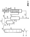
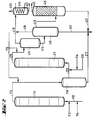
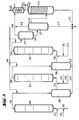
Die für das erfindungsgemäße Verfahren verwendete Apparatur zeigen die Figuren, wobei in Figur 1 eine Apparatur für eine einstufige Arbeitsweise, in Figur 2 eine Apparatur für eine zweistufige Arbeitsweise und in Figur 3 eine Apparatur für eine dreistufige Arbeitsweise dargestellt ist. Es bedeuten in den Figuren
- 111 =
- Reaktor für die 1. Stufe
- 112 =
- Zuleitung für Olefin
- 113 =
- Zuleitung für Chromschwefelsäure
- 114 =
- Zuleitung für Luft
- 115 =
- Rohrleitung
- 116 =
- Zuleitung für Trennmittel
- 211 =
- Reaktor für die 2. Stufe
- 212 =
- Zuleitung für Olefin/Carbonsäuregemisch
- 213 =
- Zuleitung für frische Chromschwefelsäure
- 214 =
- Zuleitung für Luft
- 215 =
- Rohrleitung
- 216 =
- Trenngefäß
- 217 =
- Ableitung
- 311 =
- Reaktor für die 3. Stufe
- 312 =
- Zuleitung für Olefin/Carbonsäuregemisch
- 313 =
- Zuleitung für frische Chromschwefelsäure
- 314 =
- Zuleitung für Luft
- 315 =
- Rohrleitung
- 316 =
- Trenngefäß
- 317 =
- Ableitung
- 411 =
- Entgasungsbehälter
- 412 =
- Trenngefäß für Endprodukt
- 413 =
- Entchromer
- 414 =
- Kondensatabscheider
- 415 =
- Rohrleitung
- 416 =
- Rohrleitung
- 417 =
- Ableitung
- 418 =
- Abgasleitung
- 419 =
- Abgasleitung
- 420 =
- Abgasleitung
- 421 =
- Ableitung
- 422 =
- Austragsleitung für Endprodukt
- 423 =
- Kondensatableitung
- 111 =
- 1st stage reactor
- 112 =
- Supply line for olefin
- 113 =
- Inlet for chrome sulfuric acid
- 114 =
- Air supply line
- 115 =
- Pipeline
- 116 =
- Supply line for release agents
- 211 =
- 2nd stage reactor
- 212 =
- Supply line for olefin / carboxylic acid mixture
- 213 =
- Supply line for fresh chromic acid
- 214 =
- Air supply line
- 215 =
- Pipeline
- 216 =
- Separation vessel
- 217 =
- Derivative
- 311 =
- 3rd stage reactor
- 312 =
- Supply line for olefin / carboxylic acid mixture
- 313 =
- Supply line for fresh chromic acid
- 314 =
- Air supply line
- 315 =
- Pipeline
- 316 =
- Separation vessel
- 317 =
- Derivative
- 411 =
- Degassing tank
- 412 =
- Separation vessel for the end product
- 413 =
- Entchromer
- 414 =
- Condensate separator
- 415 =
- Pipeline
- 416 =
- Pipeline
- 417 =
- Derivative
- 418 =
- Exhaust pipe
- 419 =
- Exhaust pipe
- 420 =
- Exhaust pipe
- 421 =
- Derivative
- 422 =
- Discharge line for end product
- 423 =
- Condensate drainage
Die Reaktoren (111), (211) und (311) sind durch eine Vielzahl von Siebböden in einzelne Reaktionskammern unterteilt. Der Abstand der Böden voneinander beträgt das 1 - bis 5-fache, vorzugsweise das 1 - bis 3-fache des Säulendurchmessers.
In der Figur sind die Siebböden lediglich angedeutet.The reactors (111), (211) and (311) are divided into individual reaction chambers by a plurality of sieve trays. The distance between the trays is 1 to 5 times, preferably 1 to 3 times the column diameter.
The sieve trays are only indicated in the figure.
Gemäß Figur 1 ist der Reaktor (111) am Boden mit Zuleitungen für Olefin (112), Chromschwefelsäure (113) und Luft (114) versehen. Vom Kopf des Reaktors (111) führt eine Rohrleitung (115) in das obere Drittel des Entgasungsgefäßes (411). Vom Boden des Entgasungsgefäßes (411) führt eine Rohrleitung in halber Höhe in das Trenngefäß (412), dessen oberer Teil durch eine Rohrleitung (416) mit dem unteren Teil des Entchromers (413) verbunden ist. Vom Kopf des Entgasungsgefäßes (411) führt eine Abgasleitung (419), vom Kopf des Trenngefäßes (412) eine Abgasleitung (418) zu einem Kondensatabscheider (414). Weiterhin führt vom Boden des Trenngefäßes (412) eine Ableitung (417) zu einer (nicht gezeigten) Chromsäure-Aufbereitungsanlage. In diese Ableitung (417) mündet eine vom Boden des Entchromers (413) kommende Ableitung (421). Der Entchromer (413) ist hier als Adsorptionskolonne dargestellt. Er wird über Kopf durch die Leitung (422) entleert. Der Kondensatabscheider (414) ist mit einer Abgasleitung (420) am Kopf und mit einer Ableitung (423) am Boden versehen.According to FIG. 1, the reactor (111) is provided at the bottom with feed lines for olefin (112), chromosulfuric acid (113) and air (114). A pipe (115) leads from the head of the reactor (111) into the upper third of the degassing vessel (411). From the bottom of the degassing vessel (411), a pipeline leads halfway up into the separation vessel (412), the upper part of which is connected by a pipeline (416) to the lower part of the degasser (413). An exhaust pipe (419) leads from the head of the degassing vessel (411), and an exhaust pipe (418) leads from the head of the separation vessel (412) to a condensate separator (414). Furthermore, a drain (417) leads from the bottom of the separation vessel (412) to a chromic acid treatment plant (not shown). A derivative (421) coming from the bottom of the de-chromer (413) opens into this derivative (417). The Entchromer (413) is shown here as an adsorption column. He will emptied overhead through line (422). The condensate separator (414) is provided with an exhaust pipe (420) at the head and with a discharge pipe (423) at the bottom.
Die Apparatur für das zweistufige Verfahren ist identisch mit der Apparatur für das einstufige Verfahren, jedoch mit den zusätzlichen Apparateteilen der Positionen (211) bis (216). In Figur 2 ist der Reaktor (111) am Boden mit Zuleitungen für Olefin (112), Chromschwefelsäure (113) und Luft (114) versehen. Vom Kopf des Reaktors (111) führt eine Rohrleitung (115) in das Trenngefäß (216), von dessen oberen Drittel eine Rohrleitung (212) zum Boden des Reaktors (211) führt. Gleichzeitig sind eine Zuleitung (214) für Luft und eine Zuleitung (213) für frische Chromschwefelsäure in der Nähe des Bodens des Reaktors (211) an das Rohr (212) angeschlossen. Vom Kopf des Reaktors (211) führt eine Rohrleitung (215) in das obere Drittel des Entgasungsgefäßes (411). Vom Boden des Entgasungsgefäßes (411) führt eine Rohrleitung in halber Höhe in das Trenngefäß (412), dessen oberer Teil durch eine Rohrleitung (416) mit dem unteren Teil des Entchromers (413) verbunden ist. Vom Kopf des Entgasungsgefäßes (411) führt eine Abgasleitung (419), vom Kopf des Trenngefäßes (412) eine Abgasleitung (418) zu einem Kondensatabscheider (414). Weiterhin führt vom Boden des Trenngefäßes (412) eine Ableitung (417) zu einer (nicht gezeigten) Chromsäure-Aufbereitungsanlage. In diese Ableitung (417) mündet eine vom Boden des Entchromers (413) kommende Ableitung (421) und eine Ableitung (217) vom Boden des Trenngefäßes (216).The apparatus for the two-stage process is identical to the apparatus for the one-stage process, but with the additional apparatus parts of items (211) to (216). In Figure 2, the reactor (111) is provided at the bottom with feed lines for olefin (112), chromosulfuric acid (113) and air (114). A pipe (115) leads from the head of the reactor (111) into the separation vessel (216), from the upper third of which a pipe (212) leads to the bottom of the reactor (211). At the same time, a supply line (214) for air and a supply line (213) for fresh chromic acid are connected to the tube (212) near the bottom of the reactor (211). A pipe (215) leads from the top of the reactor (211) into the upper third of the degassing vessel (411). From the bottom of the degassing vessel (411), a pipeline leads halfway up into the separation vessel (412), the upper part of which is connected by a pipeline (416) to the lower part of the degasser (413). An exhaust pipe (419) leads from the head of the degassing vessel (411), and an exhaust pipe (418) leads from the head of the separation vessel (412) to a condensate separator (414). Furthermore, a drain (417) leads from the bottom of the separation vessel (412) to a chromic acid treatment plant (not shown). A derivation (421) coming from the bottom of the de-chromer (413) and a derivation (217) from the bottom of the separation vessel (216) open into this derivation (417).
Die Apparatur für eine dreistufige Arbeitsweise gemäß Figur 3 enthält eine weitere Gruppe von Apparateteilen der Positionen (311) bis (316). In Figur 3 ist der Reaktor (111) am Boden mit Zuleitungen für Olefin (112), Chromschwefelsäure (113) und Luft (114) versehen. Vom Kopf des Reaktors (111) führt eine Rohrleitung (115) in das Trenngefäß (216), von dessen oberen Drittel eine Rohrleitung (212) zum Boden des Reaktors (211) führt. Gleichzeitig sind eine Zuleitung (214) für Luft und eine Zuleitung (213) für frische Chromschwefelsäure in der Nähe des Bodens des Reaktors (211) an das Rohr (212) angeschlossen. Vom Kopf des Reaktors (211) führt eine Rohrleitung (215) in das Trenngefäß (316), von dessen oberen Drittel eine Rohrleitung (312) zum Boden des Reaktors (311) führt. Gleichzeitig sind eine Zuleitung (314) für Luft und eine Zuleitung (313) für frische Chromschwefelsäure in der Nähe des Bodens des Reaktors (311) an das Rohr (312) angeschlossen. Vom Kopf des Reaktors (311) führt eine Rohrleitung (315) in das obere Drittel des Entgasungsgefäßes (411). Der Boden des Trenngefäßes (316) ist durch eine Ableitung (317) mit der Ableitung (217) verbunden. Vom Boden des Entgasungsgefäßes (411) führt eine Rohrleitung in halber Höhe in das Trenngefäß (412), dessen oberer Teil durch eine Rohrleitung (416) mit dem unteren Teil des Entchromers (413) verbunden ist. Vom Kopf des Entgasungsgefäßes (411) führt eine Abgasleitung (419), vom Kopf des Trenngefäßes (412) eine Abgasleitung (418) zu einem Kondensatabscheider (414). Weiterhin führt vom Boden des Trenngefäßes (412) eine Ableitung (417) zu einer (nicht gezeigten) Chromsäure-Aufbereitungsanlage. In diese Ableitung (417) mündet eine vom Boden des Entchromers (413) kommende Ableitung (421) und eine Ableitung (217) vom Boden des Trenngefäßes (216).The apparatus for a three-stage method of operation according to FIG. 3 contains a further group of apparatus parts from positions (311) to (316). In Figure 3, the reactor (111) is provided at the bottom with feed lines for olefin (112), chromosulfuric acid (113) and air (114). A pipe (115) leads from the head of the reactor (111) into the separation vessel (216), from the upper third of which a pipe (212) leads to the bottom of the reactor (211). At the same time there are a feed line (214) for air and a feed line (213) for fresh chromic acid near the bottom of the reactor (211) to the tube (212) connected. A pipe (215) leads from the head of the reactor (211) into the separation vessel (316), from the upper third of which a pipe (312) leads to the bottom of the reactor (311). At the same time, a supply line (314) for air and a supply line (313) for fresh chromic sulfuric acid are connected to the tube (312) near the bottom of the reactor (311). A pipe (315) leads from the top of the reactor (311) into the upper third of the degassing vessel (411). The bottom of the separation vessel (316) is connected to the drain (217) by a drain (317). From the bottom of the degassing vessel (411), a pipeline leads halfway up into the separation vessel (412), the upper part of which is connected by a pipeline (416) to the lower part of the degasser (413). An exhaust pipe (419) leads from the head of the degassing vessel (411), and an exhaust pipe (418) leads from the head of the separation vessel (412) to a condensate separator (414). Furthermore, a drain (417) leads from the bottom of the separation vessel (412) to a chromic acid treatment plant (not shown). A derivation (421) coming from the bottom of the de-chromer (413) and a derivation (217) from the bottom of the separation vessel (216) open into this derivation (417).
Sämtliche Reaktoren, Gefäße und Rohrleitungen sind mit Temperiereinrichtungen versehen.All reactors, vessels and pipes are equipped with temperature control devices.
Für die Durchführung des erfindungsgemäßen Verfahrens können wahlweise ein, zwei oder drei Stufen eingesetzt werden. Dazu können die verschiedenen Reaktorstufen miteinander kombiniert werden. Außerdem kann für jede Stufe ein einzelner oder mehrere Reaktoren eingesetzt werden.One, two or three stages can optionally be used to carry out the method according to the invention. For this purpose, the different reactor stages can be combined with one another. In addition, one or more reactors can be used for each stage.
Bei der einstufigen Arbeitsweise gemäß Figur 1 wird das Olefin über die Zuleitung (112) zusammen mit einem Teil der Chromschwefelsäure (Zuleitung (113)) und Luft (Zuleitung (114)) in den ersten Reaktor (111) eingeführt. Das Gemisch fließt unter intensiver Durchmischung durch den Reaktor (111). Danach wird das Produkt in eine Entgasungsstufe bestehend aus dem Entgasungsgefäß (411) und dem Trenngefäß (412) geführt. Hier werden die flüchtigen Bestandteile über Kopf abgetrennt, und in einem Kondensatabscheider (414) die kondensierbaren Anteile aus dem Abgasstrom entfernt. Das Abgas wird über die Ableitung (420) und das Kondensat über die Ableitung (423) abgeführt. Nach der Trennung von Oxidat und Oxidationsmittel im Trenngefäß (412) wird das Oxidat noch im Entchromer (413) von kolloidal verteilten oder chemisch gebundenen Chromverbindungen befreit. Diese Reinigung kann in Form einer Waschstufe, einer Adsorptionsstufe oder einer Trennung mittels Zentrifuge erfolgen. Das Oxidat wird über die Leitung (422) abgezogen. Die verbrauchte Chromschwefelsäure wird über die Leitungen (417) und (421) zur Regenerierung geführt.In the one-step procedure according to FIG. 1, the olefin is introduced into the first reactor (111) via the feed line (112) together with part of the chromosulfuric acid (feed line (113)) and air (feed line (114)). The mixture flows through the reactor (111) with intensive mixing. The product is then passed into a degassing stage consisting of the degassing vessel (411) and the separation vessel (412). Here are the volatile constituents are removed overhead and the condensable components are removed from the exhaust gas stream in a condensate separator (414). The exhaust gas is discharged via the discharge line (420) and the condensate via the discharge line (423). After separating the oxidate and oxidizing agent in the separating vessel (412), the oxidate is freed from colloidally distributed or chemically bound chromium compounds in the de-chromer (413). This cleaning can take the form of a washing stage, an adsorption stage or a separation using a centrifuge. The oxidate is withdrawn via line (422). The spent chromic sulfuric acid is led to the regeneration via lines (417) and (421).
Bei der zweistufigen Arbeitsweise gemäß Figur 2 wird die Reaktionsmischung aus Reaktor (111) in ein Trenngefäß (216) gegeben. Dort trennt sich das Oxidat von der Chromschwefelsäure, die durch die Leitung (217) zur Regenerierung fließt, und wird mit frischer Chromschwefelsäure und Luft über die Leitung (212) in den Reaktor (211) eindosiert. Von diesem Reaktor strömt die Reaktionsmischung weiter in die obenbeschriebenen Aufbereitungsstufen.In the two-stage procedure according to FIG. 2, the reaction mixture from reactor (111) is placed in a separation vessel (216). There the oxidate separates from the chromosulfuric acid, which flows through line (217) for regeneration, and is metered into the reactor (211) with fresh chromosulfuric acid and air via line (212). From this reactor, the reaction mixture continues to flow into the treatment stages described above.
Die dreistufige Arbeitsweise gemäß Figur 3 läuft in der gleichen Weise ab, wobei zwischen den Reaktor (211) und dem Entgasungsgefäß (411) noch ein Reaktor (311) und ein Trenngefäß (316) eingeschaltet sind.The three-stage mode of operation according to FIG. 3 proceeds in the same way, with a reactor (311) and a separation vessel (316) being connected between the reactor (211) and the degassing vessel (411).
Das Reaktionsgemisch wird somit nach jeder Stufe getrennt und entweder zum Endprodukt aufbereitet oder zusammen mit frischer Chromschwefelsäure und Luft in die nächste Stufe eindosiert.The reaction mixture is thus separated after each stage and either processed into the end product or metered into the next stage together with fresh chromium sulfuric acid and air.
Im erfindungsgemäßen Verfahren werden Olefine mit interner Doppelbindung mit insgesamt 16 bis 70, vorzugsweise 20 bis 50 C-Atomen eingesetzt. Beispiele für derartige Olefine sind solche der Formel R1-CH=CH-R2, worin R1 und R2 ein Wasserstoffatom oder eine C1-C68-, vorzugsweise C1-C48-Alkylgruppe bedeuten und R1 und R2 zusammen 14 bis 68, vorzugsweise 18 bis 48 C-Atome aufweisen, oder der Formel R3-C(R4)=CH2, worin R3 und R4 eine C1-C68-, vorzugsweise C1-C48-Alkylgruppe bedeuten und R3 und R4 zusammen 14 bis 68, vorzugsweise 18 bis 48 C-Atome aufweisen. Beispiele für derartige Olefine sind Hexadecen-1, Octadecen-1, Eicosen-1, Docosen-1, Tetracosen-1, Triaconten-1, 2-Ethyl-triaconten-1 sowie 1-Olefingemische, die vorwiegend aus C22- bis C50-Olefinen bestehen.In the process according to the invention, olefins with an internal double bond having a total of 16 to 70, preferably 20 to 50, carbon atoms are used. Examples of such olefins are those of the formula R 1 -CH = CH-R 2 , in which R 1 and R 2 represent a hydrogen atom or a C 1 -C 68 -, preferably C 1 -C 48 -alkyl group and R 1 and R 2 together have 14 to 68, preferably 18 to 48 C atoms, or of the formula R 3 -C (R 4 ) = CH 2 , in which R 3 and R 4 are C 1 -C 68 -, preferably mean C 1 -C 48 alkyl group and R 3 and R 4 together have 14 to 68, preferably 18 to 48 C atoms. Examples of such olefins are hexadecen-1, octadecen-1, eicosen-1, docosen-1, tetracosen-1, triaconten-1, 2-ethyl-triaconten-1 and 1-olefin mixtures, which mainly consist of C 22 - to C 50 -Olefins exist.
Als Oxidationsmittel dient eine Lösung von CrO3 und Cr2(SO4)3, gegebenenfalls auch von Alkalidichromat, in wäßriger Schwefelsäure. Man verwendet ca. 1-molare Lösungen, bezogen auf den Gehalt an CrO3. Im allgemeinen enthält die eingesetzte Chromschwefelsäure 500 bis 600 g H2SO4 und 95 bis 110 g CrO3 im dm3.A solution of CrO 3 and Cr 2 (SO 4 ) 3 , optionally also of alkali dichromate, in aqueous sulfuric acid serves as the oxidizing agent. Approx. 1 molar solutions are used, based on the CrO 3 content. In general, the chromosulphuric acid used contains 500 to 600 g H 2 SO 4 and 95 to 110 g CrO 3 in dm 3 .
Die zur Oxidation des Olefins bis zum gewünschten Umsetzungsgrad erforderliche Menge an Chromschwefelsäure kann beim mehrstufigen Verfahren zusammen mit der Olefinschmelze bereits dem Reaktor der ersten Reaktionsstufe zugeführt werden. Besser bewährt hat sich aber die Verfahrensweise, die Chromschwefelsäure in Teilmengen zu dosieren. Vor der Zugabe der frischen Chromschwefelsäure wird dabei das verbrauchte Oxidationsmittel in einem Trenngefäß abgetrennt und ausgeschleust.The amount of chromic sulfuric acid required to oxidize the olefin to the desired degree of conversion can already be fed to the reactor of the first reaction stage together with the olefin melt in the multi-stage process. However, the method of dosing the chromosulfuric acid in portions has proven to be better. Before the fresh chromic sulfuric acid is added, the oxidizing agent used is separated off in a separating vessel and discharged.
Das Mengenverhältnis von Olefin zu Oxidationsmittel hängt dabei von der Molmasse der olefinischen Komponente und deren Reaktivität ab. Bei der Oxidation von einer Olefinmischung aus Vinylolefin, Vinylidenolefin und Olefin mit internen Doppelbindungen mit der Jodzahl (JZ) 45, wie es beispielsweise als ®Chevron C30+-Olefin auf dem Markt angeboten wird, wird eine Gesamtmenge von 120 bis 150 Gew%, entsprechend 165 bis 200 mol%, an CrO3 bezogen auf das eingesetzte Olefin benötigt, um zu einer Mischung langkettiger aliphatischer Carbonsäuren mit einer Säurezahl (SZ) von 105 bis 125 zu kommen. In einer zweistufigen Reaktion kann man dabei ca. 90% des eingesetzten Olefins umsetzen. Man erhält ein Carbonsäuregemisch mit SZ 105. Das Oxidationsmittel wird dabei in der ersten Stufe und in der zweiten Stufe mit ca. 60 Gew.-% zugesetzt.
Eine dreistufige Reaktion mit einem Oxidationsmitteleinsatz von 60 Gew.-% in der ersten Stufe, 50 Gew% in der zweiten Stufe und 30% in der dritten Stufe führt bei einem Olefinumsatz von > 95% zu einer Carbonsäuremischung mit einer Säurezahl SZ von 120 bis 125.The quantitative ratio of olefin to oxidizing agent depends on the molar mass of the olefinic component and its reactivity. In the oxidation of an olefin mixture of vinyl olefin, vinylidene olefin and olefin with internal double bonds with the iodine number (JZ) 45, as is offered, for example, as a ® Chevron C 30+ olefin, a total amount of 120 to 150% by weight is used. corresponding to 165 to 200 mol% of CrO 3, based on the olefin used, in order to obtain a mixture of long-chain aliphatic carboxylic acids with an acid number (SZ) of 105 to 125. In a two-stage reaction you can convert about 90% of the olefin used. A carboxylic acid mixture with SZ 105 is obtained. The oxidizing agent is used in the first stage and in the second stage about 60 wt .-% added.
A three-stage reaction with an oxidizer use of 60% by weight in the first stage, 50% by weight in the second stage and 30% in the third stage leads to a carboxylic acid mixture with an acid number SZ of 120 to 125 with an olefin conversion of> 95% .
Die für das gute Gelingen des Verfahrens notwendige Durchmischung ergibt sich automatisch durch die Art des Reaktors und durch die Wirkung des entstehenden Wasserdampfs und der flüchtigen Reaktionsgase. Zusätzlich wird Luft in den jeweils ersten Reaktor einer Stufe eingeblasen.The thorough mixing necessary for the process to succeed is automatically determined by the type of reactor and by the action of the water vapor and the volatile reaction gases. In addition, air is blown into the first reactor of each stage.
Die Reaktion wird bei einer Temperatur von ca. 90°C bis 200°C durchgeführt, bevorzugt im Bereich von 110°C bis 125°C und bei einem Druck von 100 mbar bis 20 bar, bevorzugt 1 bar bis 5 bar. Die Verweilzeiten in den einzelnen Reaktorstufen betragen 60 Minuten bis 180 Minuten. Die Verweilzeit hängt vom Phasenverhältnis und vom angestrebten Olefin- bzw. Oxidationsmittelumsatz ab.The reaction is carried out at a temperature of about 90 ° C. to 200 ° C., preferably in the range from 110 ° C. to 125 ° C. and at a pressure of 100 mbar to 20 bar, preferably 1 bar to 5 bar. The residence times in the individual reactor stages are 60 minutes to 180 minutes. The residence time depends on the phase ratio and the desired olefin or oxidant conversion.
Carbonsäuremischungen, hergestellt nach dem erfindungsgemäßen Verfahren, können mit Monoalkoholen oder Polyolen wie Glykol, Glycerin, Trimethylolpropan, Pentaerythrit oder Sorbitol zu Estern und Partialestern oder zu Mischungen solcher Ester verarbeitet wurden. Durch Umsetzung mit basischen Oxiden oder Metallhydroxiden können durch direkte Umsetzung oder durch Umfällung die entsprechenden Seifen der Carbonsäuren hergestellt werden. Durch Umsetzung mit Aminen oder Aminoalkoholen gelangt man zu den Amiden , Amidestern und Aminoestern.Carboxylic acid mixtures produced by the process according to the invention can be processed with monoalcohols or polyols such as glycol, glycerol, trimethylolpropane, pentaerythritol or sorbitol to form esters and partial esters or to mixtures of such esters. By reaction with basic oxides or metal hydroxides, the corresponding soaps of the carboxylic acids can be prepared by direct reaction or by reprecipitation. The amides, amide esters and amino esters are obtained by reaction with amines or amino alcohols.
Diese Produkte zeichnen sich durch eine helle Farbe, gute Thermostabilität und ein breites Anwendungsspektrum aus.These products are characterized by a light color, good thermal stability and a wide range of applications.
So können die Ester und/oder Seifen als Pastenwachse, Emulsionswachse, Trennmittel oder als Gleitmittel eingesetzt wurden.For example, the esters and / or soaps can be used as paste waxes, emulsion waxes, release agents or as lubricants.
Die nachstehenden Beispiele sollen das Verfahren näher erläutern.The following examples are intended to explain the process in more detail.
Für die Versuche wurde eine Laborapparatur mit ca. 6 dm3 Reaktorinhalt pro Reaktionsstufe eingesetzt.A laboratory apparatus with about 6 dm 3 reactor content per reaction stage was used for the experiments.
Eine Olefinmischung aus Vinylolefin, Vinylidenolefin und Olefin mit internen Doppelbindungen mit einer Jodzahl (JZ) von 45 (Chevron C30+-Olefin) wurde aufgeschmolzen und in ein beheiztes Vorratsgefäß gegeben. Die Temperatur der Schmelze wurde durch Dampfheizung auf 95 bis 100°C eingestellt. Über eine dampfbeheizte Leitung und eine beheizte Pumpe wurde das Olefin in den ersten Reaktor gefördert.An olefin mixture of vinyl olefin, vinylidene olefin and olefin with internal double bonds with an iodine number (JZ) of 45 (Chevron C 30+ olefin) was melted and placed in a heated storage vessel. The temperature of the melt was adjusted to 95 to 100 ° C by steam heating. The olefin was fed into the first reactor via a steam-heated line and a heated pump.
Die Chromsäure wurde aus einem temperierten Vorratsgefäß über eine säurefeste Pumpe in den Reaktor gefördert. Luft wurde mit einem Druck von 0,5 bar in einer Menge von 100 dm3/h in den Reaktor eingeleitet. Die drei Komponenten wurden am Reaktorboden in einer Mehrstoffdüse gemischt und in die erste Reaktorkammer eingespritzt. Die Reaktionsmischung wurde durch die Reaktorkammern gefördert und nach Durchlaufen der einzelnen Reaktorstufen über die Entgasung in das Trenngefäß geführt. Dort wurde das verbrauchte Oxidationsmittel abgetrennt. An dieser Stelle konnte durch Zugabe eines Trennmittels (Menge 0,1 bis 0,5 Gew.-%, bezogen auf eingesetztes Olefin) die Trennung verbessert werden.The chromic acid was fed from a temperature-controlled storage vessel into the reactor via an acid-proof pump. Air was introduced into the reactor at a pressure of 0.5 bar in an amount of 100 dm 3 / h. The three components were mixed at the bottom of the reactor in a multi-component nozzle and injected into the first reactor chamber. The reaction mixture was conveyed through the reactor chambers and, after passing through the individual reactor stages, passed into the separation vessel via the degassing. The used oxidizing agent was separated off there. At this point, the separation could be improved by adding a separating agent (amount 0.1 to 0.5% by weight, based on the olefin used).
Umsatz an Olefin und Oxidationsmittel hängen dabei von der Fördermenge und damit der Verweilzeit im Reaktor ab.Turnover of olefin and oxidizing agent depend on the delivery rate and thus the residence time in the reactor.
Das so erhaltene Oxidat wurde noch durch Zentrifugieren von restlichen Chromverbindungen befreit.
Versuche mit konstanter Olefin/Chromsäure-Dosierung
V = Verbrauch in Gew-%, bezogen auf Olefin
Trials with constant olefin / chromic acid dosage
V = consumption in% by weight, based on olefin
Das Olefin wurde aufgeschmolzen und in ein beheiztes Vorratsgefäß gegeben. Die Temperatur der Schmelze wurde durch Dampfheizung auf 95 bis 100°C eingestellt. Über eine dampfbeheizte Leitung und eine beheizte Pumpe wurde das Olefin in den ersten Reaktor gefördert. Die Chromsäure wurde aus einem temperierten Vorratsgefäß über eine säurefeste Pumpe in den Reaktor gefördert. Luft wurde mit einem Druck von 0,5 bar in einer Menge von 100 dm3/h in den Reaktor eingeleitet.The olefin was melted and placed in a heated storage vessel. The temperature of the melt was adjusted to 95 to 100 ° C by steam heating. The olefin was fed into the first reactor via a steam-heated line and a heated pump. The chromic acid was made from a temperature-controlled storage vessel conveyed into the reactor via an acid-proof pump. Air was introduced into the reactor at a pressure of 0.5 bar in an amount of 100 dm 3 / h.
Die drei Komponenten wurden am Reaktorboden in einer Mehrstoffdüse gemischt und in die erste Reaktorkammer eingespritzt. Bei der Befüllung der Reaktoren konnte mit einer erhöhten Förderleistung gearbeitet werden. Zur Einstellung einer optimalen Oxidatsmittelnutzung wurde die Fördermenge von Olefin und Chromsäure dann reduziert.The three components were mixed at the bottom of the reactor in a multi-component nozzle and injected into the first reactor chamber. It was possible to work with an increased delivery rate when filling the reactors. The flow rate of olefin and chromic acid was then reduced to ensure optimal use of oxidants.
Die Reaktionsmischung wurde durch die Reaktorkammern gefördert und nach Durchlaufen der einzelnen Reaktorstufen über die Entgasung in das Trenngefäß geführt. Dort wurde das verbrauchte Oxidationsmittel abgetrennt. An dieser Stelle konnte durch Zugabe eines Trennmittels (Menge 0,1 bis 0,5 Gew.-%, bezogen auf eingesetztes Olefin) die Trennung verbessert werden.The reaction mixture was conveyed through the reactor chambers and, after passing through the individual reactor stages, passed into the separation vessel via the degassing. The used oxidizing agent was separated off there. At this point, the separation could be improved by adding a separating agent (amount 0.1 to 0.5% by weight, based on the olefin used).
Das so erhaltene Oxidat wurde noch durch Zentrifugieren von Restchrom befreit.
Versuche mit variabler Olefin/Chromsäure-Dosierung
V = Verbrauch in Gew.-%, bezogen auf Olefin
Trials with variable olefin / chromic acid dosage
V = consumption in% by weight, based on olefin
Das Olefin wurde aufgeschmolzen und in ein beheiztes Vorratsgefäß gegeben. Die Temperatur der Schmelze wurde durch Dampfheizung auf 95 bis 100°C eingestellt. Über eine dampfbeheizte Leitung und eine beheizte Pumpe wurde das Olefin in den ersten Reaktor gefördert. Die Chromsäure wurde aus einem temperierten Vorratsgefäß über eine säurefeste Pumpe in den Reaktor gefördert. Luft wurde mit einem Druck von 0,5 bar in einer Menge von 100 dm3/h in den Reaktor eingeleitet.The olefin was melted and placed in a heated storage vessel. The temperature of the melt was adjusted to 95 to 100 ° C by steam heating. The olefin was fed into the first reactor via a steam-heated line and a heated pump. The chromic acid was fed from a temperature-controlled storage vessel into the reactor via an acid-proof pump. Air was introduced into the reactor at a pressure of 0.5 bar in an amount of 100 dm 3 / h.
Die drei Komponenten wurden am Reaktorboden in einer Mehrstoffdüse gemischt und in die erste Reaktorkammer eingespritzt. Die Reaktionsmischung wurde durch die Reaktorkammern gefördert und nach Durchlaufen der ersten Reaktionsstufe in das Trenngefäß gegeben, das verbrauchte Oxidationsmittel wurde abgetrennt und das voroxidierte Olefin wurde zusammen mit frischer Chromsäure und Luft in die zweite Reaktionsstufe gefördert. Nach dem Durchlaufen aller Reaktorkammern wurde das Produkt entgast, das verbrauchte Oxidationsmittel wurde abgetrennt und in einer Zentrifuge wurden aus dem Oxidat restliche Chromverbindungen abgetrennt.
V = Verbrauch in Gew.-%, bezogen auf Olefin
Die Werte in () geben die Versuchsnummer der ersten Stufe an
V = consumption in% by weight, based on olefin
The values in () indicate the test number of the first stage
Man verfuhr wie in Beispiel 3. Nach der zweiten Reaktionsstufe wurde das Oxidat mit frischer Chromsäure in die dritte Reaktionsstufe eingeführt und wie oben beschrieben aufgearbeitet. Man erhielt beim Einsatz von 50 Gew% CrO3 ein Oxidat mit SZ 125.The procedure was as in Example 3. After the second reaction stage, the oxidate was introduced into the third reaction stage with fresh chromic acid and worked up as described above. When using 50% by weight of CrO 3, an SZ 125 oxidate was obtained.
Claims (5)
- A process for the continuous preparation of relatively high-molecular-weight, linear aliphatic carboxylic acids by oxidation of olefins having from 16 to 70 carbon atoms with approximately 1 molar, based on CrO3, chromic/sulfuric acid at a temperature of from 90 to 200°C and a pressure of from 100 mbar to 20 bar, which comprises carrying out the reaction in cocurrent mode in at least one reactor having a narrow residence time spectrum, the mixing of the reactants being carried out by the steam formed as a result of the heat of reaction and the reaction gas and also additional blowing-in of air.
- The process as claimed in claim 1, wherein the reaction is carried out in a cascaded bubble column reactor.
- The process as claimed in claim 1, wherein the reaction is carried out in a plurality of stages, used chromic/sulfuric acid being separated off after each stage and the amount of chromic/sulfuric acid required for the oxidation being continuously metered in in portions at the beginning of each stage.
- The process as claimed in claim 1, wherein C20-C50 olefins having internal double bonds or having vinylidene double bonds or having vinyl double bonds or mixtures of these compounds are used.
- The process as claimed in claim 1, wherein the separation of the organic phase and the inorganic phase in the separation vessel is accelerated by the addition of surface-active compounds.
Applications Claiming Priority (2)
| Application Number | Priority Date | Filing Date | Title |
|---|---|---|---|
| DE4324719 | 1993-07-23 | ||
| DE4324719 | 1993-07-23 |
Publications (2)
| Publication Number | Publication Date |
|---|---|
| EP0635475A1 EP0635475A1 (en) | 1995-01-25 |
| EP0635475B1 true EP0635475B1 (en) | 1997-05-28 |
Family
ID=6493511
Family Applications (1)
| Application Number | Title | Priority Date | Filing Date |
|---|---|---|---|
| EP94111132A Expired - Lifetime EP0635475B1 (en) | 1993-07-23 | 1994-07-18 | Process for the continuous production of higher molecular carboxylic acids |
Country Status (11)
| Country | Link |
|---|---|
| EP (1) | EP0635475B1 (en) |
| JP (1) | JPH0753444A (en) |
| AT (1) | ATE153647T1 (en) |
| AU (1) | AU673440B2 (en) |
| BR (1) | BR9402918A (en) |
| CA (1) | CA2128648A1 (en) |
| DE (1) | DE59402888D1 (en) |
| DK (1) | DK0635475T3 (en) |
| ES (1) | ES2105434T3 (en) |
| HK (1) | HK1006709A1 (en) |
| TW (1) | TW277064B (en) |
Family Cites Families (2)
| Publication number | Priority date | Publication date | Assignee | Title |
|---|---|---|---|---|
| DE2165858C3 (en) * | 1971-12-31 | 1974-11-28 | Farbwerke Hoechst Ag, Vormals Meister Lucius & Bruening, 6000 Frankfurt | Process for the production of higher molecular weight, aliphatic monocarboxylic acids |
| DE2855263C2 (en) * | 1978-12-21 | 1983-11-24 | Hoechst Ag, 6230 Frankfurt | Process for the continuous oxidative bleaching of raw montan wax |
-
1994
- 1994-06-03 TW TW083105085A patent/TW277064B/zh active
- 1994-07-18 DK DK94111132.0T patent/DK0635475T3/en active
- 1994-07-18 EP EP94111132A patent/EP0635475B1/en not_active Expired - Lifetime
- 1994-07-18 AT AT94111132T patent/ATE153647T1/en not_active IP Right Cessation
- 1994-07-18 ES ES94111132T patent/ES2105434T3/en not_active Expired - Lifetime
- 1994-07-18 DE DE59402888T patent/DE59402888D1/en not_active Expired - Fee Related
- 1994-07-21 AU AU68603/94A patent/AU673440B2/en not_active Ceased
- 1994-07-22 CA CA002128648A patent/CA2128648A1/en not_active Abandoned
- 1994-07-22 JP JP6171237A patent/JPH0753444A/en active Pending
- 1994-07-22 BR BR9402918A patent/BR9402918A/en not_active Application Discontinuation
-
1998
- 1998-06-23 HK HK98106078A patent/HK1006709A1/en not_active IP Right Cessation
Also Published As
| Publication number | Publication date |
|---|---|
| DK0635475T3 (en) | 1997-12-15 |
| DE59402888D1 (en) | 1997-07-03 |
| AU6860394A (en) | 1995-02-02 |
| TW277064B (en) | 1996-06-01 |
| JPH0753444A (en) | 1995-02-28 |
| CA2128648A1 (en) | 1995-01-24 |
| ES2105434T3 (en) | 1997-10-16 |
| HK1006709A1 (en) | 1999-03-12 |
| BR9402918A (en) | 1995-04-11 |
| EP0635475A1 (en) | 1995-01-25 |
| ATE153647T1 (en) | 1997-06-15 |
| AU673440B2 (en) | 1996-11-07 |
Similar Documents
| Publication | Publication Date | Title |
|---|---|---|
| EP1015410B1 (en) | Method for producing acrylic acid and methacrylic acid | |
| DE2515419C2 (en) | ||
| DE4308087A1 (en) | Process for the separation of acrylic acid from the reaction gases of the catalytic oxidation of propylene and/or acrolein | |
| DE2834140C2 (en) | ||
| EP1066239A1 (en) | Method for producing acrylic acid and acrylic acid esters | |
| WO1998040342A1 (en) | Method for extracting (meth)acrylic acid | |
| DE10031518A1 (en) | Process for the preparation of hydroformylation products of propylene and of acrylic acid and / or acrolein | |
| DE19709471A1 (en) | Process for the preparation of (meth) acrylic acid | |
| EP0962444B1 (en) | Process for treatment of crude liquid vinyl acetate | |
| EP0963373A1 (en) | Pure ethylene oxide distillation process | |
| EP0635475B1 (en) | Process for the continuous production of higher molecular carboxylic acids | |
| DE1543173C3 (en) | Process for the production and recovery of propene oxide, acetic acid and other valuable oxidation products | |
| DE2737894C2 (en) | ||
| DD151115A5 (en) | PROCESS FOR OBTAINING AND REUSE OF OXYDATION CATALYST | |
| DE1668480A1 (en) | Process for the production of ethylbenzene hydroperoxide | |
| EP0835861B1 (en) | Oxidation in the Witten-Hercules process for the preparation of dimethyl terephthalate | |
| EP1317491B1 (en) | Method for the continuous hydroformylation of polyalkenes having 30 to 700 carbon atoms | |
| EP1204472A1 (en) | Method for producing esters from unsaturated carboxylic acids and polyhydric alcohols | |
| DE1768081B2 (en) | PROCESS FOR THE CONTINUOUS PRODUCTION OF ALKYLESTERS ALPHA, BETA-UNSATABLED MONOCARBON ACIDS | |
| DE2632898A1 (en) | COBALT CATALYZED OXIDATION OF SATURATED, ALIPHATIC C LOW 3 - C LOW 7 HYDROCARBONS TO ACETIC ACID | |
| DE19836367A1 (en) | Isolating pure anhydrous 2-6C carboxylic acid, especially (meth)acrylic acid for polymer production, involves complexing from the gas phase with high-boiling amine followed by thermal cleavage of the complex | |
| CH656608A5 (en) | METHOD FOR PRODUCING ACYLIUM ANION PRODUCTS, ACRYLIC ACID AND METHACRYLIC ACID. | |
| EP1932821A1 (en) | Method for manufacturing oxidation products from Cyclohexan | |
| DD157700A5 (en) | PROCESS FOR OBTAINING C LOW 2 TO C LOW 4-ALCOHOLS | |
| DE2838880B2 (en) | Process for the production of methacrolein |
Legal Events
| Date | Code | Title | Description |
|---|---|---|---|
| PUAI | Public reference made under article 153(3) epc to a published international application that has entered the european phase |
Free format text: ORIGINAL CODE: 0009012 |
|
| AK | Designated contracting states |
Kind code of ref document: A1 Designated state(s): AT BE CH DE DK ES FR GB IE IT LI NL PT SE |
|
| 17P | Request for examination filed |
Effective date: 19950725 |
|
| GRAG | Despatch of communication of intention to grant |
Free format text: ORIGINAL CODE: EPIDOS AGRA |
|
| 17Q | First examination report despatched |
Effective date: 19960902 |
|
| GRAH | Despatch of communication of intention to grant a patent |
Free format text: ORIGINAL CODE: EPIDOS IGRA |
|
| GRAH | Despatch of communication of intention to grant a patent |
Free format text: ORIGINAL CODE: EPIDOS IGRA |
|
| GRAA | (expected) grant |
Free format text: ORIGINAL CODE: 0009210 |
|
| AK | Designated contracting states |
Kind code of ref document: B1 Designated state(s): AT BE CH DE DK ES FR GB IE IT LI NL PT SE |
|
| REF | Corresponds to: |
Ref document number: 153647 Country of ref document: AT Date of ref document: 19970615 Kind code of ref document: T |
|
| REG | Reference to a national code |
Ref country code: CH Ref legal event code: EP |
|
| REF | Corresponds to: |
Ref document number: 59402888 Country of ref document: DE Date of ref document: 19970703 |
|
| GBT | Gb: translation of ep patent filed (gb section 77(6)(a)/1977) |
Effective date: 19970731 |
|
| ET | Fr: translation filed | ||
| REG | Reference to a national code |
Ref country code: ES Ref legal event code: FG2A Ref document number: 2105434 Country of ref document: ES Kind code of ref document: T3 |
|
| REG | Reference to a national code |
Ref country code: PT Ref legal event code: SC4A Free format text: AVAILABILITY OF NATIONAL TRANSLATION Effective date: 19970731 |
|
| REG | Reference to a national code |
Ref country code: DK Ref legal event code: T3 |
|
| PLBE | No opposition filed within time limit |
Free format text: ORIGINAL CODE: 0009261 |
|
| STAA | Information on the status of an ep patent application or granted ep patent |
Free format text: STATUS: NO OPPOSITION FILED WITHIN TIME LIMIT |
|
| 26N | No opposition filed | ||
| PGFP | Annual fee paid to national office [announced via postgrant information from national office to epo] |
Ref country code: DK Payment date: 19980525 Year of fee payment: 5 |
|
| PGFP | Annual fee paid to national office [announced via postgrant information from national office to epo] |
Ref country code: PT Payment date: 19980602 Year of fee payment: 5 |
|
| PGFP | Annual fee paid to national office [announced via postgrant information from national office to epo] |
Ref country code: IE Payment date: 19980605 Year of fee payment: 5 |
|
| PGFP | Annual fee paid to national office [announced via postgrant information from national office to epo] |
Ref country code: NL Payment date: 19990615 Year of fee payment: 6 |
|
| PGFP | Annual fee paid to national office [announced via postgrant information from national office to epo] |
Ref country code: FR Payment date: 19990616 Year of fee payment: 6 Ref country code: AT Payment date: 19990616 Year of fee payment: 6 |
|
| PGFP | Annual fee paid to national office [announced via postgrant information from national office to epo] |
Ref country code: DE Payment date: 19990617 Year of fee payment: 6 |
|
| PGFP | Annual fee paid to national office [announced via postgrant information from national office to epo] |
Ref country code: SE Payment date: 19990618 Year of fee payment: 6 Ref country code: GB Payment date: 19990618 Year of fee payment: 6 |
|
| PGFP | Annual fee paid to national office [announced via postgrant information from national office to epo] |
Ref country code: CH Payment date: 19990621 Year of fee payment: 6 |
|
| PG25 | Lapsed in a contracting state [announced via postgrant information from national office to epo] |
Ref country code: IE Free format text: LAPSE BECAUSE OF NON-PAYMENT OF DUE FEES Effective date: 19990718 |
|
| PGFP | Annual fee paid to national office [announced via postgrant information from national office to epo] |
Ref country code: BE Payment date: 19990720 Year of fee payment: 6 |
|
| PGFP | Annual fee paid to national office [announced via postgrant information from national office to epo] |
Ref country code: ES Payment date: 19990729 Year of fee payment: 6 |
|
| PG25 | Lapsed in a contracting state [announced via postgrant information from national office to epo] |
Ref country code: DK Free format text: LAPSE BECAUSE OF NON-PAYMENT OF DUE FEES Effective date: 19990802 |
|
| REG | Reference to a national code |
Ref country code: CH Ref legal event code: PUE Owner name: HOECHST AKTIENGESELLSCHAFT TRANSFER- CLARIANT GMBH |
|
| BECA | Be: change of holder's address |
Free format text: 19991028 *CLARIANT G.M.B.H.:BRUENINGSTRASSE 50, 65929 FRANKFURT AM MAIN |
|
| PG25 | Lapsed in a contracting state [announced via postgrant information from national office to epo] |
Ref country code: PT Free format text: LAPSE BECAUSE OF NON-PAYMENT OF DUE FEES Effective date: 20000131 |
|
| REG | Reference to a national code |
Ref country code: FR Ref legal event code: TP |
|
| REG | Reference to a national code |
Ref country code: DK Ref legal event code: EBP |
|
| NLS | Nl: assignments of ep-patents |
Owner name: CLARIANT GMBH |
|
| REG | Reference to a national code |
Ref country code: IE Ref legal event code: MM4A |
|
| REG | Reference to a national code |
Ref country code: PT Ref legal event code: MM4A Free format text: LAPSE DUE TO NON-PAYMENT OF FEES Effective date: 20000131 |
|
| PG25 | Lapsed in a contracting state [announced via postgrant information from national office to epo] |
Ref country code: GB Free format text: LAPSE BECAUSE OF NON-PAYMENT OF DUE FEES Effective date: 20000718 Ref country code: AT Free format text: LAPSE BECAUSE OF NON-PAYMENT OF DUE FEES Effective date: 20000718 |
|
| PG25 | Lapsed in a contracting state [announced via postgrant information from national office to epo] |
Ref country code: SE Free format text: LAPSE BECAUSE OF NON-PAYMENT OF DUE FEES Effective date: 20000719 Ref country code: ES Free format text: LAPSE BECAUSE OF NON-PAYMENT OF DUE FEES Effective date: 20000719 |
|
| PG25 | Lapsed in a contracting state [announced via postgrant information from national office to epo] |
Ref country code: LI Free format text: LAPSE BECAUSE OF NON-PAYMENT OF DUE FEES Effective date: 20000731 Ref country code: CH Free format text: LAPSE BECAUSE OF NON-PAYMENT OF DUE FEES Effective date: 20000731 Ref country code: BE Free format text: LAPSE BECAUSE OF NON-PAYMENT OF DUE FEES Effective date: 20000731 |
|
| REG | Reference to a national code |
Ref country code: GB Ref legal event code: 732E |
|
| BERE | Be: lapsed |
Owner name: CLARIANT G.M.B.H. Effective date: 20000731 |
|
| PG25 | Lapsed in a contracting state [announced via postgrant information from national office to epo] |
Ref country code: NL Free format text: LAPSE BECAUSE OF NON-PAYMENT OF DUE FEES Effective date: 20010201 |
|
| GBPC | Gb: european patent ceased through non-payment of renewal fee |
Effective date: 20000718 |
|
| REG | Reference to a national code |
Ref country code: CH Ref legal event code: PL |
|
| EUG | Se: european patent has lapsed |
Ref document number: 94111132.0 |
|
| PG25 | Lapsed in a contracting state [announced via postgrant information from national office to epo] |
Ref country code: FR Free format text: LAPSE BECAUSE OF NON-PAYMENT OF DUE FEES Effective date: 20010330 |
|
| NLV4 | Nl: lapsed or anulled due to non-payment of the annual fee |
Effective date: 20010201 |
|
| REG | Reference to a national code |
Ref country code: FR Ref legal event code: ST |
|
| PG25 | Lapsed in a contracting state [announced via postgrant information from national office to epo] |
Ref country code: DE Free format text: LAPSE BECAUSE OF NON-PAYMENT OF DUE FEES Effective date: 20010501 |
|
| REG | Reference to a national code |
Ref country code: ES Ref legal event code: FD2A Effective date: 20010810 |
|
| PG25 | Lapsed in a contracting state [announced via postgrant information from national office to epo] |
Ref country code: IT Free format text: LAPSE BECAUSE OF NON-PAYMENT OF DUE FEES;WARNING: LAPSES OF ITALIAN PATENTS WITH EFFECTIVE DATE BEFORE 2007 MAY HAVE OCCURRED AT ANY TIME BEFORE 2007. THE CORRECT EFFECTIVE DATE MAY BE DIFFERENT FROM THE ONE RECORDED. Effective date: 20050718 |