EP0633355A2 - Machine de balayage d'une voie ferrée - Google Patents
Machine de balayage d'une voie ferrée Download PDFInfo
- Publication number
- EP0633355A2 EP0633355A2 EP94890092A EP94890092A EP0633355A2 EP 0633355 A2 EP0633355 A2 EP 0633355A2 EP 94890092 A EP94890092 A EP 94890092A EP 94890092 A EP94890092 A EP 94890092A EP 0633355 A2 EP0633355 A2 EP 0633355A2
- Authority
- EP
- European Patent Office
- Prior art keywords
- sweeping
- machine
- longitudinal direction
- brush
- frame
- Prior art date
- Legal status (The legal status is an assumption and is not a legal conclusion. Google has not performed a legal analysis and makes no representation as to the accuracy of the status listed.)
- Granted
Links
Images

Classifications
-
- E—FIXED CONSTRUCTIONS
- E01—CONSTRUCTION OF ROADS, RAILWAYS, OR BRIDGES
- E01B—PERMANENT WAY; PERMANENT-WAY TOOLS; MACHINES FOR MAKING RAILWAYS OF ALL KINDS
- E01B27/00—Placing, renewing, working, cleaning, or taking-up the ballast, with or without concurrent work on the track; Devices therefor; Packing sleepers
- E01B27/02—Placing the ballast; Making ballastway; Redistributing ballasting material; Machines or devices therefor; Levelling means
- E01B27/023—Spreading, levelling or redistributing ballast already placed
- E01B27/026—Spreading, levelling or redistributing ballast already placed by means of driven tools, e.g. rotating brooms or digging devices
-
- Y—GENERAL TAGGING OF NEW TECHNOLOGICAL DEVELOPMENTS; GENERAL TAGGING OF CROSS-SECTIONAL TECHNOLOGIES SPANNING OVER SEVERAL SECTIONS OF THE IPC; TECHNICAL SUBJECTS COVERED BY FORMER USPC CROSS-REFERENCE ART COLLECTIONS [XRACs] AND DIGESTS
- Y10—TECHNICAL SUBJECTS COVERED BY FORMER USPC
- Y10T—TECHNICAL SUBJECTS COVERED BY FORMER US CLASSIFICATION
- Y10T137/00—Fluid handling
- Y10T137/2496—Self-proportioning or correlating systems
- Y10T137/2544—Supply and exhaust type
- Y10T137/2546—Vacuum or suction pulsator type [e.g., milking machine]
- Y10T137/2549—With trip linkage or snap action
-
- Y—GENERAL TAGGING OF NEW TECHNOLOGICAL DEVELOPMENTS; GENERAL TAGGING OF CROSS-SECTIONAL TECHNOLOGIES SPANNING OVER SEVERAL SECTIONS OF THE IPC; TECHNICAL SUBJECTS COVERED BY FORMER USPC CROSS-REFERENCE ART COLLECTIONS [XRACs] AND DIGESTS
- Y10—TECHNICAL SUBJECTS COVERED BY FORMER USPC
- Y10T—TECHNICAL SUBJECTS COVERED BY FORMER US CLASSIFICATION
- Y10T137/00—Fluid handling
- Y10T137/2931—Diverse fluid containing pressure systems
- Y10T137/3115—Gas pressure storage over or displacement of liquid
- Y10T137/3127—With gas maintenance or application
- Y10T137/313—Gas carried by or evolved from liquid
Definitions
- the invention relates to a sweeper for sweeping a track, with a machine frame supported on rail bogies and connected to this in a height-adjustable manner, spaced apart from one another in the machine longitudinal direction and each having a rotary shaft running perpendicular to the machine longitudinal direction and having radially projecting, flexible sweeper elements.
- Such a machine for sweeping a track is already known from US Pat. No. 4,554,697, with a sweeping brush being attached to the machine frame in a height-adjustable manner directly in front of the front rail carriage and behind the rear rail carriage.
- the deflected excess ballast is shifted laterally into the flank area of the ballast bed by means of deflection elements arranged at an angle to the machine longitudinal direction, which are each provided directly in front of the sweeping brush.
- deflection elements arranged at an angle to the machine longitudinal direction, which are each provided directly in front of the sweeping brush.
- a utility sweeper is also known from the Japanese utility model publication 5001-81, in which a unit having two sweeping brushes is fastened to a machine frame in a height-adjustable manner between two rail carriages. This known machine is also not suitable for efficient ballast removal.
- GB 1 040 104 B also discloses a machine for compacting the ballast in the intermediate sleeper compartments.
- This machine has a total of three sweeping brushes, which are arranged upstream of the compacting units in the working direction. While a sweeping brush has a horizontal axis of rotation running perpendicular to the machine longitudinal direction, those of the other two sweeping brushes run in the machine longitudinal direction. With these two last-mentioned sweeping brushes, it is possible to sweep the ballast deeper out of the sleeper compartments in the area of the track.
- US 5 097 608 discloses a ballast plow which has a height-adjustable sweeping brush in its rear end region. This is directly upstream of a cross conveyor belt with which excess ballast can be thrown off to the side in the flank area of the ballast bed.
- Two additional sweeping brushes are located directly in front of a height-adjustable ballast plow located between rail bogies, with which a ballast distribution running at an angle to the machine's longitudinal direction can be supported with the help of the ballast plow.
- the object of the present invention is to create a machine of the generic type with which, in addition to a particularly efficient sweeping performance, a largely uniform track ballast can also be carried out.
- the foremost or first sweeping brush of a total of at least three sweeping brushes spaced apart from one another in the machine longitudinal direction is assigned a conveyor belt running in the machine longitudinal direction, the higher discharge end of which is positioned above a ballast store having unloading openings and that each sweeping brush is immediately upstream of a transverse conveyor belt running perpendicular to the machine longitudinal direction.
- the special effect can be achieved that, in connection with an optimal sweeping performance, a ballast distribution of excess areas in track sections with too little ballast can be carried out in the same work step if necessary.
- sweeping brushes with different rotating bodies formed by the sweeping surface can be used in an advantageous manner. This means that sections of track made up of sections with wooden or concrete sleepers in particular can be optimally swept using the appropriate sweeping brush and avoiding retrofitting work.
- an exact height positioning of the sweeping brushes in relation to the upper edge of the sleeper can be carried out, so that when The use of several sweeping brushes arranged one behind the other allows an optional height gradation, on the one hand to avoid significantly higher wear of the first sweeping brush - especially in connection with a high right of way speed - and on the other hand to precisely maintain a prescribed lowering depth of the bedding surface with respect to the upper edge of the sleeper.
- the machine according to the invention is particularly suitable for use on high-speed lines, on which a relatively large lowering of the ballast surface with a particularly uniform track ballast is required and, due to the short track locks in most cases, a high work output is essential.
- the development according to claim 5 enables a lowering of the sweeping brush while maintaining a horizontal position of the cross conveyor belt.
- the sweeper 1 shown in FIG. 1 for sweeping a track 2 has a machine frame 5 composed of two frame parts 3, 4 which are each cranked upwards.
- the two frame parts 3, 4 are articulated to one another in the region of a rail undercarriage 6 by means of an articulated connection 7 and are supported at the ends by additional rail undercarriages 8.
- a first sweeping brush 10 with an upstream conveyor belt 11 running in the machine longitudinal direction and a ballast accumulator 12 is assigned to the front or first frame part 3 in the working direction - represented by an arrow 9. This is located below a discharge end 37 of the conveyor belt 11 and is equipped with controllable unloading openings 13. This is immediately followed by a height-adjustable dozer blade 14 attached to the machine frame 5.
- the rear or second frame part 4 is equipped in its cranked section with two sweeping brushes 15, 16 arranged one behind the other in the longitudinal direction of the machine, which, like the first sweeping brush 10, are each connected to the machine frame 5 by a joint connection 17 which can be moved on all sides.
- This joint 17 is in each case as a parallelogram linkage formed so that the position of the sweeping brushes 10, 15, 16 with respect to the horizontal is unaffected by the height adjustment by drives 18.
- Each sweeping brush 10, 15, 16 is immediately preceded by a cross conveyor belt 19, which is provided with a drive and runs transversely to the machine longitudinal direction.
- a flange 21 is assigned to a supporting frame 20 of the sweeping brushes 10, 15, 16 for resting on the track 2.
- a motor 23 is provided in the region of the articulated connection 7 for supplying energy to a travel drive 22 and the various other drives.
- a driving cabin At the front and rear end of the sweeper 1 there is a driving cabin with a central control device 25.
- the number of sweeping brushes 10, 15 and 16 to be used can be varied depending on the ballast condition of the track 2.
- all three sweeping brushes 10, 15, 16 are expediently lowered by acting on the drives 18 until the flanged rollers 21 rest on rails 24 of the track 2. It is particularly advantageous in the case of larger amounts of ballast if the three sweeping brushes are lowered gradually so that the rearmost sweeping brush 16 is lowered the deepest. This enables a particularly efficient sweeping effect with extensive protection of the sweeping elements of the foremost sweeping brush.
- the sweeping brushes 10, 15, 16 are set in rotation. Excess ballast gets onto the upstream transverse conveyor belts 19 and from there onto the ballast bed flanks.
- ballast conveyed up by the first sweeping brush 10 is transported up with the aid of the conveyor belt 11 and thrown into the upstream ballast store 12.
- the unloading openings 13 are actuated and stored ballast is thrown onto the track 2 as required. Larger accumulations of ballast can be leveled by lowering the dozer blade 14 to make sweeping easier.
- the front, first frame part 3 has in its rear end region a frame section 28 which projects beyond the middle rail running gear 6 and is cranked upwards. This is in turn connected in an articulated manner via the hinge connection 7 to the second frame part 4 designed as a trailer frame 29.
- a plow arrangement which is height-adjustable by drives and which is formed from a center plow 30 and side plows 31.
- This sweeper 1 can be used with respect to the sweeping brushes 10, 15, 16 and the ballast accumulator 12 as described for FIG. 1.
- larger ballast movements can be carried out immediately before the turn with the help of the ballast plow arrangement in order to ballast the track 2 evenly.
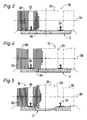
- the various sweeping brushes 10, 15, 16 can be rotated (partly in dash-dotted lines) with respect to their rotating bodies 33 formed by the end faces 38 of sweeping elements 32 shown) can be designed differently.
- the cylindrically shaped rotary body 33 shown in FIG. 3 is particularly suitable for sweeping sleepers 34 made of wood. 4 is particularly suitable for sweeping sleepers 34 made of concrete.
- the rotary body 33 shown in FIG. 5 in connection with a two-block sleeper has a central part 35 which is equipped with sweeping elements 32 which are longer in comparison to the adjacent brush sections 36.
- a rotation shaft 39 is indicated schematically with dash-dotted lines. Of course, any other combination of differently designed rotating bodies 33 is possible.
- the first sweeping brush 10 of the sweeper 1 according to FIG. 3 is designed to initially, if necessary to sweep away existing larger amounts of ballast.
- the middle and last sweeping brushes 15 and 16 are more appropriately designed according to FIG. 5, in order to sweep the ballast deeper out of the area of the track center.
- An advantageous application variant of the sweeper 1 also consists in the fact that, for example, the first and first two sweeping brushes 10 and 10, 15 have a cylindrical rotating body 33 according to FIG. 3, while the last sweeping brush 16 is especially designed for sweeping concrete sleepers according to FIG. 4 is.
- This variant is particularly suitable for sweeping track sections that are made up of sections with different sleepers made of wood and concrete. In such a case, the most appropriate sweeping brush can then be used, possibly also in combination with a further, differently designed sweeping brush.
Landscapes
- Architecture (AREA)
- Civil Engineering (AREA)
- Structural Engineering (AREA)
- Engineering & Computer Science (AREA)
- Machines For Laying And Maintaining Railways (AREA)
- Preliminary Treatment Of Fibers (AREA)
- Vending Machines For Individual Products (AREA)
- Cleaning Of Streets, Tracks, Or Beaches (AREA)
- Soil Working Implements (AREA)
- Finish Polishing, Edge Sharpening, And Grinding By Specific Grinding Devices (AREA)
- Wing Frames And Configurations (AREA)
- Pinball Game Machines (AREA)
- Catching Or Destruction (AREA)
- Feeding Of Articles To Conveyors (AREA)
- Control And Other Processes For Unpacking Of Materials (AREA)
- Manufacturing Of Electric Cables (AREA)
- Emulsifying, Dispersing, Foam-Producing Or Wetting Agents (AREA)
- Manufacture And Refinement Of Metals (AREA)
- Crystals, And After-Treatments Of Crystals (AREA)
- Portable Nailing Machines And Staplers (AREA)
Applications Claiming Priority (2)
| Application Number | Priority Date | Filing Date | Title |
|---|---|---|---|
| AT134493 | 1993-07-08 | ||
| AT1344/93 | 1993-07-08 |
Publications (3)
| Publication Number | Publication Date |
|---|---|
| EP0633355A2 true EP0633355A2 (fr) | 1995-01-11 |
| EP0633355A3 EP0633355A3 (fr) | 1995-06-14 |
| EP0633355B1 EP0633355B1 (fr) | 1998-04-15 |
Family
ID=3511877
Family Applications (1)
| Application Number | Title | Priority Date | Filing Date |
|---|---|---|---|
| EP94890092A Expired - Lifetime EP0633355B1 (fr) | 1993-07-08 | 1994-06-03 | Machine de balayage d'une voie ferrée |
Country Status (15)
| Country | Link |
|---|---|
| US (1) | US5402547A (fr) |
| EP (1) | EP0633355B1 (fr) |
| JP (1) | JP3597218B2 (fr) |
| CN (1) | CN1052051C (fr) |
| AT (1) | ATE165128T1 (fr) |
| AU (1) | AU667013B2 (fr) |
| CZ (1) | CZ279895B6 (fr) |
| DE (1) | DE59405685D1 (fr) |
| ES (1) | ES2117777T3 (fr) |
| FI (1) | FI108662B (fr) |
| PL (1) | PL173871B1 (fr) |
| RU (1) | RU2093637C1 (fr) |
| SK (1) | SK280433B6 (fr) |
| UA (1) | UA27869C2 (fr) |
| ZA (1) | ZA944922B (fr) |
Cited By (3)
| Publication number | Priority date | Publication date | Assignee | Title |
|---|---|---|---|---|
| EP2182115A1 (fr) * | 2008-10-31 | 2010-05-05 | Richter & Müller Handelsgesellschaft mbH | Dispositif de nivellement de ballast |
| WO2011057689A1 (fr) * | 2009-11-11 | 2011-05-19 | Franz Plasser Bahnbaumschinen-Industriegesellschaft Mbh | Machine de traitement d'une voie |
| CZ307057B6 (cs) * | 2016-11-03 | 2017-12-20 | Aurora Engineering s.r.o. | Zařízení pro zpracování a úpravu štěrkového lože |
Families Citing this family (16)
| Publication number | Priority date | Publication date | Assignee | Title |
|---|---|---|---|---|
| EP0743399A1 (fr) * | 1995-05-16 | 1996-11-20 | Speno International S.A. | Equipement pour le nettoyage des voies |
| US5709001A (en) * | 1996-02-05 | 1998-01-20 | Franz Plasser Bahnbaumaschinen Industriegesellschaft M.B.H. | Track work machine |
| DE20009054U1 (de) | 2000-05-19 | 2000-08-10 | ROBEL Bahnbaumaschinen GmbH, 83395 Freilassing | Kehrbürste zum Reinigen der Oberfläche eines aus Schienen und Schwellen gebildeten Gleises |
| RU2244807C2 (ru) * | 2003-02-28 | 2005-01-20 | Омский государственный технический университет | Способ разработки нефтегазового месторождения |
| AT506078B1 (de) * | 2008-02-04 | 2009-06-15 | Plasser Bahnbaumasch Franz | Schotterpflug zum einschottern eines gleises |
| CN101864706B (zh) * | 2009-04-14 | 2013-12-25 | 襄樊金鹰轨道车辆有限责任公司 | 多功能铁路道砟清扫装置 |
| CN101974890A (zh) * | 2010-09-28 | 2011-02-16 | 济南轨道交通装备有限责任公司 | 一种轨道道床清洁装置 |
| US9617692B2 (en) * | 2013-10-10 | 2017-04-11 | Racine Railroad Products, Inc. | Tie plugging machine and method |
| US9920488B2 (en) | 2014-04-08 | 2018-03-20 | Encore Rail Systems, Inc. | Railroad tie plugging system |
| CN104594277A (zh) * | 2014-12-26 | 2015-05-06 | 重庆智仁发电设备有限责任公司 | 铁路道砟清扫机 |
| CN105803993B (zh) * | 2014-12-31 | 2018-02-23 | 中国铁建高新装备股份有限公司 | 一种轨道侧面辅助吸煤、吸沙装置及其相应的轨道除沙车 |
| CN104963248B (zh) * | 2015-07-28 | 2017-01-25 | 中国神华能源股份有限公司 | 用于捣固车的道砟清扫装置和捣固车 |
| CN108114936B (zh) * | 2016-06-28 | 2019-06-14 | 温州乾含节能科技有限公司 | 一种铁轨用支撑设备 |
| CN109082954B (zh) * | 2018-08-17 | 2020-07-17 | 嘉兴市康立德构件股份有限公司 | 一种用于清筛轨道的碎石道碴的装置 |
| AT522721B1 (de) * | 2019-06-26 | 2020-12-15 | Stmg Gmbh | Gleisschotterplaniervorrichtung |
| AT523621B1 (de) | 2020-03-06 | 2024-06-15 | System 7 Ballast Regulator Gmbh | Vorrichtung zum Pflügen für eine gleisfahrbare Schotterplaniermaschine |
Family Cites Families (10)
| Publication number | Priority date | Publication date | Assignee | Title |
|---|---|---|---|---|
| US2869159A (en) * | 1955-02-09 | 1959-01-20 | Kershaw Mfg Co Inc | Railroad track sweeper |
| AT262361B (de) * | 1963-03-01 | 1968-06-10 | Plasser Bahnbaumasch Franz | Fahrbare Vorrichtung zum Behandeln der Schotterbettung von Gleisen |
| US3426379A (en) * | 1966-09-06 | 1969-02-11 | Kershaw Mfg Co Inc | Railroad track cleaning apparatus |
| AT306773B (de) * | 1968-03-20 | 1973-04-25 | Plasser Bahnbaumasch Franz | Fahrbare Maschine zum kontinuierlichen Räumen, Aufnehmen und zum Verteilen des auf dem Gleis liegenden Bettungsschotters |
| JPS565001A (en) * | 1979-06-22 | 1981-01-20 | Iseki Agricult Mach | Harrowing and leveling device in paddy field |
| US4554697A (en) * | 1983-11-16 | 1985-11-26 | Canron Corp. | Ballast brooms |
| IT1181182B (it) * | 1984-06-07 | 1987-09-23 | Danieli Off Mecc | Gruppo profilatore per macchine profilatrici trasferitrici per massicciata |
| DE3872400D1 (de) * | 1988-08-31 | 1992-07-30 | Plasser Bahnbaumasch Franz | Gleisverfahrbare maschine zum verteilen und profilieren des bettungsschotters eines gleises. |
| AT395875B (de) * | 1990-02-22 | 1993-03-25 | Plasser Bahnbaumasch Franz | Gleisbaumaschine zum bearbeiten der schotterbettung |
| AT402952B (de) * | 1991-03-26 | 1997-10-27 | Plasser Bahnbaumasch Franz | Gleisbaumaschine zum kontrollierten absenken einesgleises |
-
1994
- 1994-06-03 AT AT94890092T patent/ATE165128T1/de active
- 1994-06-03 DE DE59405685T patent/DE59405685D1/de not_active Expired - Lifetime
- 1994-06-03 EP EP94890092A patent/EP0633355B1/fr not_active Expired - Lifetime
- 1994-06-03 ES ES94890092T patent/ES2117777T3/es not_active Expired - Lifetime
- 1994-06-15 US US08/260,000 patent/US5402547A/en not_active Expired - Lifetime
- 1994-06-16 PL PL94303860A patent/PL173871B1/pl not_active IP Right Cessation
- 1994-06-23 CZ CZ941551A patent/CZ279895B6/cs not_active IP Right Cessation
- 1994-06-23 RU RU9494021924A patent/RU2093637C1/ru not_active IP Right Cessation
- 1994-06-29 SK SK784-94A patent/SK280433B6/sk not_active IP Right Cessation
- 1994-07-05 UA UA94075609A patent/UA27869C2/uk unknown
- 1994-07-07 ZA ZA944922A patent/ZA944922B/xx unknown
- 1994-07-07 AU AU67307/94A patent/AU667013B2/en not_active Ceased
- 1994-07-07 JP JP15620894A patent/JP3597218B2/ja not_active Expired - Lifetime
- 1994-07-07 FI FI943253A patent/FI108662B/fi not_active IP Right Cessation
- 1994-07-08 CN CN94108133A patent/CN1052051C/zh not_active Expired - Fee Related
Cited By (3)
| Publication number | Priority date | Publication date | Assignee | Title |
|---|---|---|---|---|
| EP2182115A1 (fr) * | 2008-10-31 | 2010-05-05 | Richter & Müller Handelsgesellschaft mbH | Dispositif de nivellement de ballast |
| WO2011057689A1 (fr) * | 2009-11-11 | 2011-05-19 | Franz Plasser Bahnbaumschinen-Industriegesellschaft Mbh | Machine de traitement d'une voie |
| CZ307057B6 (cs) * | 2016-11-03 | 2017-12-20 | Aurora Engineering s.r.o. | Zařízení pro zpracování a úpravu štěrkového lože |
Also Published As
| Publication number | Publication date |
|---|---|
| CN1052051C (zh) | 2000-05-03 |
| CZ279895B6 (cs) | 1995-08-16 |
| PL173871B1 (pl) | 1998-05-29 |
| PL303860A1 (en) | 1995-01-09 |
| AU6730794A (en) | 1995-01-19 |
| AU667013B2 (en) | 1996-02-29 |
| EP0633355B1 (fr) | 1998-04-15 |
| FI943253L (fi) | 1995-01-09 |
| DE59405685D1 (de) | 1998-05-20 |
| CN1103127A (zh) | 1995-05-31 |
| CZ155194A3 (en) | 1995-01-18 |
| SK78494A3 (en) | 1995-02-08 |
| JPH0762601A (ja) | 1995-03-07 |
| ES2117777T3 (es) | 1998-08-16 |
| RU94021924A (ru) | 1996-05-10 |
| ATE165128T1 (de) | 1998-05-15 |
| UA27869C2 (uk) | 2000-10-16 |
| EP0633355A3 (fr) | 1995-06-14 |
| JP3597218B2 (ja) | 2004-12-02 |
| FI108662B (fi) | 2002-02-28 |
| US5402547A (en) | 1995-04-04 |
| ZA944922B (en) | 1995-03-14 |
| SK280433B6 (sk) | 2000-02-14 |
| FI943253A0 (fi) | 1994-07-07 |
| RU2093637C1 (ru) | 1997-10-20 |
Similar Documents
| Publication | Publication Date | Title |
|---|---|---|
| EP0633355B1 (fr) | Machine de balayage d'une voie ferrée | |
| EP0255564B1 (fr) | Machine pour remplacer ou rénover respectivement les rails et les traverses d'une voie existante | |
| DD292492A5 (de) | Fahrbare gleisstopf-, nivellier- und richtmaschine | |
| DD253268A5 (de) | Gleisstopfmaschine | |
| AT3879U2 (de) | Maschine zur erneuerung eines gleises | |
| DD253266A5 (de) | Fahrbare anlage zum reinigen und anschliessenden verdichten der schotterbettung von gleisen | |
| AT402952B (de) | Gleisbaumaschine zum kontrollierten absenken einesgleises | |
| EP1172481B1 (fr) | Machine de renouvellement d'une voie ferrée | |
| DE9215207U1 (de) | Anlage zur Herstellung einer Planumschutzschichte | |
| EP1253247B1 (fr) | Machine pour nettoyer le ballast d' une voie ferrée | |
| EP0416135B1 (fr) | Machine mobile sur rails pour distribuer et profiler le lit de ballast d'une voie ferrée | |
| EP0784121A1 (fr) | Bourreuse pour voie ferrée | |
| DD282260A5 (de) | Kontinuierlich (non-stop) verfahrbare gleisbaumaschine | |
| EP1179635B1 (fr) | Machine de dépose d'une voie ferrée ancienne et de pose d'une nouvelle voie | |
| EP0609647B1 (fr) | Machine pour le renouvellement ou nettoyage d'un lit de ballast | |
| DD284716A5 (de) | Gleisbaumaschine mit gleis-stabilisator | |
| DE2945767C2 (fr) | ||
| DE3106063A1 (de) | Gleisbaumaschine mit einer schotterbett-raeum- und planiervorrichtung | |
| EP1179634B1 (fr) | Machine de renouvellement d'une voie ferrée | |
| EP1195468B1 (fr) | Machine de renouvellement d'une voie ferrée | |
| DE2602161A1 (de) | Gleisstopfmaschine | |
| AT395875B (de) | Gleisbaumaschine zum bearbeiten der schotterbettung | |
| DD253267A5 (de) | Fahrbare anlage zur kontinuierlichen erneuerung der schienen und schwellen eines gleises | |
| EP0665331A1 (fr) | Machine à bourrer les voies ferrées | |
| EP0803610A2 (fr) | Machine et méthode pour placer le ballast d'une voie ferrée |
Legal Events
| Date | Code | Title | Description |
|---|---|---|---|
| PUAI | Public reference made under article 153(3) epc to a published international application that has entered the european phase |
Free format text: ORIGINAL CODE: 0009012 |
|
| AK | Designated contracting states |
Kind code of ref document: A2 Designated state(s): AT CH DE ES FR GB IT LI NL SE |
|
| 17P | Request for examination filed |
Effective date: 19950119 |
|
| PUAL | Search report despatched |
Free format text: ORIGINAL CODE: 0009013 |
|
| AK | Designated contracting states |
Kind code of ref document: A3 Designated state(s): AT CH DE ES FR GB IT LI NL SE |
|
| GRAG | Despatch of communication of intention to grant |
Free format text: ORIGINAL CODE: EPIDOS AGRA |
|
| GRAG | Despatch of communication of intention to grant |
Free format text: ORIGINAL CODE: EPIDOS AGRA |
|
| GRAH | Despatch of communication of intention to grant a patent |
Free format text: ORIGINAL CODE: EPIDOS IGRA |
|
| 17Q | First examination report despatched |
Effective date: 19970909 |
|
| GRAH | Despatch of communication of intention to grant a patent |
Free format text: ORIGINAL CODE: EPIDOS IGRA |
|
| GRAA | (expected) grant |
Free format text: ORIGINAL CODE: 0009210 |
|
| AK | Designated contracting states |
Kind code of ref document: B1 Designated state(s): AT CH DE ES FR GB IT LI NL SE |
|
| REF | Corresponds to: |
Ref document number: 165128 Country of ref document: AT Date of ref document: 19980515 Kind code of ref document: T |
|
| REG | Reference to a national code |
Ref country code: CH Ref legal event code: NV Representative=s name: DIPL.-ING. ETH H. R. WERFFELI PATENTANWALT Ref country code: CH Ref legal event code: EP |
|
| ITF | It: translation for a ep patent filed | ||
| GBT | Gb: translation of ep patent filed (gb section 77(6)(a)/1977) |
Effective date: 19980415 |
|
| REF | Corresponds to: |
Ref document number: 59405685 Country of ref document: DE Date of ref document: 19980520 |
|
| ET | Fr: translation filed | ||
| REG | Reference to a national code |
Ref country code: ES Ref legal event code: FG2A Ref document number: 2117777 Country of ref document: ES Kind code of ref document: T3 |
|
| PLBE | No opposition filed within time limit |
Free format text: ORIGINAL CODE: 0009261 |
|
| STAA | Information on the status of an ep patent application or granted ep patent |
Free format text: STATUS: NO OPPOSITION FILED WITHIN TIME LIMIT |
|
| 26N | No opposition filed | ||
| REG | Reference to a national code |
Ref country code: GB Ref legal event code: IF02 |
|
| PGFP | Annual fee paid to national office [announced via postgrant information from national office to epo] |
Ref country code: ES Payment date: 20110518 Year of fee payment: 18 Ref country code: FR Payment date: 20110601 Year of fee payment: 18 Ref country code: SE Payment date: 20110523 Year of fee payment: 18 Ref country code: CH Payment date: 20110523 Year of fee payment: 18 |
|
| PGFP | Annual fee paid to national office [announced via postgrant information from national office to epo] |
Ref country code: NL Payment date: 20110525 Year of fee payment: 18 Ref country code: GB Payment date: 20110428 Year of fee payment: 18 Ref country code: AT Payment date: 20110511 Year of fee payment: 18 |
|
| PGFP | Annual fee paid to national office [announced via postgrant information from national office to epo] |
Ref country code: DE Payment date: 20110823 Year of fee payment: 18 |
|
| PGFP | Annual fee paid to national office [announced via postgrant information from national office to epo] |
Ref country code: IT Payment date: 20110627 Year of fee payment: 18 |
|
| REG | Reference to a national code |
Ref country code: NL Ref legal event code: V1 Effective date: 20130101 |
|
| REG | Reference to a national code |
Ref country code: SE Ref legal event code: EUG |
|
| REG | Reference to a national code |
Ref country code: CH Ref legal event code: PL |
|
| REG | Reference to a national code |
Ref country code: CH Ref legal event code: PL Ref country code: AT Ref legal event code: MM01 Ref document number: 165128 Country of ref document: AT Kind code of ref document: T Effective date: 20120603 |
|
| GBPC | Gb: european patent ceased through non-payment of renewal fee |
Effective date: 20120603 |
|
| PG25 | Lapsed in a contracting state [announced via postgrant information from national office to epo] |
Ref country code: SE Free format text: LAPSE BECAUSE OF NON-PAYMENT OF DUE FEES Effective date: 20120604 Ref country code: IT Free format text: LAPSE BECAUSE OF NON-PAYMENT OF DUE FEES Effective date: 20120603 |
|
| REG | Reference to a national code |
Ref country code: FR Ref legal event code: ST Effective date: 20130228 |
|
| PG25 | Lapsed in a contracting state [announced via postgrant information from national office to epo] |
Ref country code: LI Free format text: LAPSE BECAUSE OF NON-PAYMENT OF DUE FEES Effective date: 20120630 Ref country code: GB Free format text: LAPSE BECAUSE OF NON-PAYMENT OF DUE FEES Effective date: 20120603 Ref country code: DE Free format text: LAPSE BECAUSE OF NON-PAYMENT OF DUE FEES Effective date: 20130101 Ref country code: NL Free format text: LAPSE BECAUSE OF NON-PAYMENT OF DUE FEES Effective date: 20130101 Ref country code: CH Free format text: LAPSE BECAUSE OF NON-PAYMENT OF DUE FEES Effective date: 20120630 Ref country code: FR Free format text: LAPSE BECAUSE OF NON-PAYMENT OF DUE FEES Effective date: 20120702 |
|
| PG25 | Lapsed in a contracting state [announced via postgrant information from national office to epo] |
Ref country code: AT Free format text: LAPSE BECAUSE OF NON-PAYMENT OF DUE FEES Effective date: 20120603 |
|
| REG | Reference to a national code |
Ref country code: DE Ref legal event code: R119 Ref document number: 59405685 Country of ref document: DE Effective date: 20130101 |
|
| REG | Reference to a national code |
Ref country code: ES Ref legal event code: FD2A Effective date: 20131018 |
|
| PG25 | Lapsed in a contracting state [announced via postgrant information from national office to epo] |
Ref country code: ES Free format text: LAPSE BECAUSE OF NON-PAYMENT OF DUE FEES Effective date: 20120604 |