EP0632530B1 - Battery terminal - Google Patents
Battery terminal Download PDFInfo
- Publication number
- EP0632530B1 EP0632530B1 EP94107787A EP94107787A EP0632530B1 EP 0632530 B1 EP0632530 B1 EP 0632530B1 EP 94107787 A EP94107787 A EP 94107787A EP 94107787 A EP94107787 A EP 94107787A EP 0632530 B1 EP0632530 B1 EP 0632530B1
- Authority
- EP
- European Patent Office
- Prior art keywords
- battery
- post
- clamping
- ring member
- post fitting
- Prior art date
- Legal status (The legal status is an assumption and is not a legal conclusion. Google has not performed a legal analysis and makes no representation as to the accuracy of the status listed.)
- Expired - Lifetime
Links
Images


Classifications
-
- H—ELECTRICITY
- H01—ELECTRIC ELEMENTS
- H01R—ELECTRICALLY-CONDUCTIVE CONNECTIONS; STRUCTURAL ASSOCIATIONS OF A PLURALITY OF MUTUALLY-INSULATED ELECTRICAL CONNECTING ELEMENTS; COUPLING DEVICES; CURRENT COLLECTORS
- H01R11/00—Individual connecting elements providing two or more spaced connecting locations for conductive members which are, or may be, thereby interconnected, e.g. end pieces for wires or cables supported by the wire or cable and having means for facilitating electrical connection to some other wire, terminal, or conductive member, blocks of binding posts
- H01R11/11—End pieces or tapping pieces for wires, supported by the wire and for facilitating electrical connection to some other wire, terminal or conductive member
- H01R11/28—End pieces consisting of a ferrule or sleeve
- H01R11/281—End pieces consisting of a ferrule or sleeve for connections to batteries
- H01R11/283—Bolt, screw or threaded ferrule parallel to the battery post
Definitions
- the present invention relates to a battery terminal mounted to the battery post of a battery installed in a motor vehicle, and relates specifically to a battery terminal whereby the task of securing the battery terminal to the battery post and the task of securing the terminal to the cable connector of the battery terminal can be accomplished by a single thread tightening operation.
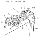
- the battery terminal is made from a single metal member, and comprises a ring-shaped post fitting 2 of which one end is open and which is formed to fit over the battery post 1, clamping members 3a and 3b contiguous on both sides to the open ends of the post fitting 2, and a cable connector 4 contiguous to the closed side of the post fitting 2.
- the post fitting 2 is similarly fit over the battery post 1, and a nut 8 is tightened onto the bolt 7 previously passed through the clamping members 3a and 3b, thus closing the open end of the post fitting 2 contiguous to the clamping members 3a and 3b, and thereby clamping the post fitting 2 securely to the battery post 1.
- this battery terminal design requires separate tasks to secure the battery terminal to the battery post and secure the battery cable terminal to the cable connector of the battery terminal. The separation of these tasks increases the total time required to complete both.
- an object of the present invention is to provide a battery terminal whereby productivity can be increased by completing connection of the cable terminal to the battery terminal and securing the battery terminal to the battery post in a single operation, and whereby the degree of freedom in battery terminal design is increased by positioning the cable connector and the battery cable in a direction preventing interference with other components during assembly of the battery terminal to the battery post.
- a battery terminal for connecting a battery post to a cable comprises a main member, a ring member and a nut.
- the main member is a flat piece of metal and comprises: a post fitting portion having a battery post fitting hole for receiving the battery post therein; a ring support provided continuous to one side of the post fitting portion; a cable connector portion provided continuous to other side of the post fitting portion; and a stud bolt projecting vertically upward from said cable connector portion.
- the ring member placed over said main member comprises: a post fitting portion having a battery post fitting hole for receiving the battery post therein and a truncated cone-shaped clamping piece projecting upward around the inside edge of the battery post fitting hole; a clamping member on one side of the post fitting portion; and a cable connector portion with a bolt hole on other side of the post fitting portion through which said stud bolt is inserted, said cable connector portion being bent at a predetermined angle with respect to said post fitting portion.
- the nut is mounted onto said stud bolt, whereby the battery terminal is assembled such that the end of the clamping member of the ring member is supported by the ring support of the main member, and the post fitting portion of the ring member is inclined relative to the main member, and such that tightening the nut onto the stud bolt clamps the cable terminal to the ring member and simultaneously pushes the clamping piece of the ring member fit at an angle over the battery post down against the battery post.
- a slit is also provided in the clamping member side of the post fitting of the ring member, and a slit continuous to said slit is provided through the widthwise center of the clamping member to divide the clamping member into two right and left clamping pieces.
- the bolt hole provided in the cable connector of the ring member may be an oval.
- a seal member attached to the bottom of the main member is also provided.
- a battery terminal comprises a main member, a ring member and a nut.
- the main member is a flat piece of metal and comprises: a post fitting portion having a battery post fitting hole for receiving the battery post therein; a truncated semiconical clamping piece projecting at one side of the inside face of the battery post fitting hole; a ring support provided continuous to one side of the post fitting portion; a cable connector portion provided continuous to other side of the post fitting portion; and a stud bolt projecting vertically upward from said cable connector portion.
- the ring member placed over said main member comprises: a post fitting portion having a battery post fitting hole for receiving the battery post therein and a truncated semiconical clamping piece projecting at one side of the inside edge of the battery post fitting hole on a side opposite that of the semiconical clamping piece of the main member; a clamping member on one side of the post fitting portion; and a cable connector portion with a bolt hole on other side of the post fitting portion through which said stud bolt is inserted, said cable connector portion being bent at a predetermined angle with respect to said post fitting portion.
- the nut is mounted onto said stud bolt, whereby the battery terminal is assembled such that the end of the clamping member of the ring member is supported by the ring support of the main member, and the post fitting portion of the ring member is inclined relative to the main member, and such that tightening the nut onto the stud bolt clamps the cable terminal to the ring member and simultaneously pushes the semiconical clamping piece of the ring member, which is fit at an angle over the battery post, down to clamp the battery post between the two clamping pieces of the ring member and the main member.
- Figs. 1 - 6 show the first embodiment.
- a battery terminal 10 comprises a main member 11 (Fig. 5) and a ring member 12 (Fig. 4), both made of a conductive metal material.
- a flexible seal member 13 (Fig. 6) is attached to the bottom of the main member 11, and a clamping piece for clamping to the outside surface of the battery post is provided on the ring member 12.
- the main member 11 (Fig. 5) is made from a flat piece with a ring-shaped post fitting 11a having a battery post fitting hole 11e at the center of the main member 11 and the post fitting 11a.
- a rectangular cable connector 11b extends from one side of the post fitting 11a, and a ring support 11c extends from the other side.
- a stud bolt 14 projects vertically upward from the cable connector 11b, and a presser member 11d is bent upward at the end of the ring support 11c.
- the ring member 12 (Fig. 4) is also made from a flat piece with a post fitting 12a having a battery post fitting hole 12h at the center thereof.
- a cone-shaped clamping piece 12i projects upward around the inside edge of the battery post fitting hole 12h.
- a rectangular cable connector 12b extends from one side of the post fitting 12a, and a clamping member 12c extends from the other side.
- the post fitting 12a and cable connector 12b are not provided in a straight line, but offset at a slight angle.
- a bolt hole 12d is also provided in the cable connector 12b.
- a slit 12e provided at the center of the post fitting 12a on the clamping member 12c side continues into the slit 12f running from the bottom of slit 12e through the center and to the outside end of the clamping member 12c.
- the clamping member 12c is thus divided into right and left clamping members 12c-1 and 12c-2 by the slit 12f.
- These right and left clamping members 12c-1 and 12c-2 are contiguous to the two sides of the opening in post fitting 12a, which is similarly divided by the slit 12e.
- the seal member 13 (Fig. 6) attached to the bottom of the main member 11 is shaped essentially like the main member 11: a ring member 13a provided at the center of the seal member 13 is flanked on both sides by flat members 13b and 13c.
- two inverted L-shaped engaging tabs 13d are provided on opposing sides of the ring member 13a, and are spaced to engage the outside edge of the post fitting 11a of the main member 11.
- a third inverted L-shaped engaging tab 13e is provided at the end of the one flat member 13b to engage the end of the cable connector 11b part of the main member 11.
- Engaging members 13f and 13g similarly project up from the end and both sides of the other flat member 13c.
- the end engaging member 13f engages the outside face of the presser member 11d of the main member 11.
- the two side engaging members 13g engage the outside of the right and left clamping members 12c-1 and 12c-2 of the ring member 12 placed on the main member 11.
- the battery terminal 10 is assembled by attaching the seal member 13 to the bottom of the main member 11, placing the ring member 12 on top of the main member 11, and inserting the ends of the clamping members 12c-1 and 12c-2 of the ring member 12 into the presser member 11d of the main member 11 with the outside sides of the clamping members 12c-1 and 12c-2 contacting the engaging members 13g of the seal member 13.
- the bolt hole 12d in the cable connector 12b of the ring member 12 is also passed over the stud bolt 14 projecting from the main member 11.
- the post fitting 12a is at an angle to the cable connector 12b.
- the post fitting 12a is positioning at a rising slope from the pivot point of the presser member 11d stopping the ends of the clamping member 12c, and the cable connector 12b is thus positioned at a downward slope from the post fitting 12a as shown in Fig. 1.
- the assembled battery terminal 10 is then placed over the battery post 1. Specifically, the ring member 13a of the seal member 13, and the battery post fitting holes 11e and 12h of the ring-shaped post fitting 11a of the main member 11 and the post fitting 12a of the ring member 12, respectively, are fit over the battery post 1.
- the inside diameter of the ring member 13a of the seal member 13 and the battery post fitting hole 11e of the main member 11 is greater than the large diameter at the base of the conical battery post 1.
- the conical clamping piece 12i of the ring member 12 is sized to contact the outside face of the battery post 1, and while the clamping piece 12i fits over the top of the battery post 1, it cannot be easily seated.
- the post fitting 12a is also at an angle to the main member 11.
- the ring member 12, as a result, remains at an angle to the battery post 1 as shown in Fig. 1.
- the terminals T1 and T2 to be connected to the battery are slid onto the stud bolt 14, i.e., the bolt hole T1a of the one terminal T1 is fit onto the stud bolt 14 projecting from the cable connector 12b of the ring member 12, and the bolt hole T2a of the other terminal T2 is then fit onto the stud bolt 14 over the first terminal T1.
- a nut 15 is then threaded onto the stud bolt 14 and tightened with an impact wrench or similar tool (not shown in the figures) from above.
- an impact wrench or similar tool (not shown in the figures) from above.
- the nut 15 is tightened, the ring member 12 resting at an upward slope from the main member 11 is pushed down by the nut 15, thus horizontally displacing the post fitting 12a and clamping member 12c.
- the clamping piece 12i of the post fitting 12a fit over the battery post 1 is forced down coaxially to the battery post 1.
- the slit 12e in the clamping piece 12i and the slit 12f in the clamping member 12c allow the clamping members 12c-1 and 12c-2 to spread, thus absorbing the force acting on the clamping piece 12i.
- the seal member 13 While the sides of the clamping members 12c-1 and 12c-2 contact the engaging members 13g of the seal member 13, the seal member 13 is made from a flexible material, thus permitting the engaging members 13g to be elastically deformed when the clamping members 12c-1 and 12c-2 are displaced to the outside. As a result, the seal member 13 is returned to its original shape due to its inherent resiliency when the external force acting on the clamping members 12c-1 and 12c-2 is alleviated, and restores the clamping members 12c-1 and 12c-2 to a gapless state.
- the force spreading the clamping piece 12i is alleviated when the post fitting 12a and clamping member 12c have been pushed down to a horizontal position as shown in Fig. 2 by tightening the nut 15 because the clamping piece 12i of the post fitting 12a is dimensioned to contact the outside face of the battery post 1 when fully seated.
- the force separating the clamping members 12c-1 and 12c-2 connected to the clamping piece 12i is removed, the gap in the slit 12f is eliminated by the elastic restoring force of the engaging members 13g of the seal member 13, and the gap in the slit 12e in the post fitting 12a is also eliminated.
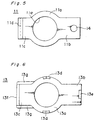
- FIG. 7 - 10 A second embodiment of the present invention is described below with reference to Figs. 7 - 10.
- clamping members fitting over and clamping to the battery post 1 are provided on both the main member 11 and the ring member 12, and a slit is not provided in the clamping member 12c of the ring member 12.
- a semiconical clamping member 11f projects from the inside edge on one side of the battery post fitting hole 11e in the post fitting 11a of the main member 11 (Fig. 9), and a semiconical clamping member 12j projects from the inside edge on the opposite side of the battery post fitting hole 12h in the ring member 12.
- the main member 11, ring member 12, and seal member 13 are assembled as shown in Fig. 7, the clamping member 11f of the main member 11 passes through the battery post fitting hole 12h of the ring member 12, and is therefore opposite the clamping member 12j of the ring member 12.
- the battery post fitting holes in the seal member 13, main member 11, and ring member 12 are fit over the battery post 1.
- the terminals T1 and T2 are fit over the stud bolt 14, and a nut 15 is then tightened using an impact wrench or similar tool.
- the ring member 12 When the nut 15 is tightened, the ring member 12 is forced down, thereby clamping the clamping member 12j of the ring member 12 against one side of the battery post 1 and the clamping member 11f of the main member 11 against the other side of the battery post 1. The battery post 1 is thus clamped between the two clamping members 11f and 12j, and the battery terminal is secured to the battery post.
- the two tasks of securing the cable crimping terminals to the battery terminal and securing the battery terminal to the battery post can be accomplished by a single thread tightening operation, thereby improving job productivity.
- the cables are not connected to the battery terminal when assembling the battery terminal to the battery post, it is not necessary to consider interference between the cables and other components during battery terminal design, and it is sufficient to orient the battery terminal cable connector to prevent interference between the cable and other components when connecting the cable. As a result, the degree of freedom in battery terminal design is also increased.
Landscapes
- Connection Of Batteries Or Terminals (AREA)
Applications Claiming Priority (2)
| Application Number | Priority Date | Filing Date | Title |
|---|---|---|---|
| JP122923/93 | 1993-05-25 | ||
| JP5122923A JP2924561B2 (ja) | 1993-05-25 | 1993-05-25 | バッテリー・ターミナル |
Publications (2)
| Publication Number | Publication Date |
|---|---|
| EP0632530A1 EP0632530A1 (en) | 1995-01-04 |
| EP0632530B1 true EP0632530B1 (en) | 1997-07-23 |
Family
ID=14847956
Family Applications (1)
| Application Number | Title | Priority Date | Filing Date |
|---|---|---|---|
| EP94107787A Expired - Lifetime EP0632530B1 (en) | 1993-05-25 | 1994-05-19 | Battery terminal |
Country Status (4)
| Country | Link |
|---|---|
| US (1) | US5486434A (ja) |
| EP (1) | EP0632530B1 (ja) |
| JP (1) | JP2924561B2 (ja) |
| DE (1) | DE69404393T2 (ja) |
Families Citing this family (42)
| Publication number | Priority date | Publication date | Assignee | Title |
|---|---|---|---|---|
| US5733152A (en) * | 1996-10-09 | 1998-03-31 | Royal Die & Stamping Co., Inc. | Battery terminal adaptor and connector |
| US5800219A (en) * | 1996-12-17 | 1998-09-01 | United Technologies Automotive, Inc. | Stamped battery terminal |
| US6152785A (en) * | 1999-11-23 | 2000-11-28 | Delphi Technologies, Inc. | Battery terminal post connector |
| US6517390B2 (en) * | 2001-01-12 | 2003-02-11 | Hwan-Chang Kim | Connecting terminal for storage battery |
| US6902434B2 (en) * | 2002-07-23 | 2005-06-07 | Cooper Technologies Company | Battery fuse bus bar assembly |
| US6855008B1 (en) | 2003-10-06 | 2005-02-15 | Royal Die & Stamping Co., Inc. | Fuse holder with adjustable terminals |
| US6932650B1 (en) | 2004-03-25 | 2005-08-23 | Royal Die & Stamping Co., Inc. | Fused battery terminal connector |
| JP4706901B2 (ja) * | 2005-02-28 | 2011-06-22 | 住友電装株式会社 | バッテリーターミナル |
| DE102005037422B4 (de) * | 2005-08-08 | 2009-05-07 | Continental Automotive Gmbh | Batteriesensor |
| US7077711B1 (en) * | 2005-08-16 | 2006-07-18 | Yazaki North America, Inc. | Cam lock for electrical terminal |
| JP2008054597A (ja) * | 2006-08-31 | 2008-03-13 | Shimano Inc | 電動リール用バッテリーおよび電動リール用バッテリーセット |
| US20090191454A1 (en) * | 2008-01-30 | 2009-07-30 | Detter Gary C | Pivotally actuated battery clamp terminal |
| ITVI20080006U1 (it) * | 2008-02-28 | 2009-08-29 | Viemme Srl | Connessione elettrica perfezionata |
| US10355264B2 (en) | 2009-09-10 | 2019-07-16 | Cps Technology Holdings Llc | Secondary battery |
| JP5560697B2 (ja) * | 2009-12-23 | 2014-07-30 | 住友電装株式会社 | バッテリーターミナル |
| JP5560698B2 (ja) * | 2009-12-23 | 2014-07-30 | 住友電装株式会社 | バッテリーターミナル |
| EP2372845A1 (en) * | 2010-03-31 | 2011-10-05 | MTA S.p.A. | Clamp for battery post |
| JP6258688B2 (ja) * | 2013-12-12 | 2018-01-10 | 矢崎総業株式会社 | バッテリー端子 |
| JP6272004B2 (ja) * | 2013-12-19 | 2018-01-31 | 矢崎総業株式会社 | バッテリー端子用樹脂部品及びバッテリー端子ユニット |
| JP2015167107A (ja) * | 2014-03-04 | 2015-09-24 | 住友電装株式会社 | バッテリーターミナル |
| JP6160558B2 (ja) * | 2014-05-14 | 2017-07-12 | 住友電装株式会社 | バッテリーターミナル |
| US11458851B2 (en) | 2014-07-03 | 2022-10-04 | The Noco Company | Jump starting apparatus |
| US9007015B1 (en) | 2014-07-03 | 2015-04-14 | The Noco Company | Portable vehicle battery jump start apparatus with safety protection |
| US9608254B1 (en) | 2016-05-26 | 2017-03-28 | Royal Die & Stamping Co., Inc. | Pull bar battery terminal clamp |
| EP3264515B1 (en) | 2016-06-30 | 2019-04-03 | Shenzhen Carku Technology Co., Ltd. | Smart battery jumper cable |
| JP6620716B2 (ja) * | 2016-10-26 | 2019-12-18 | 株式会社オートネットワーク技術研究所 | 配線モジュール |
| US10008789B1 (en) | 2017-07-10 | 2018-06-26 | Royal Die & Stamping, Llc | Angled bolt T-bar battery terminal clamp |
| DE102017219820A1 (de) * | 2017-11-08 | 2019-05-09 | Robert Bosch Gmbh | Selbstsperrende Batteriepolklemme |
| JP6974146B2 (ja) * | 2017-12-06 | 2021-12-01 | 矢崎総業株式会社 | 配索材の接続構造 |
| GB2605117B (en) | 2017-12-14 | 2023-02-15 | Noco Co | Portable vehicle battery jump starter with air pump |
| USD867985S1 (en) | 2017-12-21 | 2019-11-26 | The Noco Company | Combination jump starter and display |
| IT201800003963A1 (it) * | 2018-03-26 | 2019-09-26 | Mta Spa | Morsetto per un terminale maschio di una sorgente di energia elettrica. |
| JP7119762B2 (ja) * | 2018-08-22 | 2022-08-17 | トヨタ自動車株式会社 | 接続モジュール |
| USD913935S1 (en) | 2018-10-01 | 2021-03-23 | The Noco Company | Battery clamp |
| USD997102S1 (en) | 2018-10-03 | 2023-08-29 | The Noco Company | Battery clamp |
| USD913938S1 (en) | 2018-10-03 | 2021-03-23 | The Noco Company | Battery clamp |
| USD913937S1 (en) | 2018-10-03 | 2021-03-23 | The Noco Company | Battery clamp |
| USD984381S1 (en) | 2020-11-25 | 2023-04-25 | The Noco Company | Battery cable assembly for jump starting device |
| USD991185S1 (en) | 2020-12-11 | 2023-07-04 | The Noco Company | Battery cable assembly |
| USD991186S1 (en) | 2020-12-11 | 2023-07-04 | The Noco Company | Battery cable assembly |
| CN114649696A (zh) * | 2020-12-18 | 2022-06-21 | 威卡亚力山大维甘德欧洲两合公司 | 电组件 |
| US11424559B1 (en) * | 2021-05-07 | 2022-08-23 | GM Global Technology Operations LLC | Strain relief for battery cable terminals |
Family Cites Families (9)
| Publication number | Priority date | Publication date | Assignee | Title |
|---|---|---|---|---|
| US1930772A (en) * | 1931-11-16 | 1933-10-17 | Richter Otto | Electrical cable connecter |
| US1968137A (en) * | 1933-07-12 | 1934-07-31 | Allie D Gay | Battery terminal clamp |
| US2067934A (en) * | 1935-07-17 | 1937-01-19 | Edward A Lienhart | Battery connecter |
| DE856473C (de) * | 1943-10-28 | 1952-11-20 | Bayerische Motoren Werke Ag | Vorrichtung zum Befestigen der Kabelschuhe an den Anschlusspolen, insbesondere von Batterien |
| IT1202490B (it) * | 1987-02-09 | 1989-02-09 | Cavis Cavetti Isolati Spa | Struttura di morsetto elettrico,particolarmente studiata per la connessione ai poli di una batteria elettrica per autoveicoli |
| JPH049736A (ja) * | 1990-04-27 | 1992-01-14 | Mazda Motor Corp | 合金薄膜のサンプリング方法 |
| JP2574235Y2 (ja) * | 1992-06-09 | 1998-06-11 | 住友電装株式会社 | バッテリー・ターミナル |
| JP2594027Y2 (ja) * | 1992-06-17 | 1999-04-19 | 住友電装株式会社 | バッテリー・ターミナル |
| JP2587000Y2 (ja) * | 1992-09-10 | 1998-12-14 | 住友電装株式会社 | バッテリー・ターミナル |
-
1993
- 1993-05-25 JP JP5122923A patent/JP2924561B2/ja not_active Expired - Fee Related
-
1994
- 1994-05-09 US US08/239,875 patent/US5486434A/en not_active Expired - Lifetime
- 1994-05-19 EP EP94107787A patent/EP0632530B1/en not_active Expired - Lifetime
- 1994-05-19 DE DE69404393T patent/DE69404393T2/de not_active Expired - Fee Related
Also Published As
| Publication number | Publication date |
|---|---|
| JP2924561B2 (ja) | 1999-07-26 |
| DE69404393D1 (de) | 1997-08-28 |
| JPH06333555A (ja) | 1994-12-02 |
| US5486434A (en) | 1996-01-23 |
| DE69404393T2 (de) | 1998-02-26 |
| EP0632530A1 (en) | 1995-01-04 |
Similar Documents
| Publication | Publication Date | Title |
|---|---|---|
| EP0632530B1 (en) | Battery terminal | |
| US7002076B2 (en) | Electric box extender | |
| US5595511A (en) | Battery terminal | |
| US6178106B1 (en) | Power distribution center with improved power supply connection | |
| US5997341A (en) | Terminal connecting-fixing construction | |
| EP0606068B1 (en) | Battery terminal | |
| US5672442A (en) | Battery terminal and post with rotation inhibiting means | |
| US20030210951A1 (en) | Load cell for securing electronic components | |
| US5620291A (en) | Quick disconnect fastener | |
| US7374464B1 (en) | Quick connection battery terminal | |
| US4708417A (en) | Threadless electric terminal | |
| EP0803935B1 (en) | A terminal metal fitting assembling structure | |
| US6805593B2 (en) | Quick connect battery terminal | |
| US11015742B2 (en) | Cable fastening assembly and method for using same | |
| US10938131B1 (en) | Insert for a battery terminal for increased retention | |
| CN114843804A (zh) | 用于线缆的两件式接地夹 | |
| US5310365A (en) | Terminal connecting device | |
| US5429512A (en) | Terminal arrangement | |
| JPH08293300A (ja) | バッテリー端子 | |
| GB2202294A (en) | Captive fasteners | |
| US11626649B2 (en) | Wedge battery terminal | |
| US20220109134A1 (en) | Battery terminal | |
| JP3060365B2 (ja) | 組合せ端子 | |
| JP3060360B2 (ja) | バッテリ電極用接続端子 | |
| JP3248472B2 (ja) | 配電ボックス |
Legal Events
| Date | Code | Title | Description |
|---|---|---|---|
| PUAI | Public reference made under article 153(3) epc to a published international application that has entered the european phase |
Free format text: ORIGINAL CODE: 0009012 |
|
| AK | Designated contracting states |
Kind code of ref document: A1 Designated state(s): DE GB |
|
| 17P | Request for examination filed |
Effective date: 19950228 |
|
| 17Q | First examination report despatched |
Effective date: 19951222 |
|
| GRAG | Despatch of communication of intention to grant |
Free format text: ORIGINAL CODE: EPIDOS AGRA |
|
| GRAH | Despatch of communication of intention to grant a patent |
Free format text: ORIGINAL CODE: EPIDOS IGRA |
|
| GRAH | Despatch of communication of intention to grant a patent |
Free format text: ORIGINAL CODE: EPIDOS IGRA |
|
| GRAA | (expected) grant |
Free format text: ORIGINAL CODE: 0009210 |
|
| AK | Designated contracting states |
Kind code of ref document: B1 Designated state(s): DE GB |
|
| REF | Corresponds to: |
Ref document number: 69404393 Country of ref document: DE Date of ref document: 19970828 |
|
| PLBE | No opposition filed within time limit |
Free format text: ORIGINAL CODE: 0009261 |
|
| STAA | Information on the status of an ep patent application or granted ep patent |
Free format text: STATUS: NO OPPOSITION FILED WITHIN TIME LIMIT |
|
| 26N | No opposition filed | ||
| REG | Reference to a national code |
Ref country code: GB Ref legal event code: IF02 |
|
| PGFP | Annual fee paid to national office [announced via postgrant information from national office to epo] |
Ref country code: GB Payment date: 20020515 Year of fee payment: 9 |
|
| PG25 | Lapsed in a contracting state [announced via postgrant information from national office to epo] |
Ref country code: GB Free format text: LAPSE BECAUSE OF NON-PAYMENT OF DUE FEES Effective date: 20030519 |
|
| PGFP | Annual fee paid to national office [announced via postgrant information from national office to epo] |
Ref country code: DE Payment date: 20030529 Year of fee payment: 10 |
|
| GBPC | Gb: european patent ceased through non-payment of renewal fee |
Effective date: 20030519 |
|
| PG25 | Lapsed in a contracting state [announced via postgrant information from national office to epo] |
Ref country code: DE Free format text: LAPSE BECAUSE OF NON-PAYMENT OF DUE FEES Effective date: 20041201 |