EP0631789B1 - Vorrichtung zum Gasaustausch, insbesondere Oxygenierung in Blut - Google Patents
Vorrichtung zum Gasaustausch, insbesondere Oxygenierung in Blut Download PDFInfo
- Publication number
- EP0631789B1 EP0631789B1 EP94109061A EP94109061A EP0631789B1 EP 0631789 B1 EP0631789 B1 EP 0631789B1 EP 94109061 A EP94109061 A EP 94109061A EP 94109061 A EP94109061 A EP 94109061A EP 0631789 B1 EP0631789 B1 EP 0631789B1
- Authority
- EP
- European Patent Office
- Prior art keywords
- gas
- blood
- membrane
- oxygen
- pressure
- Prior art date
- Legal status (The legal status is an assumption and is not a legal conclusion. Google has not performed a legal analysis and makes no representation as to the accuracy of the status listed.)
- Expired - Lifetime
Links
- 239000008280 blood Substances 0.000 title claims description 82
- 210000004369 blood Anatomy 0.000 title claims description 82
- 230000001706 oxygenating effect Effects 0.000 title claims 3
- 239000007789 gas Substances 0.000 claims description 139
- 239000012528 membrane Substances 0.000 claims description 80
- QVGXLLKOCUKJST-UHFFFAOYSA-N atomic oxygen Chemical compound [O] QVGXLLKOCUKJST-UHFFFAOYSA-N 0.000 claims description 47
- 239000001301 oxygen Substances 0.000 claims description 47
- 229910052760 oxygen Inorganic materials 0.000 claims description 47
- 239000011148 porous material Substances 0.000 claims description 20
- 239000000203 mixture Substances 0.000 claims description 16
- 238000007872 degassing Methods 0.000 claims description 12
- 238000011144 upstream manufacturing Methods 0.000 claims description 12
- 239000000463 material Substances 0.000 claims description 9
- 229920002492 poly(sulfone) Polymers 0.000 claims description 3
- 229920000036 polyvinylpyrrolidone Polymers 0.000 claims description 3
- 239000001267 polyvinylpyrrolidone Substances 0.000 claims description 3
- 235000013855 polyvinylpyrrolidone Nutrition 0.000 claims description 3
- 239000012530 fluid Substances 0.000 claims 1
- 239000003570 air Substances 0.000 description 26
- 239000007788 liquid Substances 0.000 description 23
- 230000002209 hydrophobic effect Effects 0.000 description 21
- 238000006213 oxygenation reaction Methods 0.000 description 17
- XLYOFNOQVPJJNP-UHFFFAOYSA-N water Substances O XLYOFNOQVPJJNP-UHFFFAOYSA-N 0.000 description 9
- 238000009792 diffusion process Methods 0.000 description 5
- 238000002618 extracorporeal membrane oxygenation Methods 0.000 description 5
- 229920001296 polysiloxane Polymers 0.000 description 5
- 230000001105 regulatory effect Effects 0.000 description 5
- 230000007704 transition Effects 0.000 description 4
- 230000017531 blood circulation Effects 0.000 description 3
- 230000008859 change Effects 0.000 description 3
- 230000007774 longterm Effects 0.000 description 3
- 239000002504 physiological saline solution Substances 0.000 description 3
- 206010001526 Air embolism Diseases 0.000 description 2
- LFQSCWFLJHTTHZ-UHFFFAOYSA-N Ethanol Chemical compound CCO LFQSCWFLJHTTHZ-UHFFFAOYSA-N 0.000 description 2
- 239000004743 Polypropylene Substances 0.000 description 2
- 230000004888 barrier function Effects 0.000 description 2
- 230000015572 biosynthetic process Effects 0.000 description 2
- 230000000875 corresponding effect Effects 0.000 description 2
- 238000001514 detection method Methods 0.000 description 2
- 239000012510 hollow fiber Substances 0.000 description 2
- 238000000034 method Methods 0.000 description 2
- 230000035515 penetration Effects 0.000 description 2
- 229920006395 saturated elastomer Polymers 0.000 description 2
- HLZKNKRTKFSKGZ-UHFFFAOYSA-N tetradecan-1-ol Chemical compound CCCCCCCCCCCCCCO HLZKNKRTKFSKGZ-UHFFFAOYSA-N 0.000 description 2
- 238000009736 wetting Methods 0.000 description 2
- 206010007191 Capillary fragility Diseases 0.000 description 1
- 239000004890 Hydrophobing Agent Substances 0.000 description 1
- -1 Polypropylene Polymers 0.000 description 1
- VMHLLURERBWHNL-UHFFFAOYSA-M Sodium acetate Chemical compound [Na+].CC([O-])=O VMHLLURERBWHNL-UHFFFAOYSA-M 0.000 description 1
- 239000000654 additive Substances 0.000 description 1
- 239000012080 ambient air Substances 0.000 description 1
- 239000000560 biocompatible material Substances 0.000 description 1
- 230000036772 blood pressure Effects 0.000 description 1
- 230000036770 blood supply Effects 0.000 description 1
- 239000003795 chemical substances by application Substances 0.000 description 1
- 230000002596 correlated effect Effects 0.000 description 1
- 230000007547 defect Effects 0.000 description 1
- 238000009795 derivation Methods 0.000 description 1
- 239000008151 electrolyte solution Substances 0.000 description 1
- 239000000706 filtrate Substances 0.000 description 1
- 239000006260 foam Substances 0.000 description 1
- 239000007792 gaseous phase Substances 0.000 description 1
- 238000001631 haemodialysis Methods 0.000 description 1
- 230000000322 hemodialysis Effects 0.000 description 1
- 239000007791 liquid phase Substances 0.000 description 1
- 238000012153 long-term therapy Methods 0.000 description 1
- 229940043348 myristyl alcohol Drugs 0.000 description 1
- 210000000056 organ Anatomy 0.000 description 1
- 230000036284 oxygen consumption Effects 0.000 description 1
- 238000002616 plasmapheresis Methods 0.000 description 1
- 229920002239 polyacrylonitrile Polymers 0.000 description 1
- 229920001155 polypropylene Polymers 0.000 description 1
- 230000008569 process Effects 0.000 description 1
- 239000004627 regenerated cellulose Substances 0.000 description 1
- 239000005871 repellent Substances 0.000 description 1
- 235000017281 sodium acetate Nutrition 0.000 description 1
- 239000001632 sodium acetate Substances 0.000 description 1
- 239000000243 solution Substances 0.000 description 1
- 238000001356 surgical procedure Methods 0.000 description 1
- 238000002560 therapeutic procedure Methods 0.000 description 1
- 238000011282 treatment Methods 0.000 description 1
Images

Classifications
-
- A—HUMAN NECESSITIES
- A61—MEDICAL OR VETERINARY SCIENCE; HYGIENE
- A61M—DEVICES FOR INTRODUCING MEDIA INTO, OR ONTO, THE BODY; DEVICES FOR TRANSDUCING BODY MEDIA OR FOR TAKING MEDIA FROM THE BODY; DEVICES FOR PRODUCING OR ENDING SLEEP OR STUPOR
- A61M1/00—Suction or pumping devices for medical purposes; Devices for carrying-off, for treatment of, or for carrying-over, body-liquids; Drainage systems
- A61M1/14—Dialysis systems; Artificial kidneys; Blood oxygenators ; Reciprocating systems for treatment of body fluids, e.g. single needle systems for hemofiltration or pheresis
- A61M1/16—Dialysis systems; Artificial kidneys; Blood oxygenators ; Reciprocating systems for treatment of body fluids, e.g. single needle systems for hemofiltration or pheresis with membranes
- A61M1/1698—Blood oxygenators with or without heat-exchangers
-
- A—HUMAN NECESSITIES
- A61—MEDICAL OR VETERINARY SCIENCE; HYGIENE
- A61M—DEVICES FOR INTRODUCING MEDIA INTO, OR ONTO, THE BODY; DEVICES FOR TRANSDUCING BODY MEDIA OR FOR TAKING MEDIA FROM THE BODY; DEVICES FOR PRODUCING OR ENDING SLEEP OR STUPOR
- A61M1/00—Suction or pumping devices for medical purposes; Devices for carrying-off, for treatment of, or for carrying-over, body-liquids; Drainage systems
- A61M1/36—Other treatment of blood in a by-pass of the natural circulatory system, e.g. temperature adaptation, irradiation ; Extra-corporeal blood circuits
- A61M1/3607—Regulation parameters
- A61M1/3609—Physical characteristics of the blood, e.g. haematocrit, urea
- A61M1/361—Physical characteristics of the blood, e.g. haematocrit, urea before treatment
-
- A—HUMAN NECESSITIES
- A61—MEDICAL OR VETERINARY SCIENCE; HYGIENE
- A61M—DEVICES FOR INTRODUCING MEDIA INTO, OR ONTO, THE BODY; DEVICES FOR TRANSDUCING BODY MEDIA OR FOR TAKING MEDIA FROM THE BODY; DEVICES FOR PRODUCING OR ENDING SLEEP OR STUPOR
- A61M1/00—Suction or pumping devices for medical purposes; Devices for carrying-off, for treatment of, or for carrying-over, body-liquids; Drainage systems
- A61M1/36—Other treatment of blood in a by-pass of the natural circulatory system, e.g. temperature adaptation, irradiation ; Extra-corporeal blood circuits
- A61M1/3607—Regulation parameters
- A61M1/3609—Physical characteristics of the blood, e.g. haematocrit, urea
- A61M1/3612—Physical characteristics of the blood, e.g. haematocrit, urea after treatment
Definitions
- the invention relates to a device for gas exchange, in particular Oxygenation in blood using a gas exchanger that is through a semipermeable Membrane is divided into a blood chamber and a gas exchange chamber, wherein an extracorporeal blood path through the blood chamber and through the Gas exchange chamber are laid a gas path.
- Microporous membranes are usually used to make hydrophobic membranes used. This is for example in the case of extracorporeal membrane oxygenation (ECMO) the case in which in the extracorporeal circuit, for example in the Performing open heart surgery to oxygenate blood becomes.
- ECMO extracorporeal membrane oxygenation
- ECMO devices are described, for example, in ASAIO, Vol. XXXIV (1988), pages 978-985.
- a hydrophobic oxygenator is described in DE-A-31 29 064, which suggests the use of hydrophobic membrane materials, for example in the form of hollow fibers for oxygenation. Blood is then passed in the extracorporeal circuit on one side of a hydrophobic membrane, while oxygen is supplied in countercurrent on the other side of the membrane, so that a CO 2 / O 2 exchange can take place across the pores of the membrane.
- hydrophobic membranes are known, which are usually be used in the blood oxygenation sector. To make this hydrophobic To make membranes usable for plasmapheresis will be hydrophilized to separate plasma fractions from the blood.
- hydrophobic membranes Two types of hydrophobic membranes are usually used, namely membranes made of a per se hydrophobic material, for example Polypropylene, and membranes, the surface of which with a Hydrophobing agents, for example silicone, have been made hydrophobic.
- a per se hydrophobic material for example Polypropylene
- a Hydrophobing agents for example silicone
- Hydrophobic membranes made of hydrophobic materials, such as PP, have comparatively large pores of several 100 to 1000 nm and are in the form of several 1000 hollow fibers, which results in an active surface of up to 6 m 2 .
- the blood flows either in the hollow filaments or on the outside of the hollow filament, while the gas to be exchanged flows on the opposite side in counterflow.
- These membranes are usually used in heart-lung machines.
- Water-repellent membranes consist of a thin layer Silicone on a porous support structure and are - as explained below - used for long-term ECMO treatment.
- Hydrophobic membranes are compared to siliconized membranes more effective with regard to the diffusion of the gases in the gas-filled pores, since the Diffusion in pores takes place much faster than through liquid interfaces.
- membranes made of hydrophobic porous material have one significant disadvantage in long-term therapy, i.e. in therapy that is about spans a period of more than 6 hours. This disadvantage is Lick the membrane, because the pores, despite their hydrophobic structure fill aqueous plasma components, which leads to hydrophilization or Wetting the surface of the membrane leads.
- the hydrophilization leads on the one hand to free flow of the plasma from the blood to the gas side, so that the plasma Oxygenator can leave in liquid form or as a foam, and on the other hand obstruction of gas diffusion due to the clogging of the membranes with plasma so that the efficiency of the device is drastically reduced. In in such a case, the oxygenator must be replaced.
- silicone membranes are less effective, but prevent one Penetration of plasma and are therefore used in long-term ECMO.
- hydrophobic membranes were used for the extracorporeal removal of CO 2 (ECCO 2 R) from blood.
- CO 2 R CO 2
- hydrophilic membranes for ECMO used, for example in IEEE 13 (1991), pages 1557-1559.
- the oxygenation takes place in several circuits, which are separated from each other with semipermeable membranes.
- the Immediate oxygenation is initially carried out with the usual hydrophobic Oxygenator with oxygen running on one side and the other Side is loaded with aqueous liquid.
- This watery liquid absorbs Sauerstoft in a certain partial pressure and passes it along a hydrophilic membrane to a bloodstream, i.e. it takes place Exchange of liquid with different gas contents along the surface the hydrophilic membrane.
- Such a device therefore uses the Classic hydrophobic membrane for the transfer of gaseous oxygen in an aqueous liquid.
- the invention has for its object a device for gas exchange to provide in the blood, on the one hand, a high exchange rate has and on the other hand can also be used in long-term operation.
- the problem is solved in that the membrane is hydrophilized and is wetted with water during operation and the gas path with oxygen-containing gas operating under positive transmembrane pressure from the gas to the blood side is acted upon.
- hydrophilic membrane are all wettable with water Membranes understood, that is, membranes that consist of one or hydrophilic material containing several components, such as regenerated Cellulose or polysulfone determined with polyvinyl pyrrolidone (PVP) Amounts are hydrophilized.
- PVP polyvinyl pyrrolidone
- Other membrane materials are Polyacrylonitrile, cuprophan, CA and the like. It should be noted that this Membranes have been used for hemodialysis for many years and have proven themselves there.
- Membranes are used, provided they are washable Hydrophilizing agents, such as myristyl alcohol or with a water / ethanol mixture be made hydrophilic. For example, if you put the latter Mixture on, a membrane filled with this mixture can pass directly through Introduction of water or an aqueous electrolytic solution, i.e., all pores are then filled with the aqueous liquid.
- Hydrophilization method using sodium acetate is for example in the DE-A-30 43 073.
- such membranes are used which consist of hydrophilic or made hydrophilic by hydrophilic additives consist.
- Hydrophilic membranes as described, for example, in DE-A-34 26 331 are usually asymmetrical in shape, i.e. she consist of a relatively thin skin (skin) of about 1 ⁇ m, that of a relatively large-pored support structure is supported. Both structures consist of one and the same material, the thin-pored membrane having relatively small pores Diameter (between 2 and 20 nm). This takes place through these pores Gas exchange via the liquid column in the pore, whereby the Molecule in the gas stream at the gas-liquid interface with the in the liquid physically dissolved gas molecule is in equilibrium. In this respect, the liquid film located there serves as a barrier for gases the silicone membrane with the difference that the exchange performance is essential is larger because the diffusion constant of dissolved oxygen in water in the Compared to silicone is much higher.
- the liquid in a pore can, depending on the Pore diameter and the length of the pore at a certain pressure the pore be squeezed out by placing a on the other side of the membrane Gas is applied with a certain excess pressure. As soon as the pressure hits you exceeds a certain value, the liquid is completely pressed out of the pore, so that gas bubbles are visible in the liquid (so-called bubble point pressure).
- This process is used to create hydrophilic membranes, for example in the case of hemodialyzers for the detection of defects (large holes or broken capillaries).
- the bubble point is usually located of such membranes in water at a value above 10 bar, so that with Water-wetted membranes are tight up to 10 bar and acted on with gas can be without fear of gas penetration.
- the gas partial pressure in a liquid depends on the the amount of gas dissolved in the liquid is correlated with that applied External pressure and / or the gas partial pressure of the respective gas component in the Gas mixture (like the component oxygen in air) with the result that over the applied external pressure set the amount of gas to be supplied to the blood can be.
- the oxygen concentration can be determined by the choice of Air / oxygen mixture or the pressure set on this mixture become.
- the membranes are advantageously in Form of hollow threads. On the other hand, however, can also Flat membranes are used.
- the hollow threads have one Outside diameter of 100-400 microns, advantageously about 200 microns, as well an inner diameter of about 80-320 microns.
- the wall thickness is one Range of 10-60 ⁇ m.
- a gas exchange device in particular an oxygenator, usually contains up to 10,000 hollow filaments per unit, so that the entire membrane surface can be up to 10 m 2 .
- the membrane wetted with water serves as a liquid membrane through which the exchange or transfer of the gases from one medium gas to the other medium liquid takes place. Accordingly, free CO 2 in the blood on the membrane surface is exchanged for the gas transferred from the other side of the membrane, which usually consists of air enriched with oxygen in a predetermined ratio.
- the gas is advantageously pressed with a positive TMP (seen from the gas side to the blood side) against the liquid interface in which it physically dissolves with the corresponding partial pressure.
- a transfer of gaseous components is excluded due to the fact that the bubble point is not exceeded at the absolute pressure selected.
- hydrophilic membranes wetted with water there is no risk in the case of the hydrophilic membranes wetted with water that gas bubbles are conveyed directly into the bloodstream through the pores of the membrane and thus could produce an air embolism.
- Such a release of air bubbles can also take place when blood is saturated with oxygen-containing gas a too high TMP compared to ambient pressure arises, so that here too expediently an air sensor downstream of the gas exchange device is provided.
- Such supersaturation depends - as stated - on one high TMP, which is set relative to the two media, while the Supersaturation - considered absolutely to the ambient pressure - occurs.
- the Exchange device upstream of a pump, in particular the blood pump, arranged so that this inevitably creates a negative pressure in the suction area the pump results.
- oxygenation it turns out according to the positive TMP a certain oxygen / air concentration in the Blood that may be oversaturated in the negative pressure area.
- the blood transferred to the pressure side of the pump changes due to the pressure increase inevitably the solubility of the gas in blood, i.e. it dissolves under the increased pressure more gas in the blood than at the lower suction pressure. So can a gas supersaturated solution of the blood by increasing the pressure in one not supersaturated area are transferred so that the formation of gas bubbles with such a device is effectively suppressed.
- Embodiment look downstream of the blood pump, in which the Gas exchange device between a flow restrictor upstream and another pump is arranged downstream, so that a artificial negative pressure area is created.
- only one gas exchange device is provided in the extracorporeal circuit, which is on one side of the membrane with blood to be oxygenated and on the other side with a gas stream with a predetermined O 2 partial pressure (concentration), which, however, are changed during oxygenation can be acted upon.
- the gas stream is supplied with a predetermined or regulated overpressure to the membrane wetted with water in countercurrent, so that CO 2 and the oxygen / air mixture are alternately transferred from one side to the other side of the membrane.
- the supply of the oxygen / air mixture can be controlled as well as regulated.
- the flow rate of the blood and the flow rate as well as the composition of the oxygen / air mixture, including the transmembrane pressure are determined beforehand, predetermined pressure and flow values then being maintained. If regulation takes place, an O 2 sensor is provided in the bloodstream downstream of the gas exchanger, with which the current O 2 concentration is determined. The determined value then serves as the actual value, with which a comparison is then made with a target value, the result of which can be used to change the composition or the excess pressure of the gas mixture.
- the pressure change can take place proportionally or intermittently on a pressure control valve or a gas throttle element.
- the valve While the proportional pressure change keeps the pressure constant according to a certain value, the valve is opened and closed intermittently in the intermittent mode of operation, the pressure either due to the ratio of the opening times of the valve to the closing times or due to the frequency of opening constant opening time is kept constant.
- the regulation of the pressure requires a sensor in the gas area as well as a Control device of the control valve.
- two gas exchangers are provided in the extracorporeal blood circuit, one of which is used for CO 2 exchange, while the other exchanger connected downstream is used for pure oxygenation.
- Air is advantageously applied to the CO 2 exchanger, a TMP of approximately 0 being used.
- the air is continuously fed to the membrane and leaves the gas exchanger on the opposite side.
- the partial pressure of CO 2 is advantageously determined downstream or upstream of the exchanger.
- the signal can be sent to a control unit which controls the flow of air in order to set a certain CO 2 content downstream of the filter.
- the second gas exchanger is for pure oxygenation and can one Have a smaller surface area than the first gas exchanger.
- Oxygen is preferably fed to the oxygenator in dead-end operation, i.e., this oxygenator has no gas outlet.
- the oxygen flow will either controlled or adjusted.
- the Oxygen partial pressure and / or oxygen saturation with the help of a sensor determined downstream and the signal in turn passed to a controller unit that adjusts the oxygen flow accordingly.
- the partial pressure of oxygen obtained or the supersaturation arises according to one from the consumer a defined value (e.g. an oxygen partial pressure of 0.25 bar or an oxygen saturation of 99%).
- the entire system can also be operated in a controlled manner in proportional operation, in which the oxygen flow follows in proportion to the blood flow.
- the CO 2 / O 2 exchange performance of the two exchangers is brought into relation to the blood flow and thus operated in a controlled manner.
- the system according to the invention has the following advantages: Standard or somewhat modified dialyzers can be used which have membranes made of comparatively biocompatible materials, such as polysulfone. The cost savings are significant since dialyzers are less than 10% of the cost of a membrane oxygenator.
- Oxygen consumption is limited to that of the patient is needed.
- the CO 2 filter can also be used to remove liquid without significantly impairing the CO 2 removal.
- the sum of the partial pressures in Blood that leaves the oxygenator reaches atmospheric pressure. This - as explained above - must not be exceeded significantly, since otherwise there is a risk of air embolism.
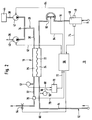
- a gas exchange device is shown schematically at 10 in FIG.
- This gas exchange device has an extracorporeal blood circuit 12, that into a feed line 14 and a discharge line 16 through a gas exchange unit 18 is divided.
- a blood pump 20 is switched on in the feed line.
- the gauze exchange unit 18 is through a semipermeable membrane 22 in a Blood chamber 24 and a gas exchange chamber 26 shared. Through the blood chamber 24, the extracorporeal circuit 12 is placed or at the entrance of the Blood chamber 24 is lead 14 and lead 16 at the exit connected.
- a gas line 28 is placed, which in a Gas supply line 30 and a gas discharge line 32 is divided.
- the end of the gas feed line 30 opens into a gas mixing point 34, to which one Air supply line 36 and an oxygen supply line 38 are connected.
- one Air supply line 36 and an oxygen supply line 38 are connected in the two feed lines 36 and 38.
- gas delivery members 40 and 42 are gas delivery members 40 and 42, respectively switched on. While the air supply line 36 is connected to the ambient air is, the oxygen supply line 38 is connected to an oxygen source 44.
- a drip chamber 46 is also switched on, one Has gas safety sensor 48.
- the feed line 14 has a first pressure sensor adjacent to the blood chamber 24 50 to determine the pressure in the blood.
- a second pressure sensor 52 is provided in the gas discharge line 32, with which the gas pressure in the gas line can be determined.
- the gas exchange device 10 is controlled by means of a control unit 56.
- the control unit 56 is connected to the blood pump via control lines 58-64 20, the terminal arrangement 54, the first gas delivery element 40 and the second Gas delivery member 42 connected.
- Pressure sensors 50 and 52 indicate signals via signal lines 66 and 68 a TMP determination unit 70, whose signal on the signal line 72 the control unit 56 is switched. Furthermore, the control unit 56 is via a Signal line 74 connected to the gas safety sensor 48.
- a CO 2 sensor 76 can be provided in the gas discharge line 32 and is connected to the control unit 56 via a signal line 78.
- the gas exchange device 10 is operated as follows.
- the extracoporal circuit 12 is connected to a patient before connection filled with a sterile physiological saline solution, so that - as at the beginning explained - the hydrophilic membrane 22 is wetted.
- the extracorporeal circuit 12 is then attached to the patient connected and the blood pump 20 at a predetermined speed put into operation by the control unit 56. Then there is a positive one Pressure in the supply line 14 downstream of the blood pump 20 and upstream of the Gas exchange unit 18, which is continuously determined by the pressure sensor 50 and is delivered to the TMP determination unit 70.
- the control unit 50 also takes the first gas conveying element 40 for supply of air in a predetermined manner in operation and leads it to the gas mixing point 34 to. Furthermore, the second gas delivery unit 42 is operated in a predetermined manner put into operation and promotes a predetermined amount of oxygen to Gas mixing point 34, at which an oxygen-air mixture with a predetermined Composition mixed and via the gas feed line 30 Gas exchange chamber 26 is supplied.
- the gas pressure that is applied to the membrane 22 is determined by means of the controllable terminal arrangement 54 and set with the pressure sensor 52nd determined, which also outputs its signal to the TMP determination unit 70 in the transmembrane pressure (TMP) determined and given to the control unit 56 becomes.
- TMP transmembrane pressure
- an oxygen supply of approximately 50 Nml / min takes place, at the same time essentially equal amounts of CO 2 being removed from the blood.
- the CO 2 content can optionally be determined via the gas delivery rate of the gas delivery members 40 and 42 and the CO 2 sensor 76 and set for control purposes.
- the one shown in FIG. 1 works Device 10 downstream of blood pump 20 in the overpressure range, i.e. at the At the entrance to the blood chamber 24 there is blood with excess pressure and at the exit of the Blood chamber usually delivers blood at ambient pressure. After yourself Dissolves more gas in the blood at overpressure than at normal pressure care should be taken to ensure that the blood does not become too saturated Oxygenation occurs, which leads to the formation of gas bubbles from the blood chamber 24 could lead.
- the TMP is therefore to avoid alarm situations adjust that such overpressure conditions do not arise.
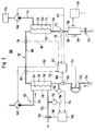
- FIG. 2 shows another Gas exchange device 10, the structure of which is up to the arrangement of the Blood pump 82 is identical to device 10 according to FIG. 1, so that for same parts the same reference numerals are used as in Figure 1.
- the blood pump 82 is downstream of the gas exchange unit 18 in the discharge line 16 however, arranged upstream of the pressure chamber 46 and via a control line 84 connected to the control unit 56.
- the gas exchange unit 18 is located in the suction or negative pressure area of the blood pump 82 with the result that downstream of the blood pump 82, the blood enriched with gas onto the Ambient pressure is raised, so that inevitably the above described supersaturation problem does not apply.
- FIG. 3 shows a third embodiment of a gas exchange device 100 shown, which has an extracorporeal blood circuit 102, which into a Lead 104, a transition line 106 and a derivative 108 is divided.
- a blood pump 110 is switched on in the feed line 104.
- One end of the lead 104 can be connected to a patient, not shown, while the other end is connected to a CO 2 exchanger, which has a semipermeable hydrophilized membrane 114, which the CO 2 exchanger into a blood chamber 116 and a degassing chamber 118 Splits.
- a degassing path 120 is laid through the degassing chamber 118 and is divided into a degassing supply line 122 and a degassing line 124.
- the transition line 106 goes off and is on connected at its other end to an oxygenator 128, which is also through a hydrophilized semipermeable membrane 130 into a blood chamber 132 and an oxygenation chamber 134 is divided.
- the transition line 106 opens thereby into the blood chamber 132.
- this blood chamber passes the derivation 108, into which a drip chamber 136 is switched on, which with a gas safety sensor 138 is equipped.
- a safety clamp 140 Downstream of the drip chamber 136 is a safety clamp 140 on the discharge line 108 provided.
- An oxygenation line 142 opens into the oxygenation chamber 134 advantageously has no drain line and thus in dead-end operation is operated.
- the oxygenation line 142 is connected to an oxygen source 144 connected and has an oxygen delivery member 146.
- a similar air conveying device 148 is at the entrance of the degassing line 120 provided over which air is conveyed.
- These conveyors can be used as pumps or if the gas to be pumped is already supplied with overpressure, be designed as gas pressure control valves or gas flow control valves.
- a first pressure sensor 150 is provided upstream of the CO 2 exchanger in the blood supply line 104 in order to determine the blood pressure in the supply line.
- a second pressure sensor 152 is upstream of the degassing line 124 Throttle 126 provided. Both pressure sensors 150 and 152 transmit Control lines 154 and 156 send their signal to a control unit 158, which the Determines transmembrane pressure and the determined transmembrane pressure with a preset value and compares it via the control line 160 Gas throttle element 126 adjusted accordingly. On the other hand, however, it can also the delivery rate of the blood pump 110 can be adjusted accordingly.
- the transmembrane pressure in the CO 2 exchanger 112 is usually set so that the two partial pressures cancel each other out, so that the transmembrane pressure is approximately zero. If necessary, there may be an overpressure on the blood side if excess liquid is to be removed, which is then removed through the gas discharge line 124 serving as the filtrate line.
- a main control unit 162 which controls the blood pump 110 via the control line 164 and the air delivery element 148 via a control line 166 in accordance with a predetermined CO 2 removal rate.
- a CO 2 sensor can advantageously be provided either upstream or downstream of the CO 2 exchanger 112 in the feed line 104 or in the transition line 106 as a sensor 165 or 167, which are connected to the main control unit 162 via signal lines 168 or 170.
- the air flow to be supplied can then be set on the air conveying element 148 or on the throttle unit 126 with a known transmembrane pressure.
- the main control unit 162 is also connected to the via a control line 172 Oxygen delivery device 146 connected and sets this to a predetermined Value.
- an oxygen sensor 174 is provided downstream of the oxygenator 128 in the discharge line 108, the signal of which is connected to the main control unit 162 via the signal line 176. If the current oxygen content in the blood is determined with the oxygen sensor 174, this actual signal can be compared with a target value in the main control unit 162, which then regulates the O 2 delivery device in accordance with the comparison result carried out.
- the air detector 138 is connected via a safety controller 139, which at Detection of air closes the clamp 140 and the entire assembly in the transferred to safe condition.
- the device according to FIG. 3 is operated as follows.
- the patient After filling with the physiological saline solution, the patient is transferred to the extracorporeal circuit 102 connected and the blood pump 110 with a predetermined speed put into operation.
- the feed then takes place of air and oxygen in a predetermined ratio or regulated via the gas delivery organs 146 and 148.
- the transmembrane pressure is determined in the area of the CO 2 exchanger 112 by means of the pressure sensors 150 and 152, and the gas throttle arrangement 126 is set such that the transmembrane pressure is approximately zero.
- the CO 2 exchanger itself can be adjusted by the delivery rate of the gas delivery device 148, either empirically or by determining CO 2 upstream by means of the CO 2 sensor 164 or downstream by means of the CO 2 sensor 166 and by corresponding control
- the ascertained actual value can be compared with a preset target value on the gas delivery element 148.
- oxygenation in the oxygenator 128 is carried out either empirically or in a controlled manner. If a control is carried out, the oxygen overpressure to be set is kept constant in a predetermined manner by means of the O 2 conveying element 146, so that the oxygenation of blood takes place across the membrane 130. On the other hand, however, the oxygen content in the blood downstream of the oxygenator 128 can also be determined by means of the O 2 sensor 174. The determined actual value can then be compared with a preset target value, so that the O 2 conveying element 146 can be regulated accordingly.
- the oxygenator 128 has a smaller membrane surface than the CO 2 degasser 112, which is usually about 1.8 m 2 , while the oxygenator usually has a membrane surface of about 1 m 2 .
- Oxygen partial pressures are around 0.25 bar, while oxygen saturation is up to 99%.
- a further oxygen sensor 178 can also be provided upstream of the oxygenator 128, which is connected to the main control unit 162 via a further signal line 180.
- This O 2 sensor can additionally or also be used without the O 2 sensor 174 for control or regulation purposes.
Landscapes
- Health & Medical Sciences (AREA)
- Heart & Thoracic Surgery (AREA)
- Vascular Medicine (AREA)
- Life Sciences & Earth Sciences (AREA)
- General Health & Medical Sciences (AREA)
- Anesthesiology (AREA)
- Biomedical Technology (AREA)
- Hematology (AREA)
- Veterinary Medicine (AREA)
- Animal Behavior & Ethology (AREA)
- Engineering & Computer Science (AREA)
- Public Health (AREA)
- Cardiology (AREA)
- Emergency Medicine (AREA)
- Urology & Nephrology (AREA)
- External Artificial Organs (AREA)
- Separation Using Semi-Permeable Membranes (AREA)
Description
Es können Standard- oder etwas modifizierte Dialysatoren eingesetzten werden, die Membranen aus vergleichsweise biokompatiblen Materialien, wie Polysulfon, besitzen. Erheblich sind dabei die Kosteneinsparungen, da Dialysatoren unter 10 % der Kosten eines Membranoxygenators liegen.
Claims (9)
- Vorrichtung (10, 100) zum extrakorporalen Gasaustausch, insbesondere Oxygenieren von Blut mit wenigstens einem Gasaustauscher (18, 118, 128), der durch eine semipermeable Membran (22, 114, 130) in eine Blutkammer (24, 116, 132) und eine Gasaustauschkammer (26, 118, 134) geteilt ist, wobei durch die Blutkammer (26, 116, 132) ein extrakorporaler Blukreislauf (12, 102) und durch die Gasaustauschkammer (26, 118, 134) ein Gasweg (28, 120, 142) gelegt sind, und mit einer in den extrakorporalen Kreislauf (12, 102) eingeschalteten Blutpumpe (20, 82, 110), dadurch gekennzeichnet, daß die Membran (22, 114, 130) hydrophil oder hydrophiliert ist, so daß die Poren mit einer wäßriger Flüssigkeit benetzbar sind und der Gasweg (26, 28, 32; 142, 134) mit sauerstoffhaltigem Gas unter positivem Transmembrandruck von der Gas- zur Blutseite beaufschlagbar ist.
- Vorrichtung nach Anspruch 1, dadurch gekennzeichnet, daß die Blutpumpe (20, 82) stromauf oder stromab des Gasaustauschers (18) angeordnet ist.
- Vorrichtung nach Anspruch 1 oder 2, dadurch gekennzeichnet, daß im extrakorporalen Blutkreislauf (102) ein erster Gasaustauscher (112) als CO2-Austauscher und ein zweiter Gasaustauscher (128) als Oxygenator aufeinanderfolgend angeordnet sind.
- Vorrichtung nach Anspruch 3, dadurch gekennzeichnet, daß in die Entgasungskammer (116) des ersten Gasaustauschers (112) ein Entgasungsweg (120) gelegt ist, der auf der Zuführungsseite mit einem steuerbaren Luftförderorgan (148) und auf der Abluftseite mit einem veränderbaren Gasdrosselorgan (126) versehen ist und der Transmembrandruck an der Membran (114) des ersten Gasaustauschers (112) mit der Transmembrandruck-Steuereinheit (158) einstellbar ist.
- Vorrichtung nach Anspruch 3, dadurch gekennzeichnet, daß der zweite Gasaustauscher (128) mit einer Sauerstoffquelle (144) über eine Oxygenierungsleitung (142) verbunden ist, in die ein steuerbares Sauerstoff-Förderorgan (146) eingeschaltet ist.
- Vorrichtung nach einem der Ansprüche 3 - 5, dadurch gekennzeichnet, daß im extrakorporalen Blutkreislauf (102) wenigstens ein CO2-Sensor (164, 166) vorgesehen ist, dessen Signal als Ist-Wert auf eine Hauptsteuereinheit (162) geschaltet ist, die den Ist-Wert mit einem Soll-Wert vergleicht und aufgrund des Vergleichsergebnisses den Gasdurchfluß des ersten Gasaustauschers (112) regelt.
- Vorrichtung nach einem der Ansprüche 3 - 6, dadurch gekennzeichnet, daß im extrakorporalen Blutkreislauf (102) wenigstens ein O2-Sensor (174) vorgesehen ist, dessen Signal als Ist-Wert auf die Hauptsteuereinheit (162) geschaltet ist, die den Ist-Wert mit einem Soll-Wert vergleicht und aufgrund des Vergleichsergebnisses den am O2-Förderorgan (146) einstellbaren O2-Fluß regelt.
- Vorrichtung nach einem der Ansprüche 1 - 7, dadurch gekennzeichnet, daß die Membran (22, 114, 130) aus einem hydrophilen Material, insbesondere einem Gemisch von Polysulfon und Polyvinylpyrrolidon besteht.
- Vorrichtung nach einem der Ansprüche 1 - 8, dadurch gekennzeichnet, daß die Membran (22, 114, 130) asymmetrisch ist und eine mikroporöse Hautschicht und eine grobporige Stützschicht aufweist, wobei die mittlere Porengröße in der Hautschicht zwischen 2 und 20 nm liegt und die Starke der Hautschicht höchstens bei mehreren µm liegt.
Applications Claiming Priority (2)
| Application Number | Priority Date | Filing Date | Title |
|---|---|---|---|
| DE4320198 | 1993-06-18 | ||
| DE4320198A DE4320198C1 (de) | 1993-06-18 | 1993-06-18 | Vorrichtung zum Gasaustausch, insbesondere zum Oxygenieren von Blut |
Publications (3)
| Publication Number | Publication Date |
|---|---|
| EP0631789A2 EP0631789A2 (de) | 1995-01-04 |
| EP0631789A3 EP0631789A3 (de) | 1995-05-24 |
| EP0631789B1 true EP0631789B1 (de) | 1999-09-01 |
Family
ID=6490613
Family Applications (1)
| Application Number | Title | Priority Date | Filing Date |
|---|---|---|---|
| EP94109061A Expired - Lifetime EP0631789B1 (de) | 1993-06-18 | 1994-06-14 | Vorrichtung zum Gasaustausch, insbesondere Oxygenierung in Blut |
Country Status (5)
| Country | Link |
|---|---|
| US (1) | US5695717A (de) |
| EP (1) | EP0631789B1 (de) |
| JP (1) | JPH07136251A (de) |
| DE (2) | DE4320198C1 (de) |
| ES (1) | ES2138011T3 (de) |
Families Citing this family (50)
| Publication number | Priority date | Publication date | Assignee | Title |
|---|---|---|---|---|
| USRE37379E1 (en) | 1991-02-14 | 2001-09-18 | Wayne State University | High pressure gas exchanger |
| US6312647B1 (en) | 1994-12-09 | 2001-11-06 | Wayne State University | Method for enriching a fluid with oxygen |
| US6676900B1 (en) | 1994-12-09 | 2004-01-13 | Therox, Inc. | Method for the preparation and delivery of gas-enriched fluids |
| US6607698B1 (en) | 1997-08-15 | 2003-08-19 | Therox, Inc. | Method for generalized extracorporeal support |
| US5893838A (en) * | 1997-08-15 | 1999-04-13 | Therox, Inc. | System and method for high pressure delivery of gas-supersaturated fluids |
| US6350411B1 (en) * | 1998-03-23 | 2002-02-26 | Celgard Inc. | Microporous hollow fiber blood oxygenator |
| DE19820158A1 (de) | 1998-05-06 | 1999-11-11 | Convergenza Ag Vaduz | Verfahren und Vorrichtung zur Blutoxygenierung |
| US6602467B1 (en) | 1998-07-24 | 2003-08-05 | Therox, Inc. | Apparatus and method for blood oxygenation |
| US7759113B2 (en) | 1999-04-30 | 2010-07-20 | The General Hospital Corporation | Fabrication of tissue lamina using microfabricated two-dimensional molds |
| US6759008B1 (en) | 1999-09-30 | 2004-07-06 | Therox, Inc. | Apparatus and method for blood oxygenation |
| US6890482B2 (en) | 1999-09-30 | 2005-05-10 | Therox, Inc. | Apparatus for blood oxygenation |
| US6387324B1 (en) | 1999-09-30 | 2002-05-14 | Therox, Inc. | Apparatus and method for blood oxygenation |
| JP2001178817A (ja) * | 1999-12-24 | 2001-07-03 | Terumo Corp | 人工腎臓用装置およびこれを用いた品質評価装置ならびに流体回路 |
| US7776021B2 (en) * | 2000-04-28 | 2010-08-17 | The Charles Stark Draper Laboratory | Micromachined bilayer unit for filtration of small molecules |
| DE20011060U1 (de) | 2000-06-23 | 2000-09-28 | JOSTRA AG, 72145 Hirrlingen | Vorrichtung zur Unterstützung der Lungenfunktion eines Patienten |
| DE10034098C2 (de) * | 2000-07-13 | 2002-11-21 | Fresenius Medical Care De Gmbh | Hydrophobe mikroporöse Hohlfasermembran und Verfahren zur Herstellung dieser Membran sowie deren Verwendung in der Membranoxygenierung |
| US7008535B1 (en) | 2000-08-04 | 2006-03-07 | Wayne State University | Apparatus for oxygenating wastewater |
| US6730267B2 (en) * | 2001-02-09 | 2004-05-04 | Cardiovention, Inc. | Integrated blood handling system having active gas removal system and methods of use |
| US6613280B2 (en) * | 2001-03-20 | 2003-09-02 | Therox, Inc. | Disposable cartridge for producing gas-enriched fluids |
| US6582387B2 (en) | 2001-03-20 | 2003-06-24 | Therox, Inc. | System for enriching a bodily fluid with a gas |
| AU2003275140A1 (en) * | 2002-09-23 | 2004-04-08 | Massachusetts Institute Of Technology | Theree-dimensional construct for the design and fabrication of physiological fluidic networks |
| EP1589814B1 (de) | 2003-01-16 | 2009-08-12 | The General Hospital Corporation | Verwendung von dreidimensionalen, mikrogefertigten, mittels gewebetechnologie hergestellten systemen für pharmakologische anwendungen |
| WO2005034624A2 (en) * | 2003-05-21 | 2005-04-21 | The General Hospital Corporation | Microfabricated compositions and processes for engineering tissues containing multiple cell types |
| US8097456B2 (en) * | 2003-08-18 | 2012-01-17 | The Charles Stark Draper Laboratory | Nanotopographic compositions and methods for cellular organization in tissue engineered structures |
| GB0412315D0 (en) * | 2004-06-03 | 2004-07-07 | Chemcept Ltd | Blood/air mass exchange apparatus |
| EP1649883A1 (de) * | 2004-10-19 | 2006-04-26 | MRI S.r.l. Società Unipersonale | Vorrichtung zur Entfernung von Kohlendioxid aus dem Blut oder aus einer Flüssigkeit kommend aus dem Herzkreislaufsystem eines Patienten |
| EP1649882A1 (de) * | 2004-10-19 | 2006-04-26 | MRI S.r.l. Società Unipersonale | Vorrichtung zur Entfernung von Kohlendioxid aus dem Blut |
| JP4562490B2 (ja) * | 2004-10-26 | 2010-10-13 | 泉工医科工業株式会社 | 人工肺ガス交換モニタ |
| SE529519C2 (sv) * | 2005-03-24 | 2007-09-04 | Sifr 2000 Ab | Kontroll av bubbelbildning vid extrakorporeal cikulation |
| GB2437254B (en) * | 2006-04-13 | 2010-11-17 | Haemair Ltd | Blood/air mass exchange apparatus |
| US8585968B2 (en) * | 2006-04-21 | 2013-11-19 | Scott W. Morley | Method and system for purging moisture from an oxygenator |
| JP4821466B2 (ja) * | 2006-07-03 | 2011-11-24 | 富士ゼロックス株式会社 | 液滴吐出ヘッド |
| EP3192369B1 (de) * | 2007-04-12 | 2018-12-12 | The General Hospital Corporation | Biomimetisches gefässnetz |
| EP2200931B1 (de) * | 2007-09-19 | 2017-06-07 | The Charles Stark Draper Laboratory, Inc. | Mikrofluidstrukturen mit kreisförmigem querschnitt |
| US9595206B2 (en) | 2008-02-11 | 2017-03-14 | The General Hospital | System and method for in vitro blood vessel modeling |
| US8545754B2 (en) | 2009-04-23 | 2013-10-01 | Medtronic, Inc. | Radial design oxygenator with heat exchanger |
| DE102009054395A1 (de) * | 2009-11-24 | 2011-06-01 | Fresenius Medical Care Deutschland Gmbh | Verfahren zum Anpassen von Grenzwertfenstern, Steuervorrichtung, medizinische Behandlungsvorrichtung und medizinische Überwachungsvorrichtung |
| DE102009060489A1 (de) * | 2009-12-29 | 2011-06-30 | Uhde GmbH, 44141 | Vorrichtung und Verfahren zur Regelung der Sauerstoffpermeation durch nicht-poröse Sauerstoffanionen leitende keramische Membranen und deren Verwendung |
| EP2692371B1 (de) * | 2011-03-31 | 2015-11-25 | Terumo Kabushiki Kaisha | Künstliche lunge und extrakorporaler kreislauf |
| CN104039135B (zh) | 2011-11-10 | 2016-01-20 | 奥加诺克斯有限责任公司 | 器官灌注系统 |
| US20140377849A1 (en) | 2011-11-10 | 2014-12-25 | Arganox Limited | Organ perfusion systems |
| GB201119420D0 (en) * | 2011-11-10 | 2011-12-21 | Organox Ltd | Oxygen supply for organ perfusion systems |
| WO2014162335A1 (ja) | 2013-04-01 | 2014-10-09 | テルモ株式会社 | 循環装置及びその制御方法 |
| JP6170603B2 (ja) * | 2016-09-01 | 2017-07-26 | テルモ株式会社 | 循環装置及びその制御方法 |
| US10391226B2 (en) * | 2017-02-07 | 2019-08-27 | International Business Machines Corporation | Air bubble removal from extracorporeal blood via chemical entrapment of nitrogen |
| JP6483874B1 (ja) * | 2018-01-18 | 2019-03-13 | 日機装株式会社 | 圧力検出器の調整装置 |
| GB2584109A (en) * | 2019-05-21 | 2020-11-25 | Haemair Ltd | Control system |
| JP2023525463A (ja) * | 2020-04-07 | 2023-06-16 | ジーアイエス ベンチャーズ インコーポレイテッド | 障害または外傷患者に静脈血の短期的緊急酸素化を提供するためのi.v.流体への溶存酸素の注入 |
| DE102021129141A1 (de) | 2021-11-09 | 2023-05-11 | Rheinisch-Westfälische Technische Hochschule (RWTH) Aachen, Körperschaft des öffentlichen Rechts | Anreicherung von Fluiden unter Druck mit Anreicherungsgas |
| DE102023114312A1 (de) * | 2023-05-31 | 2024-12-05 | Rheinisch-Westfälische Technische Hochschule Aachen, abgekürzt RWTH Aachen, Körperschaft des öffentlichen Rechts | Vorrichtung und Verfahren für den Gasaustausch zwischen einem ersten Austauschmedium und einem zweiten gasförmigen Austauschmedium |
Family Cites Families (17)
| Publication number | Priority date | Publication date | Assignee | Title |
|---|---|---|---|---|
| DE3043073C2 (de) * | 1980-11-14 | 1984-07-05 | Fresenius AG, 6380 Bad Homburg | Filtrationsmembran und Verfahren zur Hydrophilierung |
| DE3129064A1 (de) * | 1981-07-23 | 1983-02-10 | Akzo Gmbh, 5600 Wuppertal | Verfahren und vorrichtung zur blutoxygenation |
| JPS58155865A (ja) * | 1982-03-12 | 1983-09-16 | 株式会社クラレ | 血漿処理用中空糸膜 |
| EP0111499A1 (de) * | 1982-06-14 | 1984-06-27 | Baxter Travenol Laboratories, Inc. | Befeuchtbare hydrophobe hohlfasern |
| US4906375A (en) * | 1984-07-14 | 1990-03-06 | Fresenius, Ag | Asymmetrical microporous hollow fiber for hemodialysis |
| DE3426331A1 (de) * | 1984-07-17 | 1986-01-30 | 6380 Bad Homburg Fresenius AG | Asymmetrische mikroporoese hohlfaser fuer die haemodialyse sowie verfahren zu ihrer herstellung |
| US4828543A (en) * | 1986-04-03 | 1989-05-09 | Weiss Paul I | Extracorporeal circulation apparatus |
| JPS63229061A (ja) * | 1987-03-18 | 1988-09-22 | テルモ株式会社 | 膜型人工肺とその製造方法 |
| DE3720665A1 (de) * | 1987-06-23 | 1989-01-05 | Schael Wilfried | Vorrichtung zur haemodialyse und haemofiltration |
| AU611244B2 (en) * | 1987-12-25 | 1991-06-06 | Terumo Kabushiki Kaisha | Medical instrument |
| US5131928A (en) * | 1990-04-09 | 1992-07-21 | The Standard Oil Company | High pressure facilitated membranes for selective separation and process for the use thereof |
| DE4028311C1 (en) * | 1990-09-06 | 1991-12-05 | Fresenius Ag, 6380 Bad Homburg, De | Extracorporal blood carbon di:oxide removal arrangement - has feeder line connected to infusion device via which acidic infusion soln. is delivered |
| IT1244805B (it) * | 1990-11-22 | 1994-09-05 | Roerig Farmaceutici Italiana S | Circuito extracorporeo di plasmaferesi ad ago singolo |
| US5211850A (en) * | 1991-07-26 | 1993-05-18 | Research Medical, Inc. | Plasma filter sorbent system for removal of components from blood |
| FR2680318B1 (fr) * | 1991-08-14 | 1994-01-21 | Hospal Industrie | Rein artificiel et procede de commande. |
| US5244930A (en) * | 1991-12-13 | 1993-09-14 | Brigham And Women's Hospital | Biphasic foam blood mass transfer device |
| WO1993011807A1 (en) * | 1991-12-13 | 1993-06-24 | Brigham And Women's Hospital | Biphasic foam blood mass transfer device |
-
1993
- 1993-06-18 DE DE4320198A patent/DE4320198C1/de not_active Expired - Fee Related
-
1994
- 1994-06-14 ES ES94109061T patent/ES2138011T3/es not_active Expired - Lifetime
- 1994-06-14 DE DE59408680T patent/DE59408680D1/de not_active Expired - Lifetime
- 1994-06-14 EP EP94109061A patent/EP0631789B1/de not_active Expired - Lifetime
- 1994-06-20 JP JP6137683A patent/JPH07136251A/ja active Pending
-
1996
- 1996-11-15 US US08/751,040 patent/US5695717A/en not_active Expired - Lifetime
Also Published As
| Publication number | Publication date |
|---|---|
| ES2138011T3 (es) | 2000-01-01 |
| JPH07136251A (ja) | 1995-05-30 |
| DE59408680D1 (de) | 1999-10-07 |
| US5695717A (en) | 1997-12-09 |
| EP0631789A3 (de) | 1995-05-24 |
| DE4320198C1 (de) | 1994-07-14 |
| EP0631789A2 (de) | 1995-01-04 |
Similar Documents
| Publication | Publication Date | Title |
|---|---|---|
| DE4320198C1 (de) | Vorrichtung zum Gasaustausch, insbesondere zum Oxygenieren von Blut | |
| DE3688029T2 (de) | Sammlungssystem fuer blutplaettchen. | |
| EP3554577B1 (de) | System zur extrakorporalen blutbehandlung und behandlungsvorrichtung | |
| DE3101159C2 (de) | Verfahren zur Reinigung von Blut und künstliche Niere zur Durchführung des Verfahrens | |
| DE69203176T2 (de) | Künstliche Niere und Steuerungsverfahren. | |
| EP1218040B1 (de) | Membranmodul zur hemodiafiltration mit integrierter vor- oder nachverdünnung des bluts | |
| DE3881559T2 (de) | Vorrichtung zur ausserkoerperlichen sauerstoffanreicherung des blutes und zur blutkreislaufunterstuetzung. | |
| DE69405038T2 (de) | Vorrichtung und Verfahren zur Injektion einer durch Filtration pyrogenfrei und steril hergestellten Flüssigkeit | |
| DE3786641T2 (de) | Einheit zur Aufnahme von Blutbestandteilen. | |
| DE69532258T2 (de) | Vorrichtung und Verfahren zur Vorbereitung einer Behandlungsflüssigkeit durch Filtrierung | |
| DE69115532T2 (de) | Gasdurchlässiges spiralförmig gewickeltes Membranmodul, Vorrichtung und Verfahren zu seiner Verwendung | |
| EP1244480A1 (de) | Hemodiafiltrationssystem | |
| EP0697220A1 (de) | Flexible medizinische Verpackungseinheit für die Hämodialyse zur Herstellung eines Dialysierflüssigkeits-Konzentrats sowie Vorrichtung hierfür | |
| DE3006455C2 (de) | ||
| DE3215003A1 (de) | Dialysevorrichtung mit verbesserter luftabscheidung | |
| DE1279291B (de) | Vorrichtung zur Durchfuehrung von Blutaustauschvorgaengen | |
| EP2396052A1 (de) | Vorrichtung zur behandlung einer biologischen flüssigkeit | |
| DE2259787B2 (de) | Kuenstliche niere mit genauer einstellung des ultrafiltratdurchsatzes | |
| EP0062913A1 (de) | Tropfkammer | |
| EP0161686B1 (de) | Verfahren zum Füllen eines Blutschlauchsystems einer Hämodialysevorrichtung mit einer physiologischen Kochsalzlösung | |
| EP3829676B1 (de) | Vorrichtung zur regeneration von gebrauchter dialyselösung | |
| EP1029554B1 (de) | Vorrichtung zur Dialysebehandlung | |
| DE69511783T2 (de) | Mehrzweck-Blutbehandlungsvorrichtung | |
| DE2334230A1 (de) | Einrichtung zur entfernung harnpflichtiger stoffe aus dem menschlichen blut | |
| DE3422375A1 (de) | Fluidbehandlung mit single-lumen-katheter |
Legal Events
| Date | Code | Title | Description |
|---|---|---|---|
| PUAI | Public reference made under article 153(3) epc to a published international application that has entered the european phase |
Free format text: ORIGINAL CODE: 0009012 |
|
| AK | Designated contracting states |
Kind code of ref document: A2 Designated state(s): DE ES FR GB IT |
|
| PUAL | Search report despatched |
Free format text: ORIGINAL CODE: 0009013 |
|
| AK | Designated contracting states |
Kind code of ref document: A3 Designated state(s): DE ES FR GB IT |
|
| 17P | Request for examination filed |
Effective date: 19950614 |
|
| 17Q | First examination report despatched |
Effective date: 19970428 |
|
| RAP1 | Party data changed (applicant data changed or rights of an application transferred) |
Owner name: FRESENIUS MEDICAL CARE DEUTSCHLAND GMBH |
|
| GRAG | Despatch of communication of intention to grant |
Free format text: ORIGINAL CODE: EPIDOS AGRA |
|
| GRAG | Despatch of communication of intention to grant |
Free format text: ORIGINAL CODE: EPIDOS AGRA |
|
| GRAH | Despatch of communication of intention to grant a patent |
Free format text: ORIGINAL CODE: EPIDOS IGRA |
|
| GRAH | Despatch of communication of intention to grant a patent |
Free format text: ORIGINAL CODE: EPIDOS IGRA |
|
| GRAA | (expected) grant |
Free format text: ORIGINAL CODE: 0009210 |
|
| AK | Designated contracting states |
Kind code of ref document: B1 Designated state(s): DE ES FR GB IT |
|
| REF | Corresponds to: |
Ref document number: 59408680 Country of ref document: DE Date of ref document: 19991007 |
|
| GBT | Gb: translation of ep patent filed (gb section 77(6)(a)/1977) |
Effective date: 19990924 |
|
| ITF | It: translation for a ep patent filed | ||
| ET | Fr: translation filed | ||
| REG | Reference to a national code |
Ref country code: ES Ref legal event code: FG2A Ref document number: 2138011 Country of ref document: ES Kind code of ref document: T3 |
|
| PLBE | No opposition filed within time limit |
Free format text: ORIGINAL CODE: 0009261 |
|
| STAA | Information on the status of an ep patent application or granted ep patent |
Free format text: STATUS: NO OPPOSITION FILED WITHIN TIME LIMIT |
|
| 26N | No opposition filed | ||
| REG | Reference to a national code |
Ref country code: GB Ref legal event code: IF02 |
|
| REG | Reference to a national code |
Ref country code: DE Ref legal event code: R082 Ref document number: 59408680 Country of ref document: DE Representative=s name: MAI DOERR BESIER PATENTANWAELTE, DE |
|
| PGFP | Annual fee paid to national office [announced via postgrant information from national office to epo] |
Ref country code: DE Payment date: 20120607 Year of fee payment: 19 |
|
| PGFP | Annual fee paid to national office [announced via postgrant information from national office to epo] |
Ref country code: FR Payment date: 20120619 Year of fee payment: 19 Ref country code: GB Payment date: 20120613 Year of fee payment: 19 |
|
| PGFP | Annual fee paid to national office [announced via postgrant information from national office to epo] |
Ref country code: IT Payment date: 20120616 Year of fee payment: 19 |
|
| PGFP | Annual fee paid to national office [announced via postgrant information from national office to epo] |
Ref country code: ES Payment date: 20120726 Year of fee payment: 19 |
|
| GBPC | Gb: european patent ceased through non-payment of renewal fee |
Effective date: 20130614 |
|
| REG | Reference to a national code |
Ref country code: DE Ref legal event code: R119 Ref document number: 59408680 Country of ref document: DE Effective date: 20140101 |
|
| REG | Reference to a national code |
Ref country code: FR Ref legal event code: ST Effective date: 20140228 |
|
| PG25 | Lapsed in a contracting state [announced via postgrant information from national office to epo] |
Ref country code: GB Free format text: LAPSE BECAUSE OF NON-PAYMENT OF DUE FEES Effective date: 20130614 Ref country code: DE Free format text: LAPSE BECAUSE OF NON-PAYMENT OF DUE FEES Effective date: 20140101 |
|
| PG25 | Lapsed in a contracting state [announced via postgrant information from national office to epo] |
Ref country code: FR Free format text: LAPSE BECAUSE OF NON-PAYMENT OF DUE FEES Effective date: 20130701 Ref country code: IT Free format text: LAPSE BECAUSE OF NON-PAYMENT OF DUE FEES Effective date: 20130614 |
|
| REG | Reference to a national code |
Ref country code: ES Ref legal event code: FD2A Effective date: 20140708 |
|
| PG25 | Lapsed in a contracting state [announced via postgrant information from national office to epo] |
Ref country code: ES Free format text: LAPSE BECAUSE OF NON-PAYMENT OF DUE FEES Effective date: 20130615 |